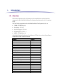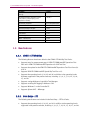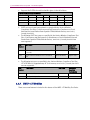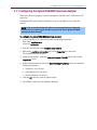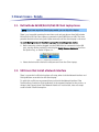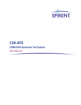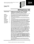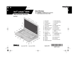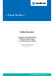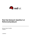
1
8100 Mobile Device Test System
Radio Access: LTE
Product Update
Spirent
541 Industrial Way West
Eatontown, NJ 07724 USA
Email: [email protected]
Web: http://www.spirent.com
AMERICAS 1-800-SPIRENT • +1-818-676-2683 • [email protected]
EUROPE AND THE MIDDLE EAST +44 (0) 1293 767979 • [email protected]
ASIA AND THE PACIFIC +86-10-8518-2539 • [email protected]
Page Part Number: 71-006692, Version A0
Copyright © 2012 Spirent. All Rights Reserved.
All of the company names and/or brand names and/or product names referred to in this document, in particular, the
name “Spirent” and its logo device, are either registered trademarks or trademarks of Spirent plc and its
subsidiaries, pending registration in accordance with relevant national laws. All other registered trademarks or
trademarks are the property of their respective owners.
The information contained in this document is subject to change without notice and does not represent a
commitment on the part of Spirent. The information in this document is believed to be accurate and reliable;
however, Spirent assumes no responsibility or liability for any errors or inaccuracies that may appear in the
document.
Table of Contents
1. Introduction .......................................................................................... 1
1.1.
Overview ........................................................................................... 1
1.2.
New Features ..................................................................................... 2
1.2.1. CDMA - LTE Mobility ........................................................................... 2
1.2.2. Data Retry - LTE ................................................................................. 2
1.2.3. Data Throughput - LTE ....................................................................... 3
1.2.4. RF Performance - LTE ......................................................................... 3
1.2.5. UMTS - LTE Mobility ........................................................................... 4
1.3.
Maintenance Updates ........................................................................ 5
1.3.1. CDMA - LTE Mobility ........................................................................... 5
1.3.2. Data Retry - LTE ................................................................................. 5
1.3.3. Data Throughput - LTE ....................................................................... 5
1.3.4. RF Performance - LTE ......................................................................... 5
1.3.5. UMTS - LTE Mobility ........................................................................... 6
1.4.
Known Issues .................................................................................... 6
1.4.1. CDMA - LTE Mobility ........................................................................... 6
1.4.2. Data Retry - LTE ................................................................................. 7
1.4.3. Data Throughput - LTE ....................................................................... 7
1.4.4. RF Performance - LTE ......................................................................... 7
1.4.5. UMTS - LTE Mobility ........................................................................... 7
2. System Upgrade Instructions ................................................................ 9
2.1.
Overview ........................................................................................... 9
2.2.
Downloading/Unzipping the Software Update..................................... 9
2.3.
Using the Global Installer Application ............................................... 11
2.4.
Upgrading the Controller PC ............................................................. 13
2.4.1. Preparing For The Update .................................................................13
2.4.2. Updating Intrig Data Monitor ...........................................................13
2.4.3. Updating Components - Global Installer .......................................... 14
2.4.4. Installing Logging Framework ......................................................... 14
2.4.5. Completing Test Manager Configuration.......................................... 16
2.4.6. Completing eAirAccess Configuration .............................................. 19
ii | 8100 Mobile Device Test System – LTE: Product Update
2.4.7. Completing AirAccess C2K Installation ............................................. 19
2.4.8. Correct Calibration Files Access Permissions - Windows 7 ................ 21
2.5.
Upgrading the Client Laptop ............................................................. 24
2.5.1. Updating Spirent AT Control ............................................................ 24
2.5.2. Updating Spirent Data Client ........................................................... 24
2.6.
Upgrading the Application Server ..................................................... 25
2.6.1. Updating Spirent Data Client ........................................................... 25
2.6.2. Updating Xlight IPv6 FTP Server Configuration ................................ 25
2.7.
Updating the EPC Server................................................................... 27
2.8.
Updating the E2010S ....................................................................... 29
2.8.1. Installing Logging Framework ......................................................... 29
2.8.2. Installing Layer 3 Components ........................................................ 29
2.8.3. Installing E2010 Manager ............................................................... 30
2.8.4. Installing E2010 Core Software ....................................................... 30
2.9.
Updating the Router\Switch Configurations ...................................... 45
2.9.1. Updating the Cisco 1811 Router ....................................................... 45
2.9.2. Updating the Cisco 2600 Router ...................................................... 48
2.9.3. Updating the Dell 6248 Switch ........................................................ 50
2.10. Installing the Agilent ESG Waveform Files ......................................... 53
2.10.1. Overview ....................................................................................... 53
2.10.2. Setting Up the LAN Interface Configuration for the ESG .................. 53
2.10.3. Downloading Waveform Files to the ESG ........................................ 54
2.11. Configuring the Agilent EXA/MXA Spectrum Analyzer ........................ 55
2.12. Installing New System Cables ........................................................... 56
2.12.1. Ethernet Cable ............................................................................... 56
2.12.2. Synchronization Cable ................................................................... 56
8100 Mobile Device Test System – LTE: Product Update | iii
3. Known Issues - Details ........................................................................ 57
3.1.
Dell Latitude E6500/E6510/E6520 Client Laptop Issue ..................... 57
3.2.
UE Drivers that Install a Network Interface......................................... 57
3.3.
3.4.
Unable to Abort Calibration .............................................................. 58
Disabling Microsoft Update .............................................................. 59
3.4.1. Windows XP and Windows Server 2003 ........................................... 59
3.4.2. Windows 7 ...................................................................................... 60
3.4.3. Windows Server 2008 ..................................................................... 61
3.5.
Creating a New Platform File ............................................................. 62
3.6.
Disabling Internet Protocol on the UE Network Connection ................ 63
1.
Introduction
1.1. Overview
This Product Update contains information on the modifications of the Test Packs
supported on the 8100 Mobile Device Test System from the version 4.3.1 to version
4.4.0.
The Test Packs supported on the 8100 Mobile Device Test System v4.4.0 are:
•
CDMA - LTE Mobility v1.3
•
Data Retry - LTE v1.3
•
Data Throughput - LTE v1.4
•
RF Performance - LTE v1.5
•
UMTS - LTE Mobility v1.0
8100 Mobile Device Test System - Radio Access: LTE v4.4.0 consists of the software
components listed in the table below.
Software
Version
8100-B Series Platform
1.1.67
8100-B 100 Platform
1.5.350
Platform Setup Guides
1.0.2
AirAccess C2K
4.30.009
AirAccess WCDMA HS
4.42.104
AT4 Log Generator COM Interface
1.6.0.12
AT4 Logging Framework Runtime
1.6.1.4
CDMA 8960 Driver
3.3.0.17
CDMA - LTE Mobility
1.3.68
CS8 Development Library
1.1.17
Custom Report Engine
1.1.17
Data Retry - LTE
1.3.155
Data Throughput - LTE
1.4.234
Development Library Services
1.50.143
E2010S Driver V1
2.8.0008
E2010S Driver V2
2.8.0008
eAirAccess
1.40.030
Intrig Data monitor
1.2.9
RF Performance - LTE
1.5.370
2 | 8100 Mobile Device Test System – LTE: Product Update
Software
Version
Spirent AT Control (installed on Client
Laptop)
1.5.25
Spirent Data Client (installed on the
Controller PC, Client Laptop, and
Application Server)
1.12.213
Spirent EPC Software
10.0.0.48.paw.19.tsu
Spirent WCE-IAPI
3.51.034
Spreadsheet Report Engine
1.5.67
SR5500 TestKit
3.51.002
TCU2 Driver
1.0.16
Test Manager
2.5.319
UMTS - LTE Mobility
1.0.6.1
Universal DM V2
4.7.1
1.2. New Features
1.2.1. CDMA - LTE Mobility
The following features have been added to the CDMA - LTE Mobility Test Packs:
•
Supports tests for measurement gaps in VZW LTE-CDMA InterRAT Operations Test
Plan and in VZW LTE-CDMA InterRAT Operations for SVD Test Plan.
•
Supports the update for the VZW LTE-CDMA InterRAT Operations Test Plan from v5.0
to v6.0.
•
Supports VZW LTE-CDMA InterRAT Operability Test Plan v1.5.
•
Supports the operating bands 3, 24, 25 and 26 in addition to the operating bands
that were supported in the previous release, including: 1, 2, 4, 5, 7, 10, 12, 13, 14,
17, and 20.
•
Supports saving eAirAccess logs within Test Manager.
•
Supports enabling RLP logging in AirAccess C2K.
•
Supports Windows 7 on the Controller PC.
•
Supports Spirent UICC – Milenage.
1.2.2. Data Retry - LTE
The following new features are included in the Data Retry – LTE Test Packs:
•
Supports the operating bands 3, 24, 25, and 26 in addition to the operating bands
supported in the previous release, including: 1, 2, 4, 5, 7, 10, 12, 13, 14, 17, and 20.
8100 Mobile Device Test System – LTE: Product Update | 3
•
Supports VZW Compliance Test Plan LTE Data Retry Version 9.0.
•
Supports saving eAA logs from within Test Manager.
•
Supports Windows 7 on the Controller PC.
1.2.3. Data Throughput - LTE
The following new features are included in this release of the Data Throughput - LTE Test
Packs:
•
Supports the CQI/ACK/NACK Stats collection and CQI/ACK/NACK charts in Test
Manager.
•
Supports L1/L2 logging collection.
•
Support for Physical Layer throughput calculation/Physical Layer throughput chart.
•
Supports RLC Stats collection/RLC Stats chart in Test Manager.
•
Supports CQI, CFI, and UE Specified Aggregation Level as test case parameters.
•
Support for real time throughput summary pane in Test Manager.
•
Support for the MTU parameter in UE file.
•
Supports clearing/saving the eAA OTA database.
•
Supports collection of UE category information in Test Manager.
•
Support for time-based FTP (optimized FTP) instead of file-based.
•
Supports the Spirent UICC card.
•
Supports Windows 7 on the Controller PC.
•
Supports the operating bands 3, 24, 25, and 26 in addition to the operating bands
supported in the previous release; including: 1, 2, 4, 5, 7, 10, 12, 13, 14, 17, and 20.
1.2.4. RF Performance - LTE
The following new features are included in this release of the RF Performance - LTE Test
Packs (refer to the user manual for details):
•
Optimizations have been implemented to reduce test time execution by 40%. Test
Manager includes built-in intelligence to combine and execute similar tests without
tearing down the LTE attach between tests.
•
Supports the additional E-UTRA operating bands given in the table below.
E-UTRA
Operating
Band
Uplink (UL) operating band
BS receive
UE transmit
Downlink (DL) operating band
BS transmit
UE receive
Duplex
Mode
FUL_low – FUL_high
FDL_low – FDL_high
24
1626.5 MHz – 1660.5 MHz
1525 MHz – 1559 MHz
FDD
25
1850 MHz – 1915 MHz
1930 MHz – 1995 MHz
FDD
26
814 MHz – 849 MHz
859 MHz – 894MHz
FDD
4 | 8100 Mobile Device Test System – LTE: Product Update
•
Supports the E-UTRA channel bandwidths given in the table below.
E-UTRA Band/Channel Bandwidth
E-UTRA Band
1.4 MHz
3 MHz
5 MHz
10 MHz
15 MHz
20 MHz
24
Yes
Yes
Yes
Yes
Yes
Yes
25
Yes
Yes
Yes
Yes
Yes
Yes
26
Yes
Yes
Yes
Yes
Yes
Yes
•
SVLTE test cases have been updated to comply with the Verizon Wireless
Compliance Test Plan: Conformance and Performance for Simultaneous Circuit
Switched Voice and Packet Data Capable LTE Multi-Mode Devices, version 4.0,
issued: June 2011.
•
The following SVLTE test cases as specified in the Verizon Wireless Compliance Test
Plan: Conformance and Performance for Simultaneous Circuit Switched Voice and
Packet Data Capable LTE Multi-Mode Devices, version 4.0, issued: June 2011 are
now supported.
Test
Number
Test Name
2.1
LTE Performance in the Presence of a 1xRTT
Voice Call
2.1.2
LTE RF Output Power Back-off Conformance
Test
•
Test Pack
Additional
Required
Instruments
TP-RF-SVLTE-TP1
Agilent 8960
The following test cases as specified in the Verizon Wireless Compliance Test Plan,
LTE 3GPP Band 13 Supplementary RF Conformance, version 10.0, issued: June 2011
are now supported.
Test
Number
Test Name
2
Transmitter Tests
2.8
Configured Output Power
Test Pack
Additional
Required
Instruments
TP1
1.2.5. UMTS - LTE Mobility
There are no new features included in this release of the UMTS - LTE Mobility Test Packs.
8100 Mobile Device Test System – LTE: Product Update | 5
1.3. Maintenance Updates
1.3.1. CDMA - LTE Mobility
The following maintenance updates have been added to the CDMA - LTE Mobility Test
Packs:
•
Supports continuing to run full test case if intermediate step fails.
•
Supports not verifying data continuity.
•
Supports delay while switching RAN emulators.
•
Supports provisioning APN in a test case parameter.
1.3.2. Data Retry - LTE
The following maintenance updates have been added to the Data Retry - LTE Test Packs:
•
Supports UE automatic attach to internet PDN.
•
Supports enhanced parameters for multi-PDN settings.
1.3.3. Data Throughput - LTE
The following maintenance updates have been added to the Data Throughput - LTE Test
Packs:
•
Test Manager Event window results enhancement.
•
Benchmark Report enhancement.
•
Detail Report enhancement.
•
Advanced Channel Models enhancement.
1.3.4. RF Performance - LTE
The following maintenance updates have been added to the RF Performance - LTE Test
Packs:
•
Failures seen with "VZW Supplementary RF Conformance 2.4 Spurious Emissions
Band UE Coexistence" and "VZW Supplementary RF Conformance 2.9 Spurious
Emissions Band UE Coexistence" have been addressed with this release of LTE RF by
introducing an external filter between the spectrum analyzer and the SR8068 TCU.
These external filters will be automatically shipped to the existing customers.
•
The occasional throughput failures seen with Receiver Sensitivity and Receiver
Blocking tests due to incorrect calculation of “FER” due to a timing issue have been
addressed.
6 | 8100 Mobile Device Test System – LTE: Product Update
1.3.5. UMTS - LTE Mobility
No maintenance updates have been added to the UMTS - LTE Mobility Test Packs.
1.4. Known Issues
The following issues are applicable to all Test Packs on the 8100 Mobile Device Test
System v4.4.0:
•
There is an issue with removing the test data cards and test phones from Dell
Latitude E6500/E6510/E6520 Client Laptops connected through the PCMCIA slot or
USB. If the client laptop model is a Dell Latitude E6500/E6510. Refer to Section 3.1
for details.
•
There is a potential conflict that can occur if the device installs a Network Interface
driver. Refer to Section 3.2 for details.
•
Attempting to abort calibration causes Test Manager to freeze. Refer to Section 3.3
for details.
•
The log file format of the OTA messages has changed; therefore OTA messages
collected with v4.3.1 cannot be decoded for viewing.
•
Installation of Microsoft Security Essentials enables Microsoft Update. Microsoft
Update must be disabled. This applies to the Controller PC, Client Laptop, and the
Applications Server. Refer to Section 0 for details.
•
Errors may be encountered if you do not update every module. If this is occurs,
uninstall and then reinstall all of the modules.
•
Platform Files created using previous releases are not automatically upgraded
correctly in this release. Delete all previously created Platform Files and generate
new Platform Files prior to executing any test cases. Refer to Section 0 for details.
•
Bandwidths 1.4M, 3M, 15M and 20MHz are enabled, but have not been fully tested
due to UE availability.
•
Band classes 1, 2, 3, 5, 7, 10, 12, 14, 20, 24, 25, 26, and 27 are enabled, but have
not been fully tested due to UE availability.
1.4.1. CDMA - LTE Mobility
The following issues are applicable to the CDMA - LTE Mobility Test Packs:
•
The SIB 8 field specifying the CDMA time is not populated correctly. UEs that rely on
this field to perform measurements of the CDMA systems during scheduled LTE
measurement gaps may not perform correctly during tests requiring this capability.
•
In the IOT test cases that test the LTE/eHRPD handover by using FTP to perform
transfer verification; if the UE takes more than one minute to finish the handover, the
existing FTP transfer is terminated. A new FTP transfer is then used to verify FTP
transmission after the handover.
8100 Mobile Device Test System – LTE: Product Update | 7
1.4.2. Data Retry - LTE
There are no known issues specifically applicable to the Data Retry - LTE Test Packs.
1.4.3. Data Throughput - LTE
The following issues are applicable to version 1.40 the Data Throughput LTE Test Packs:
•
For FTP over IPv6 at maximum throughput rates greater than 25Mbps, you must use a
client laptop running Windows 7 and an Application Server running Windows Server
2008.
•
The Advanced Channel Model test requires the E2010 to be calibrated for 1dB
tolerance limits. Call Spirent Customer Service for details.
•
A test may encounter a radio link failure when the IMS PDN is enabled and the UE
refreshes its subscription by sending another SUBSCRIBE. This typically happens
when the test involves an FTP/UDP transfer for more than 40 minutes after attach.
•
Performance degradation may be seen for high throughput test cases when RLC Stats
or L1/L2 logging is enabled. We recommend that you disable RLC and L1/L2 logging
only if modulation is 64QAM, MIMO is enabled, and the TB Size is 25456 or above.
•
If the COM port of the UE is locked, unplug and reconnect the UE.
•
CQI information in the CQI Chart and in the detail/benchmark report is not logged for
the Transmission Mode 4 and Transmission Mode 6 Test Cases.
•
In certain RF configurations, the calculated MAC/Physical Layer Throughput may be
slightly off and should only be used as a reference.
•
When a system is cabled with SR5500M, we recommend that you use the Dedicated
Mode to achieve maximum RSTP range across all band classes.
1.4.4. RF Performance - LTE
The following issues are applicable to the RF Performance – LTE Test Packs:
•
Microsoft Windows 7 is not supported on the Controller PC.
•
LTE RF test cases will not run properly if the UE is permitted to acquire an IP address
when it is connected to the Controller PC for UE automation. In this case, the internet
protocol feature of the UE network interface must be disabled. Refer to Section 3.6
for details.
1.4.5. UMTS - LTE Mobility
The following issues are applicable to the UMTS – LTE Mobility Test Packs:
•
IOT was performed with the only device available (Sierra Wireless U313 data card).
Interoperability with other devices is not known.
8 | 8100 Mobile Device Test System – LTE: Product Update
•
A new component from the Global Installer DVD (UE AT Interface for CS8) must be
installed when upgrading the UMTS - LTE Mobility module to this release. You can
select this component for installation under the Instruments tab, as shown in Figure
1-1.
Figure 1-1: Global Installer – Instruments Tab
•
Note that the Global Installer software may not correctly detect that the UE AT
Interface for CS8 SW is installed. This is due to a naming convention mismatch.
If you encounter this issue, use the Windows Control Panel to confirm that the correct
software applications are installed.
2. System Upgrade Instructions
2.1. Overview
The following sections contain the steps necessary to install the LTE Test Packs and the
necessary supporting software components on an existing system.
NOTE: The instructions in this document are written specifically for upgrading the
configuration from version 4.3.1 to version 4.4.0 only.
If starting from any other version, you must first update the system to version 4.3.1
by referring to the appropriate product updates.
After the version 4.3.1 update is complete, continue with the upgrade instructions
in this document.
These steps include:
•
Downloading and unzipping the Software Update Package from the Customer
Support website.
•
Using the Global Installer application.
•
Updating the Controller PC.
•
Updating the Client Laptop.
•
Updating the Application Server.
•
Updating the EPC Server.
•
Updating the E2010S.
•
Updating the Cisco 1811/2600 Router Configuration.
•
Updating the Dell 6248 Switch Configuration.
•
Updating the Agilent ESG.
•
Updating the Agilent EXA/MXA Spectrum Analyzer.
•
Installing new System Cables.
2.2. Downloading/Unzipping the Software Update
To download/unzip the software update:
1. Log in to the Spirent Customer Service Center website at http://support.spirent.com
using the e-mail address and password assigned to you by Spirent.
2. Select Download Software Updates>Wireless>8100 Radio Access – LTE Testing
(Version 4.4.0)>Download to download the latest release.
3. Locate the downloaded file in Windows Explorer.
10 | 8100 Mobile Device Test System – LTE: Product Update
4. Right-click the file and select Extract All from the menu, as shown in Figure 2-1.
Figure 2-1: Extract All Files
5. Use the Extraction Wizard to extract the files to a known location, as shown in Figure
2-2.
NOTE: We recommend that you extract the zipped package files to a portable USB
device. These files are needed to update multiple computers on the system.
The location of these files will be referred to as <8100 – LTE 4.4.0 Installer Root>
throughout the remainder of this document.
Figure 2-2: Using the Extraction Wizard
8100 Mobile Device Test System – LTE: Product Update | 11
2.3. Using the Global Installer Application
This section provides information on how to use the Global Installer. This application
allows you to update different computers in the system using a convenient userinterface.
To run the Global Installer application:
1. Navigate to the <8100 – LTE 4.4.0 Installer Root> folder.
2. Run the setup.exe file.
The 8100 Mobile Device Test System Installer window displays, as shown in Figure
2-3.
NOTE: The version numbers shown in following Global Installer figures may not
reflect the current software version numbers.
For the correct version numbers, refer to the table on page 1.
Figure 2-3: 8100 Mobile Device Test System Installer Window
The Global Installer application organizes the software components into separate tabs,
shown in Figure 2-3. The icon next to each component indicates which components have
been detected as installed on the system.
12 | 8100 Mobile Device Test System – LTE: Product Update
The following list describes the different icons used in the Global Installer:
The software is not installed.
A different version of the software is already installed.
The software is selected for install (also displays on the Install List).
The correct version of the software is already installed.
To install software components using the Global Installer application:
1. To mark a software component for installation, select the component.
The icon changes to a green checkmark and the component is added to the Install
List.
2. Add additional components as necessary.
You can add components from different tabs prior to starting the installation.
NOTE: In some cases, the order of installation is important. Follow the instructions
in the sections below regarding installation order.
3. Click the Installation toolbar button
to begin the installation. The progress of the
install displays on the left pane. When complete, a Summary window displays.
8100 Mobile Device Test System – LTE: Product Update | 13
2.4. Upgrading the Controller PC
Connect the device containing the unzipped installer to the Controller PC.
2.4.1. Preparing For The Update
1. Ensure that the following applications are not running:
a. Test Stand Sequence Editor
b. eAirAccess
c. AirAccess C2K
d. AirAccess WCDMA-HS
e. Intrig IDM
f.
Universal DM V2
g.
Spirent Data Client
2. Save the existing security passwords.
a. Start Test Manager and select Help>About>Passwords.
b. Click the Export button and use the file browser to export the passwords to
passwords.csv.
c. Close Test Manager.
2.4.2. Updating Intrig Data Monitor
1. Uninstall any previous versions of IDM by selecting Start> Add or Remove Programs.
2. Navigate to the <8100 – LTE 4.4.0 Installer Root>\eAirAccess\Controller PC\IDM
folder.
3. Execute idm-x.x.x.exe and accept the defaults.
4. Modify the registry entries after IDM is installed:
a. Select Start>Run. Type regedit and press Enter.
Windows 7 Users: Type regedit in the Search field and press Enter.
b. If the User Account Control window displays, click Yes to proceed.
c. Expand HKEY_LOCAL_MACHINE\SOFTWARE\Intrig. Right-click the IDM folder
and select Permissions.
d. Select the Users account and under Permissions, select Allow for the Full Control
option, as shown in Figure 2-4.
Click Apply and then OK.
14 | 8100 Mobile Device Test System – LTE: Product Update
Figure 2-4: IDM Permissions Window
2.4.3. Updating Components - Global Installer
For details on how to use the Global Installer application, refer to Section 2.3.
To update components in the Global Installer:
1. If the correct version of Test Manager is not installed, select the Test Manager
component.
2. Click the Installation toolbar button to begin the installation.
3. Navigate through all the tabs from left to right and select any components that are
indicated to be out of date or missing.
NOTE: There are now two versions of the E2010S Driver. Select both for installation.
4. Click the Installation toolbar button
to begin all installations.
5. Restart the Controller PC.
2.4.4. Installing Logging Framework
1. Uninstall any previous versions of Logging Framework components.
a. Stop the Logging Framework by selecting Start>All Programs>AT4
Wireless>Logging Framework Runtime>Stop Logging Framework.
b. An Information window displays verifying that Logging Framework has been
stopped, as shown in Figure 2-5.
8100 Mobile Device Test System – LTE: Product Update | 15
Figure 2-5: Logging Framework Information Window
c. From the Control Panel, select Add or Remove Programs and remove the
following components:
i.
AT4 Wireless Logging Generator COM Interface
ii. AT4 Wireless Dissectors
d. Uninstall LogAgent by selecting Start>All Programs>AT4 Wireless>Logging
Agent>Uninstall.
2. Install the Logging Framework:
a. Navigate to the <8100 – LTE 4.4.0 Installer Root>\eAirAccess\Controller
PC\Logging Framework folder.
b. Execute Logging Framework Runtime Setup.exe and accept the defaults.
c. Execute AT4 Wireless Dissectors Setup.exe file and accept the defaults.
16 | 8100 Mobile Device Test System – LTE: Product Update
2.4.5. Completing Test Manager Configuration
2.4.5.1
Configuring Test Manager to Run as Administrator - Windows 7
NOTE: Perform these instructions only if your system includes a Windows 7
Controller PC.
1. Start the Windows 7 Task Scheduler (enter task) in the Run Application window, as
shown in Figure 2-6.
Figure 2-6: Starting Task Scheduler
2. Select the Import Task option from Actions panel, as shown in Figure 2-7.
Figure 2-7: Task Scheduler Window
8100 Mobile Device Test System – LTE: Product Update | 17
3. Navigate to the <8100 – LTE 4.4.0 Installer Root>\Test Manager\PUG Script Files\
folder, select the tmtask.xml file and click Open, as shown in Figure 2-8.
Figure 2-8: Opening the .xml File
4. A New Task window displays with the required parameters already populated. Click
OK and close the Task Scheduler.
5. Replace the existing Test Manager Desktop Shortcut by navigating to the <8100 – LTE
4.4.0 Installer Root>\Test Manager\PUG Script Files folder, as shown in Figure 2-9.
Figure 2-9: PUG Script Files
6. Copy the Test Manager shortcut and move it to the Desktop.
A Copy File window displays, as shown in Figure 2-10. Select Copy and Replace.
18 | 8100 Mobile Device Test System – LTE: Product Update
Figure 2-10: Copy and Replace Confirmation Window
7. The Test Manger application will now run with the highest administrative privileges
when this icon is selected.
2.4.5.2
Updating Test Manager Passwords and User Files
1. Start Test Manager and select Help>About>Passwords.
2. Select and open the passwords.csv file exported in Section 2.4.1 on page 13.
NOTE: Contact your local Spirent Sales Manager if new or additional passwords are
required for the updated features.
3. Delete all older platform files.
In Test Manager, select File>Open>Platform File.
4. Create a new platform file.
In Test Manager, select File>New>Platform File. Refer to Section 0 for details on
creating Platform Files.
5. Update all UE Files from previous versions.
In Test Manager, select File>Open>UE File and save the old UE Files again.
6. Update all Session Files from previous versions.
In Test Manager, select File>Open>Session File and save the old Session Files again.
7. Run a System Calibration for the B-Series platform and/or the B-100 platform.
8. Close Test Manager.
8100 Mobile Device Test System – LTE: Product Update | 19
2.4.6. Completing eAirAccess Configuration
1. Launch eAirAccess by double-clicking the desktop icon.
2. Select Help>Enter Password.
The Password window displays, as shown in Figure 2-11.
3. Enter the appropriate password and click OK.
Figure 2-11: Entering the eAirAccess Password
4. Close eAirAccess.
2.4.7. Completing AirAccess C2K Installation
NOTE: Follow these instructions only if C2K instruments are included in your
system.
1. Launch AirAccess C2K by double-clicking the desktop icon.
2. Select Help>Enter Application Password. The Application Password window
displays, as shown in Figure 2-12.
3. Enter the appropriate password and click OK.
20 | 8100 Mobile Device Test System – LTE: Product Update
Figure 2-12: Entering the AirAccess C2K Password
4. Select File>Install Instrument Firmware.
5. The SR3452, SR3462, and SR3600 Instrument windows display, as shown in the
following figures.
Figure 2-13: SR3452 Instrument Window
Figure 2-14: SR3462 Instrument Window
8100 Mobile Device Test System – LTE: Product Update | 21
Figure 2-15: SR3600 Instrument Window
6. Wait for the installation to complete.
A window may display prompting you to turn the instrument off and power it on
again. Follow the instructions to restart the instrument and close the window.
7. Close AirAccess C2K
2.4.8. Correct Calibration Files Access Permissions - Windows 7
NOTE: Perform these instructions only if your system includes a Windows 7
Controller PC.
1. Using Windows Explorer, navigate to the C:\ProgramData\Spirent Communications
folder as shown in Figure 2-16.
Figure 2-16: Spirent Communications Folder
2. Right-click the Development Library Services folder and select Properties from the
menu.
In the Properties window, select the Security tab.
3. Select the Users group to view the Permissions, as shown in Figure 2-17.
22 | 8100 Mobile Device Test System – LTE: Product Update
Figure 2-17: Properties Window – User Permissions
4. Click the Advanced button and select the User Permission entries corresponding to
“Read & Execute”.
5. Click the Change Permissions button, as shown in Figure 2-18.
Figure 2-18: Changing the Read & Execute Permissions
6. Under Full Control, select Allow, as shown in Figure 2-19.
8100 Mobile Device Test System – LTE: Product Update | 23
Figure 2-19: Selecting Permission Options
7. Click OK.
8. In the Advanced Security Settings window, select the Replace all child object
permissions with inheritable permission from this object option, as shown in
Figure 2-20. This option applies the change to all subfolders and files.
Figure 2-20: Advanced Security Settings Window
9. Verify that you have a new permission entry for Users that allows Full Control, as
shown in Figure 2-21.
Click Apply and OK save the settings and exit the window.
24 | 8100 Mobile Device Test System – LTE: Product Update
Figure 2-21: Verifying Permissions Setting
10. Calibration procedures can now be performed on existing and/or default files
present in the ProgramData\Spirent Communications\Development Library Services
folder.
2.5. Upgrading the Client Laptop
Connect the device containing the unzipped installer to the Client Laptop.
2.5.1. Updating Spirent AT Control
To update Spirent AT Control:
1. Select Start>Control Panel>Add/Remove Programs.
2. Uninstall the Spirent AT Control application.
3. Navigate to the <8100 – LTE 4.4.0 Installer Root>\eAirAccess\Controller PC\Spirent AT
Control folder.
4. Execute setup.exe and accept the defaults.
2.5.2. Updating Spirent Data Client
For details on how to use the Global Installer application, refer to Section 2.3 on page
11.
To update Spirent Data Client:
1. Start the Global Installer application.
2. If the correct version of Spirent Data Client is not installed, select the Spirent Data
Client component.
3. Click the Installation toolbar button
4. Restart the Client Laptop.
to begin the installation.
8100 Mobile Device Test System – LTE: Product Update | 25
2.6. Upgrading the Application Server
To update the Application Server:
1. Connect the device containing the unzipped installer to the Application Server.
2. From the Controller PC, use Remote Desktop to login to the Application Server at
192.168.0.70.
2.6.1. Updating Spirent Data Client
For details on how to use the Global Installer application, refer to Section 2.3 on page
11.
1. Start the Global Installer application.
2. If the correct version of Spirent Data Client is not installed, select the Spirent Data
Client component.
3. Click the Installation toolbar button
to begin the installation.
4. Exit the Global Installer application.
2.6.2. Updating Xlight IPv6 FTP Server Configuration
1. Double click the Xlight FTP Server icon from the desktop as shown in Figure 2-22.
Figure 2-22: Xlight IPv6 FTP Icon
2. The Duplicated Process window shown in Figure 2-23 displays. Click Yes to proceed.
Figure 2-23: Duplicated Process Warning Window
26 | 8100 Mobile Device Test System – LTE: Product Update
3. Select the fd00:0:20:1::4 IPv6 server and click the Modify Virtual Server
Configuration button, as shown in Figure 2-24.
Figure 2-24: Modify Virtual Server Configuration Button
4. Under the General tab, change the "Maximum idle time" parameter to 120 and select
the Enable the anti-idle scheme option, as shown in Figure 2-25.
Figure 2-25: Enable Anti-idle Scheme Option
5. Click OK to close all Xlight windows.
8100 Mobile Device Test System – LTE: Product Update | 27
2.7. Updating the EPC Server
NOTE: If the steps in Section 2.4.7 have been completed, you can skip this section.
1. From the Controller PC, navigate to C:\Program Files\Spirent
Communications\SR3600\x.x.x, as shown in Figure 2-26.
If there is more than one folder, open the most recent.
Figure 2-26: SR3600 Folder
2. Execute the SR3600.exe file.
3. In the Upgrade window, select Instrument>Install Firmware Update as shown in
Figure 2-27.
Figure 2-27: Opening the Firmware Update
28 | 8100 Mobile Device Test System – LTE: Product Update
4. In the Open window, navigate to
C:\Program Files\Spirent Communications\eAirAccess.
5. Select the .tsu file and click the Open button, as shown in Figure 2-28.
NOTE: The version number reflected in the filename shown in Figure 2-28 may not
reflect the current software version number.
For the correct version number, refer to the table on page 1.
Figure 2-28: Opening the .tsu File
6. Wait for the update to complete (this will take several minutes), as shown in Figure
2-29.
Figure 2-29: Update Status
7. Close the SR3600 tool.
8100 Mobile Device Test System – LTE: Product Update | 29
2.8. Updating the E2010S
Connect the device containing the unzipped installer to the E2010S.
2.8.1. Installing Logging Framework
1. Uninstall any previous versions of Logging Framework components:
a. Stop the Logging Framework by selecting Start>All Programs>AT4
Wireless>Logging Framework Runtime>Stop Logging Framework.
b. An Information window displays verifying that Logging Framework has been
stopped, as shown in Figure 2-30.
Figure 2-30: Logging Framework Information Window
c. From the Control Panel, select Add or Remove Programs and remove the AT4
Wireless Logging Generator COM Interface
d. Uninstall LogAgent by selecting Start>All Programs>AT4 Wireless>Logging
Agent>Uninstall.
2. Install Logging Framework:
a. Navigate to the <8100 – LTE 4.4.0 Installer Root>\eAirAccess\E2010 Embedded
PC\Logging Framework folder.
b. Execute Logging Framework Runtime Setup Embedded PC.exe and accept the
defaults.
2.8.2. Installing Layer 3 Components
1. Uninstall any previous versions of the Layer 3 Components:
a. Stop the Layer 3 Components by navigating to C:\Program Files\Spirent
Communications\eAirAccess\L3 and double-clicking the killeNBEmu.bat script.
b. From the Control Panel, select Add or Remove Programs and remove the L3
Component Installer
2. Install the Layer 3 Components:
a. Navigate to the <8100 – LTE 4.4.0 Installer Root>\eAirAccess\E2010 Embedded
PC\Layer 3 Components folder.
b. Execute Layer3Components and accept the default settings.
30 | 8100 Mobile Device Test System – LTE: Product Update
2.8.3. Installing E2010 Manager
1. Uninstall any previous versions of the E2010Manager:
a. Open Task Manager by right-clicking the clock on the right side of the System
Tray and selecting Task Manager from the menu.
b. Under the Processes tab, select E2010Manager.exe and click the End Process
button.
c. From the Control Panel, select Add or Remove Programs and remove
E2010Manager
2. Install E2010Manager:
a. Navigate to the <8100 – LTE 4.4.0 Installer Root>\eAirAccess\E2010 Embedded
PC\E2010Manager folder.
b. Execute the setup.exe file and accept the defaults.
c. After installing the E2010Manager, execute a hard reboot of the E2010 by
pressing the power button on the front of the E2010S.
d. When the box reboots, E2010Manager should run automatically.
Verify this by opening Task Manager and confirming the E2010Manager.exe
process is running.
e. If E2010Manager is not running, start it manually by running the .exe file found
under: C:\Program Files\Spirent Communications\E2010Manager\E2010Manager.exe.
2.8.4. Installing E2010 Core Software
2.8.4.1
Installing the E2010 License File
1. Obtain a copy of the E2010 License File for the specific E2010 being upgraded. This
file can be obtained by contacting Pat Munson and giving her the unit serial number.
2. Copy the E2010 License File to C:\AT4Wireless\ E2010S License\. If this folder
does not exist, create it.
3. Copy the License File Installer, <8100 – LTE 4.4.0 Installer
Root>\eAirAccess\E2010EmbeddedPC\LTE E2010 Core\License Installer v1.0
Release 4195.exe to C:\AT4Wireless\ E2010S License\.
4. Run the License_Installer_v1.0_Release_4195.exe file to install the license.
The AT4 Wireless Licenser window displays, as shown in Figure 2-31
8100 Mobile Device Test System – LTE: Product Update | 31
Figure 2-31: AT4 Wireless Licenser Window
5. Under the E2010 tab, select Load License File.
The Open License File window displays.
6. Navigate to C:\AT4Wireless\E2010S License\ and select the
E2010_SNBWTSxxxxxxx.xml.licx file where “xxxxxxx” is the E2010S serial number.
Click Open.
7. Run the License_Installer_v1.0_Release_4195.exe file.
2.8.4.2
Installing E2010S Software
1. Navigate to <8100 – LTE 4.4.0 Installer Root>\eAirAccess\E2010EmbeddedPC\LTE
E2010 Core\, and run the LTE_E2010_Software_Package_v2.5.1.6 setup.exe file.
2. In License Agreement window, select I accept the terms of the license agreement
and click the Next button, as shown in Figure 2-32.
32 | 8100 Mobile Device Test System – LTE: Product Update
Figure 2-32: E2010 Software License Agreement Window
3. In Choose Components window, select all components except Overwrite
calibration, as shown in Figure 2-33. Click the Install button.
Figure 2-33: Choose Components Window
4. In the Default AT4 Wireless LTE Product Selection window, select S1-AP and click OK,
as shown in Figure 2-34.
8100 Mobile Device Test System – LTE: Product Update | 33
Figure 2-34: Default AT4 Product Selection Window
5. In the SU_Manager x.x.x.x Uninstall window, click Yes.
6. In SU_Manager Uninstall Wizard Welcome window shown in Figure 2-35, click Next.
Figure 2-35: SU_Manager Uninstall Wizard – Welcome
7. In the Uninstall SU_Manager window, click Next, as shown in Figure 2-36.
34 | 8100 Mobile Device Test System – LTE: Product Update
Figure 2-36: Uninstalling SU_Manager
8. The Choose Components window displays, as shown in Figure 2-37.
Click the Uninstall button.
Figure 2-37: SU_Manager Uninstall Wizard – Choose Components
9. In the Completing the SU_Manager Uninstall Wizard window shown in Figure 2-38,
click Finish.
Figure 2-38: Completing the SU_Manager Uninstall
8100 Mobile Device Test System – LTE: Product Update | 35
10. A message displays verifying that the software was successfully removed, as shown
in Figure 2-39. Click OK.
Figure 2-39: Software Successfully Removed Message
2.8.4.3
Installing AT4 Toolbox 2.0
1. In the Installer Language window, select English and click OK.
2. In the AT4ToolboxInstaller_2.0 Setup window, click Next.
3. In the License Agreement window, click I Agree.
4. In the Choose Install Location window, click Install.
5. In the Installation Complete window, click Next.
6. In the Completing the AT4ToolboxInstaller_2_0 Setup window, click Finish.
2.8.4.4
Updating the CAL Agent
1. In the CAL_AGENT Uninstall window shown in Figure 2-40, click Yes.
Figure 2-40: CAL_AGENT Uninstall Window
2. The CAL_AGENT Uninstall Wizard Welcome window displays, as shown in Figure
2-41.
Click Next to proceed.
36 | 8100 Mobile Device Test System – LTE: Product Update
Figure 2-41: CAL_AGENT Uninstall Wizard – Welcome
3. In the Uninstall CAL_AGENT window, click Next.
Figure 2-42: CAL_AGENT Uninstall Wizard – Choose Components
4. In the Choose Components window shown in Figure 2-42, click Uninstall.
5. In the Completing the Uninstall Wizard window shown in Figure 2-43, click Finish.
8100 Mobile Device Test System – LTE: Product Update | 37
Figure 2-43: Completing the Uninstall Wizard
6. A message displays verifying that CAL_AGENT successfully removed, as shown in
Figure 2-44. Click OK.
Figure 2-44: Software Successfully Removed Message
7. In the Check Calibration Data window shown in Figure 2-45, click OK.
Figure 2-45: Check Calibration Data Window
8. In the LTE E2010 Signaling Unit Software Installer Setup window shown in Figure
2-46, click Yes.
Figure 2-46: Execute the Upgrade Procedure Window
38 | 8100 Mobile Device Test System – LTE: Product Update
9. The HW SET MC message shown in Figure 2-47 displays. Click OK.
Figure 2-47: HW SET MC Message – Turn Boards On
10. The HW SET MC window shown in Figure 2-48 displays, click OK.
Figure 2-48: HW SET MC Message – If Boards Are Off
11. A Command window displays verifying the MCH Configuration Parameters, as shown
in Figure 2-49.
8100 Mobile Device Test System – LTE: Product Update | 39
Figure 2-49: MCH Configuration Parameter Verification
12. The upgrade process will now continue for several minutes.
13. When the upgrade procedure is completed, the window shown in Figure 2-50
displays.
Verify that the FPGAs versions match those circled in Figure 2-50 and that the E2010
has been successfully upgraded. If it is a 2 Cell unit, there will also be verification
that Cell B has been successfully upgraded. Press the Space Bar to continue.
40 | 8100 Mobile Device Test System – LTE: Product Update
Figure 2-50: Check Versions Verification
14. In the Installation Complete window, click Close.
8100 Mobile Device Test System – LTE: Product Update | 41
2.8.4.5
Applying the NetBootLoader Patch
1. Double-click the PuTTY icon
on the E2010 desktop.
2. In the PuTTY Configuration window, load GPP-A, as shown in Figure 2-51.
Click Open to continue.
Figure 2-51: PuTTY Configuration Window
3. Click ApplicationLauncher on the Windows system tray, as shown in Figure 2-52.
Figure 2-52: Application Launcher Icon
4. Select Reboot SU to reboot the E2010.
5. This will take several minutes.
Monitor the PuTTY window closely. During the reboot process, the NetBootLoader
version displays on the PuTTY window for about fifteen (15) seconds, as shown in
Figure 2-53.
Make a note of the first three digits of the “Version of running NetBootLoader”. In the
example given in Figure 2-53, it is “110”.
42 | 8100 Mobile Device Test System – LTE: Product Update
Figure 2-53: PuTTY Window – NetBootLoader Version
6. Perform the following steps only if the first three digits of the NetBootLoader version
are “110”. Otherwise, skip the steps below.
a. Under the <8100 – LTE 4.4.0 Installer Root>\eAirAccess\E2010 Embedded
PC\LTE E2010 Core folder, double-click UpdateBootscript.bat to update the
E2010 boot script.
b. The Command Prompt window displays the updated content as shown in Figure
2-54.
c. Before pressing any key, scroll up and verify that the lines circled in Figure 2-54
are present. Then press any key.
d. Before pressing any key again, scroll up and verify the circled lines were added
again after the last key press message.
Figure 2-54: Command Window – Updated Boot Script Information
8100 Mobile Device Test System – LTE: Product Update | 43
2.8.4.6
Regenerating Cal Files
1. Press the front power button on the E2010S to shut down the unit.
2. Turn off the power supply switch on the rear of the unit. Wait a few seconds and turn
the power supply switch back on.
3. On the front of the E2010S, press the power button to boot up the unit.
4. Right-click the Cal Agent icon in the Window System Tray and select Generate, as
shown in Figure 2-55.
If the Cal Agent Icon is not present, select Start>All Programs>AT4 WIRELESS>CAL
AGENT>CAL AGENT.
Figure 2-55: CAL Agent Icon
5. Generating the .cal files takes about 5-10 minutes to complete.
To verify that the files have been generated, click the Cal Agent icon. The Generate
menu item should now have a check mark. If it is disabled, the process is not
complete.
6. Right-click the SU Manager icon from the System Tray and select Restart Service.
Wait until the icon stops blinking.
2.8.4.7
Verifying E2010S Firmware Version
1. Open Window Explorer and navigate to:
C:\AT4wireless\LTE_E2010\SW_LTE_SU_R1_2_5_1_6\FW\.
2. Run the GetFWVersion script by double-clicking the GetFWVersions.at4 file.
3. Verify that the firmware versions for the four FPGA match the ones shown in Figure
2-56.
44 | 8100 Mobile Device Test System – LTE: Product Update
Figure 2-56: FPGA Firmware Versions
4. Close the window.
2.8.4.8
Edit UdpServerLoggingConfig.xml
1. Under My Computer, navigate to: U:\VOB_SW\LTE_SW_SU\WinAgents\UdpServer,
as shown in Figure 2-57.
Figure 2-57: UdpServer Folder
2. Right-click the UdpServerLoggingConfig.xml file and select Edit with Notepad ++
from the menu.
3. In the Notepad window, under the line marked <pcIpAddress>, enter 192.168.0.35
for the IP address, as shown in Figure 2-58.
8100 Mobile Device Test System – LTE: Product Update | 45
Figure 2-58: Notepad – Editing the IP Address
4. Save the document by selecting File>Save.
5. Close Notepad and Windows Explorer.
2.9. Updating the Router\Switch Configurations
To update the router/switch configurations, you need to upload the configuration file
and restart the device. The configuration files specified are found under the <8100 – LTE
4.4.0 Installer Root>\Router,Switch Config Files folder.
2.9.1. Updating the Cisco 1811 Router
Follow these instructions if your system includes a Cisco 1811 router.
1. Connect the blue RJ-45 to DB-9 cable between the CONSOLE port on the rear of the
router and the COM1 serial port on a PC. This blue cable should be included in the
box with the router.
2. Using the HyperTerminal application (or equivalent communication program),
connect to the router on COM1 using 9600 bps, 8 data bits, no parity, and 1 stop bit.
3. Start the HyperTerminal application by selecting Start>All
Programs>Accessories>Communications>HyperTerminal.
4. In the Connection Description window, enter Cisco in the Name field and click OK.
5. In the Connect To window, select COM1 in the Connect using field and click OK.
6. Under Port Settings, select the values for each setting as shown in Figure 2-59.
46 | 8100 Mobile Device Test System – LTE: Product Update
Figure 2-59: HyperTerminal COM Port Settings
7. Power on the router. Wait until the router has finished initializing.
8. HyperTerminal should display the following information:
cisco 1811XM (MPC860P) processor (revision 0x400) with 124928K/6144K bytes of
memory.
Processor board ID JMX0845L1FA (879732514)
M860 processor: part number 5, mask 2
Bridging software.
X.25 software, Version 3.0.0.
FastEthernet/IEEE 802.3 interface(s)
32K bytes of non-volatile configuration memory.
32768K bytes of processor board System flash (Read/Write)
Press RETURN to get started
9. Press Enter.
HyperTerminal displays the following prompt:
Spirent-router>
Note that the prompt displayed may look different based on the installed firmware.
10. Type “enable” and press Enter.
11. The Router now prompts you to enter a password. Type “Spirent_enable”.
12. The prompt now displays the following:
Spirent-router#
13. Press Enter.
14. Enter the following command:
copy xmodem: nvram:startup-config
15. HyperTerminal now displays:
Destination filename [startup-config]?
8100 Mobile Device Test System – LTE: Product Update | 47
16. Press Enter.
HyperTerminal now displays:
Begin the Xmodem or Xmodem-1K transfer now…
17. Use HyperTerminal to transfer the supplied configuration file by selecting
Transfer>Send File, as shown in Figure 2-60.
Figure 2-60: Send File Menu Command
18. In the Send File window, click the Browse button and select the <8100 – LTE 4.4.0
Installer Root>\Router,Switch Config Files\Cisco1811.txt configuration file.
Figure 2-61: Selecting a File
19. Click Send and wait for the transfer to complete.
20. HyperTerminal should now display text similar to the following:
6784 bytes copied in 56.084 secs (121 bytes/sec)
Spirent-router#
21. Restart the Cisco Router. Enter the following command:
reload
22. HyperTerminal now displays:
Proceed with reload? [confirm]
23. Press the “y” button.
48 | 8100 Mobile Device Test System – LTE: Product Update
24. The router restarts.
25. Press Enter and verify the prompt displays the configuration file part number with
the correct revision: 64_002863_vXX.
26. The upgrade is now complete.
2.9.2. Updating the Cisco 2600 Router
Follow these instructions if your system includes a Cisco 2600 router.
1. Connect the blue RJ-45 to DB-9 cable between the CONSOLE port on the rear of the
router and the COM1 serial port on a PC. This blue cable should be included in the
box with the router.
2. Using the HyperTerminal application (or equivalent communication program),
connect to the router on COM1 using 9600 bps, 8 data bits, no parity, and 1 stop bit.
3. Start the HyperTerminal application by selecting Start>All
Programs>Accessories>Communications>HyperTerminal.
4. In the Connection Description window, enter Cisco in the Name field and click OK.
5. In the Connect To window, select COM1 in the Connect using field and click OK.
6. Under Port Settings, select the values for each setting as shown in Figure 2-62.
Figure 2-62: HyperTerminal COM Port Settings
7. Power on the router. Wait until the router has finished initializing.
8100 Mobile Device Test System – LTE: Product Update | 49
8. HyperTerminal should display the following information:
cisco 2610XM (MPC860P) processor (revision 0x400) with 124928K/6144K bytes of
memory.
Processor board ID JMX0845L1FA (879732514)
M860 processor: part number 5, mask 2
Bridging software.
X.25 software, Version 3.0.0.
17 FastEthernet/IEEE 802.3 interface(s)
32K bytes of non-volatile configuration memory.
32768K bytes of processor board System flash (Read/Write)
Press RETURN to get started
9. Press Enter. HyperTerminal displays the following:
Spirent-router>
Note that the prompt may look different based on the installed firmware.
10. Type “enable” and press Enter.
11. The Router now prompts you for a password. Enter “Spirent_enable”.
12. Your prompt should now look like this:
Spirent-router#
13. Enter the following command:
copy xmodem: nvram:startup-config
14. HyperTerminal now displays:
Destination filename [startup-config]?
15. Press Enter. HyperTerminal now displays:
Begin the Xmodem or Xmodem-1K transfer now...
16. Use HyperTerminal to transfer the supplied configuration file by selecting
Transfer>Send File, as shown in Figure 2-63.
Figure 2-63: Send File Menu Command
50 | 8100 Mobile Device Test System – LTE: Product Update
17. In the Send File window, click the Browse button and select the <8100 – LTE 4.4.0
Installer Root>\Router,Switch Config Files\Cisco2600.txt configuration file.
Figure 2-64: Selecting a File
18. Click Send and wait for the transfer to complete.
19. Once the transfer is complete HyperTerminal should display text similar to the
following:
6784 bytes copied in 56.084 secs (121 bytes/sec)
Spirent-router#
20. Restart the Cisco Router and enter the following command:
reload
21. HyperTerminal now displays:
Proceed with reload? [confirm]
22. Press “y”.
23. The router restarts.
24. Press Enter and verify the prompt displays the configuration file part number with
the correct revision: 64_005413_vXX.
25. The upgrade is now complete.
2.9.3. Updating the Dell 6248 Switch
1. Connect the serial cable between the 9600,N,8,1 port on the rear of the switch and
the COM1 serial port on a PC. This is a standard 9 pin serial cable is included in the
box with the switch.
2. Using the HyperTerminal application (or equivalent communication program),
connect to the router on COM1 using 9600 bps, 8 data bits, no parity, and 1 stop bit.
3. Start the HyperTerminal application by selecting Start>All
Programs>Accessories>Communications>HyperTerminal.
4. In the Connection Description window, enter Dell in the Name field and click OK.
5. In the Connect To window, select COM1 in the Connect using field and click OK.
8100 Mobile Device Test System – LTE: Product Update | 51
6. Under Port Settings, select the values for each setting as shown in Figure 2-65.
Figure 2-65: HyperTerminal COM Port Settings
7. Plug in the switch. Wait until the switch has finished initializing.
8. HyperTerminal displays the following information:
(Unit 1 - Waiting to select management unit)>
Applying configuration, please wait ..........
64-005XXX_vXX>
9. Type “enable” and press Enter.
10. Your prompt should now display:
64-005XXX_vXX#
11. Enter the following command:
copy xmodem nvram startup-config
12. HyperTerminal now displays:
Mode……………………………XMODEM
Data Type………………………Config Script
Destination Filename……………startup-config
Management access will be blocked for the duration of the transfer
Are you sure you want to start? (y/n)
13. Press “y”.
14. HyperTerminal displays the following:
Ready to RECEIVE File TempConfigScript.scr in binary mode
Send several Control-X characters to cancel before transfer starts.
CKCK
15. Use HyperTerminal to transfer the supplied configuration file by selecting
Transfer>Send File, as shown in Figure 2-66.
52 | 8100 Mobile Device Test System – LTE: Product Update
Figure 2-66: Send File Menu Command
16. In the Send File window, click the Browse button and select the <8100 – LTE 4.4.0
Installer Root>\Router,Switch Config Files\Dell6248.txt configuration file.
Figure 2-67: Selecting a File
17. Click Send and wait for the transfer to complete.
18. Once the transfer is complete HyperTerminal should display text similar to the
following:
Configuration script validated.
Storing “startup-config” to non-volatile storage.
This operation may take a few minutes.
Management interfaces will not be available during this time.
19. Restart the Dell Switch:
Enter the following command:
Reload
20. HyperTerminal displays:
Management switch has unsaved changes.
Are you sure you want to continue? (y/n)
21. Press “y”.
8100 Mobile Device Test System – LTE: Product Update | 53
22. HyperTerminal displays the following:
Configuration Not Saved!
Are you sure you want to reload the stack? (y/n)
23. Press “y”.
24. HyperTerminal displays:
Reloading all switches.
25. The router now restarts.
26. Press Enter and verify the prompt displays the configuration file part number with
the correct revision: 64_005467_vXX.
27. The upgrade is now complete.
2.10.Installing the Agilent ESG Waveform Files
These procedures only apply to systems equipped to execute the RF - Performance LTE
test cases.
2.10.1. Overview
Some of the receiver tests make use of ESGs to generate interference signals. The files
are packaged and installed in the C:\Program Files\Spirent Communications\Test
Manager\Modules\RF - LTE\Interference Waveform Files directory. You must upload
these waveform files onto the ESG before conducting tests.
NOTE: If the instructions below fail to work, It's advised to follow the instructions
given in the latest Agilent ESG Manual on uploading the waveform files onto the
ESG.
2.10.2. Setting Up the LAN Interface Configuration for the ESG
The ESG1 is the unit connected to P15 of the SR8048 TCU.
To assign a hostname and IP address to the signal generator, follow the instructions
given below. Note that the hostname and IP address are persistent states; they are not
affected by an instrument preset or power cycle.
NOTE: Ensure that the signal generator is connected to the LAN using a 10Base-T
LAN cable.
54 | 8100 Mobile Device Test System – LTE: Product Update
2.10.2.1 Manual Configuration
1. Press Utility>GPIB/RS-232 LAN>LAN Setup.
2. Press Hostname.
NOTE: The Hostname soft key is only available when LAN Config Manual DHCP is set
to “Manual”.
3. Use the labeled text soft keys and/or the numeric keypad to enter the hostname.
To erase the current hostname, press Editing Keys>Clear Text.
4. Press Enter.
5. Set the LAN Config Manual DHCP to Manual.
6. Press IP Address and enter: 192.168.0.112.
7. Use the left and right arrow keys to move the cursor. Use the up and down arrow
keys, front panel knob, or numeric keypad to enter an IP address.
To erase the current IP address, press the Clear Text soft key.
8. Press the Proceed with Reconfiguration soft key, and then press Confirm Change.
The ESG1 instrument now reboots.
9. Repeat the above steps for the ESG2 instrument using 192.168.0.113 for the IP
address.
ESG2 is the unit connected to P16 of the SR8048 TCU.
2.10.3. Downloading Waveform Files to the ESG
After the ESG1 restarts, perform the following steps:
1. From the Controller PC, open the Command Prompt.
2. Type CD C:\Program Files\Spirent Communications\TestManager\Modules\RF LTE\Interference Waveform Files.
3. When you are prompted to enter the Username and password, keep the fields blank
and press Enter.
4. Type bi on the FTP prompt and press the ENTER key.
5. Type ha on the FTP prompt and press the ENTER key.
6. Type put ATSC.bin \user\waveform\ATSC.bin and press the ENTER key.
7. Type put FLO_6MHZ.bin \user\waveform\FLO_6MHZ.bin and press the ENTER key.
8. Type put LTE_5MHZ.bin \user\waveform\LTE_5MHZ.bin and press the ENTER key.
9. Type put LTE_10MHZ.bin \user\waveform\LTE_10MHZ.bin and press the ENTER
key.
10. Repeat the above steps for the ESG2 using 192.168.0.113 for the IP address.
8100 Mobile Device Test System – LTE: Product Update | 55
2.11.Configuring the Agilent EXA/MXA Spectrum Analyzer
These procedures only apply to systems equipped to execute the RF - Performance LTE
test cases.
If the Agilent ESA Series Spectrum Analyzer is part of your RACK, you can skip this
section.
NOTE: If the instructions below fail to work, we recommend that you follow the
instructions for configuring the IP Address given in the latest Agilent EXA/MXA
Spectrum Analyzer manual.
To configure the Agilent EXA/MXA Spectrum Analyzer:
1. Login to the EXA as an administrator with the following credentials:
User name: administrator
Password: agilent4u
2. From the Control Panel select Network Connections.
3. Right-click Local Area Connection and select Properties from the menu.
The Properties window displays.
4. Under the General tab, select the Internet Protocol (TCP/IP) option and click the
Properties button.
5. In the Properties window, select the Use following IP address option and enter the
following parameters:
a. IP Address: 192.168.0.87
b. Subnet Mask: 255.255.255.0
c. Default Gateway: 192.168.0.1
6. Click the OK button to close all open windows.
7. If prompted, power-cycle the Spectrum Analyzer.
56 | 8100 Mobile Device Test System – LTE: Product Update
2.12.Installing New System Cables
There are two new cables are required for the 8100 system. They are described in the
following sections.
2.12.1. Ethernet Cable
A new Ethernet cable is required to support RLC logging.
Connect the supplied Ethernet cable from the AUX 1 port of the E2010S to port 33x of the
Dell 6248 switch. Refer to the B200 Setup Guide for connection guidelines.
2.12.2. Synchronization Cable
A new synchronization cable is required on systems containing CDMA equipment to
support time synchronization between the LTE and CDMA networks.
Connect the supplied synchronization cable from the CDMA Trigger port of the primary
SR3452 (this should be the lower unit) to the Cell A TRIG 2 port of the E2010S. Refer to
the B200 Setup Guide for connection guidelines.
3. Known Issues - Details
3.1. Dell Latitude E6500/E6510/E6520 Client Laptop Issue
NOTE: If you have any other Client Laptop model, you can skip this chapter.
There is an issue with removing the test data cards and test phones from Dell Latitude
E6500/E6510/E6520 Client Laptops connected via the PCMCIA slot or USB. The issue
prevents the device from being used (after removed) until the client laptop is rebooted.
To avoid having to reboot the Client Laptop after removing a test device:
1. Before removing a device plugged into the PCMCIA slot or connected via the USB
port, stop the device properly by selecting the Safely Remove Hardware icon from
the System Tray, as shown in Figure 3-1.
Figure 3-1: Safely Remove Hardware Icon
2. Select the desired test device to safely remove it from the Client Laptop.
3.2. UE Drivers that Install a Network Interface
There is a potential conflict during data call setup, when both the Network Interface and
Dial-Up Modem are enabled on the client laptop.
To avoid this conflict, we recommend that you disable the Network Interface if the
TestDrive Data Connection (Dial-Up Modem) is the targeted interface for the session, as
shown in the Figures below. If the Network Interface is not disabled, data call setups
could fail with a RasDial exception.
58 | 8100 Mobile Device Test System – LTE: Product Update
Figure 3-2: Network Connections Window – Disabling the Network Interface
Figure 3-3: Network Connections Window – Successfully Disabled Network Interface
3.3. Unable to Abort Calibration
In the Calibration Wizard, clicking the Abort button freezes TestManager in a nonworking state. You must re-launch TestManager to continue.
8100 Mobile Device Test System – LTE: Product Update | 59
3.4. Disabling Microsoft Update
After installing Microsoft Security Essentials, Microsoft Update is enabled by default.
Microsoft Update must be disabled on 8100 systems.
3.4.1.
Windows XP and Windows Server 2003
Perform the following steps on each of the following PCs included in your system:
•
Windows XP Controller PC
•
Windows XP Client Laptop
•
Windows Server 2003 Applications Server
To disable Microsoft Update:
1. Select Start>Control Panel>Performance and Maintenance>System.
The System Properties window displays.
2. Under the Automatic Updates tab, select the Turn off Automatic Updates option, as
shown in Figure 3-4.
Figure 3-4: System Properties Window – Automatic Updates Tab
3. Click OK to save the changes and exit the window.
60 | 8100 Mobile Device Test System – LTE: Product Update
3.4.2.
Windows 7
Perform the following steps on each of the following PCs included in your system:
•
Windows 7 Controller PC
•
Windows 7 Client Laptop
1. Select Start>Control Panel>System and Security>Windows Update>Change
Settings. The Windows Update – Change Settings window displays.
2. Under the Important Updates section, select Never check for updates, as shown in
Figure 3-5.
Figure 3-5: Windows Update – Change Settings
3. Click OK to save the changes and exit the window.
4. If a “Windows update is turned off. Click to turn on.” message displays on the
desktop, ignore it.
8100 Mobile Device Test System – LTE: Product Update | 61
3.4.3. Windows Server 2008
If you are running Windows Server 2008 on the Applications Server, perform the
following steps.
1. Select Start>Control Panel>System and Maintenance>Windows Update>Change
Settings.
The Change Settings window displays.
2. Under the Important Updates section, select Never check for updates, as shown in
Figure 3-6.
Figure 3-6: Windows Update – Change Settings
3. Click OK to save the changes and exit the window.
4. If a “Windows update is turned off. Click to turn on.” message displays on the
desktop, ignore it.
62 | 8100 Mobile Device Test System – LTE: Product Update
3.5. Creating a New Platform File
Platform Files created using previous releases do not automatically upgrade correctly
with this release. Follow the instructions below to create a new Platform File for your test
system.
1. In Test Manager, select File>New>Platform File as shown in Figure 3-7.
The B-Series Platform file opens.
Figure 3-7: Platform File Menu Item
2. Under Available Instruments, enable all configured instruments.
3. Under Network Configuration, configure the available network options for the
specific module to be tested.
4. Under PDN Gateway, enter FD00:0:20:1:0:0:1:3 for the IPv6 address, as shown in
Figure 3-8.
5. Under SR8078 Test Configuration Unit, select the LTE Mode Configuration file
applicable to the test theme.
Figure 3-8: Setting Platform File Parameters
6. If you are running the LTE RF Performance Module, select the B100 tab in the new
Platform File.
8100 Mobile Device Test System – LTE: Product Update | 63
7. Configure the SR8048 Test Configuration options for the system, as shown in Figure
3-9.
Figure 3-9: SR8048 Test Configuration Options
8. If you are running C2K SVLTE, configure the Agilent 8960 options in the Platform File.
9. When all options have been configured, save the Platform File by selecting File>Save
in Test Manager.
10. When executing the tests, ensure that all test cases reference the Platform File you
have just created.
3.6. Disabling Internet Protocol on the UE Network Connection
When running the LTE RF test cases, the UE is connected to the Controller PC for
automation control. LTE UEs often establish an IP address automatically when connected
to the USB port on the PC.
This can cause stability issues while running LTE RF test cases. To prevent this from
occurring, perform the following steps to disable internet protocol on the UE network
connection.
1. From the Control Panel, select Network Connections and locate the UE Local Area
Connection, as shown in Figure 3-10.
Figure 3-10: Network Connections Window
64 | 8100 Mobile Device Test System – LTE: Product Update
2. Right-click Local Area Connection and select Properties from the menu.
The Local Area Connection Properties window displays, as shown in Figure 3-11.
3. Deselect the Internet Protocol (TCP/IP) option, as shown in Figure 3-11.
Figure 3-11: Local Area Connection Properties Window
NOTE: The Spirent Controller PC is shipped with two IP addresses: 192.168.0.35
and 192.168.0.5. We strongly recommend that you do not add any other IP
addresses, especially on a different subnet.