1
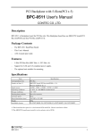
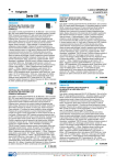
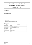
PISA Backplane
PC-BP2/2(PCW) User's Guide
Package Contents
-
The PC-BP2/2(PCW) BackPlane Board
-
This User's Manual
-
ATX Control 6pin Cable
Features
-
4-Slot PISA Backplane
1 X PCI , 1 X PCI/ISA , 1X PISA
-
6-Layes PCB With ATX and AT Power Connectors
-
3.LED Power indicators: +5V, -5V, +12V,-12V and +3.3V
Specifications
Item
Number of slots
Specification
PISA bus slot ×1
PCI bus slot ×1
PCI/ISA bus slot ×1
Operating conditions
0~50ºC, 10~85% (No condensation allowed)
Storage conditions
0~70ºC
Major dimensions (mm)
175.0(L)×132.80(W)×12.0(H)
Weight
210g
Installable unit dimensions
FA-UNIT-F6DR, FA-UNIT-M6RFV, FA-UNIT-F6RFV
Description
PC-BP2/2(PCW) is Backplane board for PISA Bus slot. This Backplane board has one PISA Bus slot,
one PCI Bus slot and one PCI/ISA Bus slot for CPU board. PCI/ISA Bus slot is available to use as PCI
Bus slot or ISA Bus slot.
And INTA of PCI Bus, INTB of PCI Bus are connected to PCI1 slot, PCI2 slot respectively.
-1-
PC-BP2/2(PCW) User's Guide
Board Dimension
132.80
40.60
14.50
40.60
7.50
9.80
7.62
86.40
15.60
11.70
5.30
ISA5
PCI1
ISA4
PCI2
ISA3
ISA2
PCI3
PCI4
ISA1
PISA
CN1
PGD
+5V
+12V
-12V
GND
GND
GND
GND
152.20
155.10
175.00
-5V
+5V
+5V
+5V
CN2
JP1
CN3 CN4
15.57
20.32
15.57
20.32
15.57
20.32
Note!
ISA1~4 and PCI3, 4 slots are not mount.
-2-
15.57
26.68
φ4.0x6
[mm]
PC-BP2/2(PCW) User's Guide
Jumper Setting and Connectors
AT Power Supply Connector: CN1
CN1
1
2
3
4
5
6
7
8
9
10
11
12
PIN No.
Function
1
Power Good
2
+5V
3
+12V
4
-12V
5
GND
6
GND
7
GND
8
GND
9
-5V
10
+5V
11
+5V
12
+5V
Suitable Connector
: GTC6P-1(correspond)
Suitable Socket Contact : PCK18-2TR9(correspond)
Maker
: BURNDY
Option Cables.
(one side is solder disposal)
Type
: PCA-6P2
Model
: Cable length, 36cm(AWG#18), two
ATX Power Supply Connector: CN2
When used with an ATX-compliant power supply that supports remote power on/off, the CPU card can
turn off the system power through software control.
To enable soft-off control in software, advanced power management must be enabled in the Setup
program and in the operation system. When the system BIOS receives the correct APM command from
the operating system, the BIOS turns off power to the computer.
With soft-off enabled, if power to the computer is interrupted by a power outage or a disconnected
power cord, when power resumes, the computer returns to the power state it was in before power was
interrupted (on or off).
CN2
11
20
1
10
PIN No.
Function
PIN No.
Function
11
+3.3V
1
+3.3V
12
-12V
2
+3.3V
13
GND
3
GND
14
PON
4
+5V
15
GND
5
GND
16
GND
6
+5V
17
GND
7
GND
18
-5V
8
Power Good
19
+5V
9
+5VSBY
20
+5V
10
+12V
-3-
Cable side Connector Maker : Molex
Cable side Connector Type : 5557-20R
(39-01-2200)
Cable side Connector
Contact Type
: 5556
PC-BP2/2(PCW) User's Guide
ATX Power Button connector: CN3
CN3
PIN No.
Function
2
GND
1
PBTN
2
1
Housing: XHP-2(JST)
Contact: SXH-001-P0.6(JST)
ATX Power Control Connector: CN4
PIN No.
Function
6
+5V SBY
5
PSOUT
CN4
6
5
4
3
2
1
4
GND
3
PBTN-IN
2
GND
1
PME
PIN No.
Function
3
GND
Housing: XHP-6(JST)
Contact: SXH-001T-P0.6(JST)
ATX Power ON: JP1
JP1
3
2
1
2
PBIN
1
PSOUT
2-3 Short : Disable ATX Power Control and set the
ATX Power Supply ON always by push switch
(use as AT Power Supply). (Default)
1-2 Short : Enable ATX Power Control by push switch.
Connector Block Drawing
JP1
ATX Power Connector
CN2
9
+5VSBY
14
3
2
1
CN4
[Connect to CPU board with 6pin Cable (included).]
6
+5VSBY : +5V Stanby Voltage supplied to CPU board.
5
PS_OUT : ATX Power Supply ON (Low Lebel) Signal from CPU board.
4
GND
PON
3
PCI1, 2
A19
2
PME
1
PBTN_IN : Output Switch Signal (connected to CN3) to CPU board.
GND
PME
: no use on this CPU board.
ATX Power ON/OFF Switch
CN3
2
1
PME:Power Mnagement Enable Signal
GND
PBTN
-4-
PC-BP2/2(PCW) User's Guide
Copyright
Copyright 2000 CONTEC Co., LTD. ALL RIGHTS RESERVED
No part of this document may be copied or reproduced in any form by
any means without prior written consent of CONTEC Co., LTD.
CONTEC Co., LTD. makes no commitment to update or keep current
the information contained in this document. The information in this
document is subject to change without notice.
All relevant issues have been considered in the preparation of this
document. Should you notice an omission or any questionable item in
this document, please feel free to notify CONTEC Co., LTD.
Regardless of the foregoing statement, CONTEC assumes no
responsibility for any errors that may appear in this document nor for
results obtained by the user as a result of using this product.
Limited One-Year Warranty
CONTEC IPC Series are warranted by CONTEC Co., LTD to be free
from defects in material and workmanship for up to one year from the
date of purchase by the original purchaser.
Repair will be free of charge only when this device is returned freight
prepaid with a copy of the original invoice and a Return Merchandise
Authorization to the distributor or the CONTEC group office, from
which it was purchased.
This warranty is not applicable for scratches or normal wear, but only for
the electronic circuitry and original boards. The warranty is not
applicable if the device has been tampered with or damaged through
abuse, mistreatment, neglect, or unreasonable use, or if the original
invoice is not included, in which case repairs will be considered beyond
the warranty policy.
-5-
PC-BP2/2(PCW) User's Guide
How to Obtain Service
For replacement or repair, return the device freight prepaid, with a
copy of the original invoice. Please obtain a Return Merchandise
Authorization Number (RMA) from the CONTEC group office where
you purchased before returning any product.
*No product will be accepted by CONTEC group without the
RMA number.
Liability
The obligation of the warrantor is solely to repair or replace the product.
In no event will the warrantor be liable for any incidental or
consequential damages due to such defect or consequences that arise
from inexperienced usage, misuse, or malfunction of this device.
-6-
PC-BP2/2(PCW) User's Guide
CONTEC Group
JAPAN
: Headquarters
CONTEC Co., LTD.
3-9-31, Himesato, Nishiyodogawa-ku, Osaka 555-0025, Japan
Tel
: +81 (6) 6477-5219
Fax : +81 (6) 6477-1692
E-mail : [email protected]
U.S.A.
: CONTEC MICROELECTRONICS U.S.A. INC.
744 South Hillview Drive, Milpitas, CA 95035 U.S.A.
Tel
: +1 (408) 719-8200
Fax : +1 (408) 719-6750
E-mail : [email protected]
EUROPE
: CONTEC MICROELECTRONICS EUROPE B.V.
Binnenweg 4, 2132 CT, Hoofddorp, The Netherlands
Tel
: +31 (23) 567-3030
Fax : +31 (23) 567-3035
E-mail : [email protected]
KOREA
: HYOJIN CONTEC Co., LTD.
Ki-im Bldg. #399, Shindolim-Dong, Kuro-ku, Seoul, Korea
Tel
: +82 (2) 2636-4277/8
Fax : +82 (2) 2636-4279
E-mail : [email protected]
CHINA
:
INTERNATIONAL CONTEC TECHNOLOGY CO., LTD.
B-8F, Hua Tong Building, No. B19, Che Gong Zhuang West Road,
Hai Dian District, Beijing 100044, China
Tel
: +86(10)8801-8228
Fax : +86 (10)8801-8209
E-mail : [email protected]
SHANGHAI CONTEC MICROELECTRONICS Co., LTD.
No. 481 Gui Ping Road, Cao He Jing Hi-Tech Park Shanghai, 200233, China
Tel
: +86 (21) 6485-1907
Fax : +86 (21) 6485-0330
E-mail : [email protected]
SHENYANG CONTEC MICROELECTRONICS Co., LTD.
No. 169, Qingnian Street, Shenhe District, Shenyang 110015, China
Tel
: +86 (24) 2392-9771
Fax : +86 (24) 2392-9773
TAIWAN
: MACROMATE CORP.
8F, Universal Center, No.179, Ta-Tung Rd., Sec.1 Hsi-Chih, Taipei Hsien, Taiwan,
R.O.C
Tel
: +886 (2) 2647-9353
Fax : +886 (2) 2647-9373
E-mail : [email protected]
-7-
PC-BP2/2(PCW) User's Guide
A-46-434
LZS3941
021018 [001226]
-8-