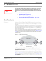
1
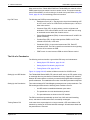
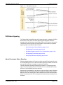
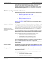
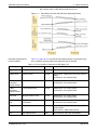
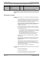
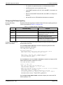
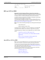
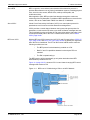
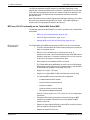
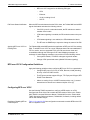
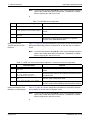
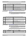
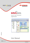
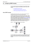
TMOS MPLS Application Manual
11. MPLS Pseudowires
11. MPLS Pseudowires
Return to Main
Page
The Tellabs 8800 TMOS software supports the configuration and monitoring of
pseudowires (PW) in a MPLS-enabled Packet Switched Network (PSN). The
following sections provide background and describe procedures for configuring
PWs:
•
About Pseudowires, page 36-143
•
PW Status Signaling, page 36-145
•
BFD over VCCV for PWE3, page 36-150
•
Configuring Static Multi-Segment Pseudowire, page 36-158
About Pseudowires
Pseudowires
Pseudowire-Emulation-Edge-to-Edge (PWE3) is a mechanism that emulates a
telecommunications service, for example, ATM or Frame Relay, over a variety of
PSN types.
A PWE3 circuit allows traffic originating from customer edge (CE) to traverse the
PSN while maintaining characteristics of a native service. From the perspective of
the customer edge (CE) device, the PW is characterized as an unshared link or
circuit of the chosen service.
A PW is set up between two provider edge (PE) nodes in an MPLS network. The
PE then connects to the CE through an attachment circuit (AC). Figure 11.1, page
36-143 shows the PWE3 Reference Model with two Tellabs 8800 series MSRs
acting PE nodes.
Figure 11.1
PWE3 Reference Model
The Tellabs 8800 Series MSR architecture applies MPLS Label Distribution
Protocol (LDP) and Resource Reservation Protocol (RSVP) to set up and maintain
pseudowires across a network.
A PWE3 circuit consists of two unidirectional flows, shown as PW1 and PW2, in
Figure 11.1, page 36-143. Both sides of the PW must be configured for the PWE3
circuit to be operational. For example, both PE Nodes A and B in Figure 11.1, page
36-143, must be configured for two PWs, A to B and B to A, for the PWE3 circuit
to be operational.
76.880080/36, Rev A, 7/09
Page 36-143
11. MPLS Pseudowires
TMOS MPLS Application Manual
Other sections of the Tellabs 8800 TMOS and Tellabs 8890 user manuals refer to
PWE3-based circuits as martini circuits or remote circuits. This section uses the
terms, PW and PWE3, to refer to this type of virtual circuit path. Refer to Key PW
Terms, page 36-144, for terminology used in this section.
Key PW Terms
The following are PWE3 terms and definitions:
•
Attachment Circuit (AC)—The physical or virtual circuit attaching a CE
to a PE. An AC can be an ATM VPI/VCI, an Ethernet port, a VLAN, or
other native service.
•
Customer Edge (CE)—A device where a service originates and
terminates. In the case of PWE3, the CE is not aware that it is using
an emulated service rather than a native service.
•
Packet Switched Network (PSN)—A network that uses IP or MPLS for
packet forwarding.
•
Provider Edge (PE)—A device that provides PWE3 to a CE. Also
referred to as a node, or PE node.
•
Pseudowire (PW)—A connection between two PEs. Each PE
terminates an AC. The PW is a path for an emulated circuit originating
from the AC to traverse the PSN.
•
PSN Tunnel—A tunnel across a PSN on which PWs are carried.
The Life of a Pseudowire
The following sections describe a generalized PW setup and maintenance:
•
Setting Up an LDP Session, page 36-144
•
Setting Up the Pseudowire, page 36-144
•
Tearing Down a PW, page 36-144
Figure 11.2, page 36-145, outlines a lifetime scenario for a PWE3 circuit.
Setting Up an LDP Session
Two Tellabs 8800 Series MSRs, PE nodes A and B, set up an LDP session using
an extended discovery mechanism. Extended discovery supports LDP sessions
between PE nodes that are not directly connected with targeted hello messages to
specific addresses. This establishes the nodes A and B as pseudowire endpoints.
Setting Up the Pseudowire
The nodes exchange LDP Label Mapping messages to set up the pseudowire. The
PW exchanges labels when the following three conditions are met:
•
An LDP session is established between peer nodes.
•
The pseudowire circuit is administratively enabled.
•
The peer addresses are known to the LDP session.
The PW is considered operationally up when free of AC and local forwarding
errors, and when the labels have been successfully exchanged.
Tearing Down a PW
Page 36-144
In the case where a pseudowire is no longer needed, a PE node initiates a PW
teardown by sending an LDP label withdraw message. All labels associated with
the pseudowire are removed.
76.880080/36, Rev A, 7/09
TMOS MPLS Application Manual
11. MPLS Pseudowires
Figure 11.2
PW Lifetime Scenario
PW Status Signaling
The Tellabs 8800 Series MSR supports PW status signaling, a capability of PWE3s
and the LDP control plane. PW status signaling generates fewer LDP FEC
messages than label withdraw, lessening the impact of CPE faults on the network.
The following sections describe the implementation of pseudowire (PW) status
signaling as part of an MPLS-enabled network:
•
About Pseudowire Status Signaling, page 36-145
•
PW Signaling Functionality, page 36-148
•
PW Status Signaling and the Life of a Pseudowire, page 36-146
•
PW Signaling Functionality, page 36-148
•
Configuring PW Status Signaling, page 36-149
About Pseudowire Status Signaling
PW status signaling allows a PE node to notify its remote PE peer when AC errors
or local forwarding errors occur. When PW status signaling is enabled, the PE node
uses the LDP notification messages to signal error conditions.
The LDP notification message contains the PW Status TLV (type-length-value
tuple). PW status signaling uses the PW Status TLV to convey PW status if any
AC-side or local forwarding errors are detected.
Alternatively, label withdraw can be used for to signal a change in status. With label
withdraw, the PE node withdraws the label for the PW to signal a status change.
When the errors are cleared, the PE then rebuilds the PW, and re-advertises the
labels. This generates LDP FEC messages and increases the processing load on
a network.
76.880080/36, Rev A, 7/09
Page 36-145
11. MPLS Pseudowires
TMOS MPLS Application Manual
Because PW status signaling generates fewer LDP FEC messages than label
withdraw, PW status signaling reduces the processing load in initiating,
terminating, and transit nodes. In addition, PW status signaling enables quicker
PW setup because the initiating PE node does not wait for the ACs to become
active before establishing the PW.
PW Status Signaling and the Life of a Pseudowire
The following sections describe a generalized a PW setup and maintenance with
PW status signaling enabled:
•
Setting up an LDP Session, page 36-146
•
Negotiating PW Status Signaling and Setting Up the Pseudowire,
page 36-146
•
Detecting PW Status, page 36-146
•
Tearing Down a PW, page 36-146
Figure 11.3, page 36-147, outlines a lifetime scenario for a pseudowire with PW
status signaling.
Setting up an LDP Session
Two Tellabs 8800 series MSRs, PE nodes A and B, set up an LDP session using
an extended discovery mechanism. Extended discovery supports LDP sessions
between PE nodes that are not directly connected with targeted hello messages to
specific addresses. This establishes the nodes A and B as pseudowire endpoints.
Negotiating PW Status
Signaling and Setting Up the
Pseudowire
The nodes exchange LDP Label Mapping messages to set up the pseudowire.
With PW status signaling enabled, the nodes exchange Label Mapping messages
regardless of the AC state or LSP availability. The LDP Label Mapping message
includes the PW status code which is used during the lifetime of the pseudowire.
The PW exchanges labels when the following three conditions are met:
•
An LDP session is established between peer nodes.
•
The pseudowire circuit is administratively enabled.
•
The peer addresses are known to the LDP session.
With PW status signaling enabled, the PE nodes attempt to establish the PW even
if the AC is operationally down or if there is a local forwarding error.
Refer to Setting Up the Pseudowire, page 36-144, for a PW setup with PW status
signaling disabled.
Detecting PW Status
During the lifetime of a PW, PW status signaling uses the PW status code to signal
AC errors and local forwarding errors. Refer to PW Status Signaling Error Faults
Conditions, page 36-147, for details on the PW status code.
Tearing Down a PW
In the case where a pseudowire is no longer needed, a PE node initiates a PW
teardown by sending an LDP label withdraw message. All labels associated with
the pseudowire are removed.
With PW status signaling enabled, the PW label is withdrawn only when one or
more of the following conditions occur:
Page 36-146
•
The pseudowire configuration is deleted.
•
The operator disables the pseudowire.
76.880080/36, Rev A, 7/09
TMOS MPLS Application Manual
11. MPLS Pseudowires
•
Figure 11.3
PW Status Signaling Error
Faults Conditions
LDP session down or LDP address down errors occur.
PW Lifetime Scenario with PW Status Signaling Enabled
Table 11.1, page 36-147, lists PW fault descriptions based on pseudowire type,
error conditions, and the network side where the fault is detected.
Table 11.1 Error Conditions Carried in the PW Status TLV
PW Type
Error Condition
Side
PW Fault Description
Any
PW BFD session down
LSP
PW not forwarding
PWE3 circuit
Interface down
Circuit
AcRxFailure—Attachment circuit (AC) receive
failure
AcTxFailure—AC transmit failure
PWE3
redundant
bundle member
Circuit bundle disabled
Circuit
AcRxFailure—AC receive failure
AcTxFailure—AC transmit failure
PWE3
redundant
bundle member
Circuit bundle down
Circuit
AcRxFailure—AC receive failure
AcTxFailure—AC transmit failure
VPLS PW
Bridging instance down
Circuit
AcRxFailure—AC receive failure
AcTxFailure—AC transmit failure
Mirroring target
PW
Target or mirroring instance
not enabled
Circuit
AcRxFailure—AC receive failure
AcTxFailure—AC transmit failure
Any
LSP not found
LSP
PsnRxFailure—Packet switched network (PSN)
receive failure
PsnTxFailure—PSN transmit failure
Any
LDP address down
LSP
No PW status code; label is withdrawn.
76.880080/36, Rev A, 7/09
Page 36-147
11. MPLS Pseudowires
TMOS MPLS Application Manual
Table 11.1 Error Conditions Carried in the PW Status TLV (Continued)
PW Type
Error Condition
Side
PW Fault Description
Any
Circuit is administratively
disabled
N/A
No PW status code; label is withdrawn.
Any
Circuit configuration delete
N/A
No PW status code; label is withdrawn.
If the pseudowire circuit is administratively disabled, or the circuit configuration is
deleted, PW status signaling is not applied and the associated label is withdrawn
instead.
PW Signaling Functionality
PW status signaling functions on a Tellabs 8800 series MSR with the following
conditions:
•
For PW status signaling to be active, both PE nodes on a PWE3 circuit
must support PW status signaling. Although you can configure and
enable PW status signaling on one PE node, notification messages
are not sent until both ends are configured and enabled.
•
If either PE node does not include the PW status in the label mapping
message, then both PE routers revert to LDP Label Withdraw
messages to signal status.
•
The use of group and wildcard notification messages is supported.
This minimizes the number of messages sent when a status change
affects multiple pseudowires.
-
The PW ID field in all LDP PW messages contains a group ID as
well as a specific PW ID. When a message omits a specific PW ID,
the message then applies to all PWs in the group.
-
The Tellabs 8800 series MSR uses the same group ID for all
PWE3 circuits using the same port-side Layer 2 interface.
•
Only single-segment PWs, not multi-segment PWs, can apply PW
status signaling.
•
If you upgrade an existing network that does not support PW status
signaling, PW status signaling remains disabled by default in the
upgraded network.
After upgrading a node and enabling PW status signaling, circuits
created after the upgrade will use PW status signaling. However,
circuits created prior to the upgrade will not use PW status signaling
until after the node is restarted.
•
PW status signaling is supported for all PWE3 types.
The Tellabs 8800 series MSRs report PW status change for any of the following
conditions:
Page 36-148
•
The ULC is operationally down.
•
The PLM is operationally down.
•
The port is operationally down or administratively disabled.
•
The LAG, APS or multilink group is operationally down.
76.880080/36, Rev A, 7/09
TMOS MPLS Application Manual
11. MPLS Pseudowires
•
The interface is operationally down or administratively disabled.
•
An SFP transmit or receive optic fault occurs.
•
Local SONET faults like LOS, LOF, AIS, and NBET, for example, are
detected.
•
Receive remote SONET faults like RDI, AIS, FBET, for example, are
detected.
•
AIS and RDI receive ATM OAM fault indications are detected.
Configuring PW Status Signaling
Enabling PW Status
Signaling
By default, PW status signaling is disabled. Enable PW status signaling globally on
a node, as described in Table 11.2, page 36-149.
Table 11.2 Enable PW Status Signaling
Command Entry
Purpose
Step 1.
8800# enable config protocol mpls ldp
Enter LDP configuration mode.
Step 2.
8800(cfg-mp-ldp)# pw-status-signaling enable
Administratively enable PW status
signaling on a node.
Step 3.
8800(cfg-mp-ldp)# exit all
Exit LDP configuration mode.
Step 4.
8800# show protocol mpls ldp
Display LDP configuration mode to
verify PW status signaling state.
Viewing PW Signaling and
PW/AC Fault Status
The CLI show commands in this section display the status of the PW configuration,
and the status of the PW.
Use the show protocol mpls ldp command to display the global PW status
signaling configuration information.
8800# show protocol mpls ldp
LDP Default Parameters:
Advertisement Mode: unsolicited; Label Retention Mode: liberal
Hello Timer: 15(sec); Targeted Hello Timer: 45(sec)
….
….
Label filter - Host only: True; Loopback only: True
Target Response Mode: enable; QoS Mode: Disabled
Pw status signaling: Enable
Use the show ckt <ckt name> detail or extensive commands to display the PW
status related information related to the circuit.
8800# show ckt name v1 detail
circuit: v1; type: vlan
...
side1: port; in status: up; out status: up
int: ge-1/1/4/1; type: vlan; id: 22; pri: ignore
Signal XC Alarm: disabled;
side2: lsp; in status: Peer not forwarding; out status: Peer not forwarding
dynamic out-lsp: test (Learnt);
out vc-label: 1031, in vc-label:1036
service-type: ethernet; group-id: 3053453313; vc-id: 1031
Pw Status Signaling In Use: Enabled; Sent: Enabled; Remote: Enabled
PW Status Failure Local: notForwarding, acTxFailure
PW Status Failure Remote: acTxFailure, psnRxFailure
Use the show ckt pw-status enable command to display the circuits with PW
status signaling in use.
76.880080/36, Rev A, 7/09
Page 36-149
11. MPLS Pseudowires
TMOS MPLS Application Manual
8800# show ckt pw-status enable
Circuit Name
Type Ad Op out-vclabel*/vcid
----------------- -- -- ----------------vlan1
vlan en dn 1010
vlan42
vlan en up 1023
Total Up: 1; Total Down: 1; Total: 2
BFD over VCCV for PWE3
Bidirectional Forwarding Detection (BFD) over Virtual Circuit Connectivity
Verification (VCCV) is a pseudowire (PW) fault detection mechanism. BFD over
VCCV is an Operations and Maintenance (OAM) failure detection method applied
in an MPLS network to validate the data plane and verify PW connectivity.
In an MPLS network carrying traffic over PWE3s, it is important to quickly detect
PW failures to minimize impact to customer traffic.
The Tellabs 8800 series MSR also supports an operator-initiated LSP ping as a
diagnostic tool to detect PWE3 circuit failures. For details about LSP ping, refer to
Basic Ping and Traceroute Operations, page 36-86.
BFD over VCCV offers the following advantages over LSP ping when detecting PW
faults:
•
Faster detection time
•
Monitors a greater number of PWs
The implementation of both BFD over VCCV and LSP ping in the Tellabs 8800
series MSR provides validation and consistency of data and control planes.
The following topics are available to help configure BFD over VCCV for PWE3
service:
•
About BFD over VCCV for PWE3, page 36-150
•
BFD over VCCV Functionality on the Tellabs 8800 Series MSR,
page 36-152
•
BFD over VCCV Configuration Guidelines, page 36-153
•
Configuring BFD over VCCV, page 36-153
About BFD over VCCV for PWE3
BFD over VCCV uses the BFD protocol as a connectivity verification type over a
VCCV control channel to monitor PW connectivity and quickly detect faults.
The PW uses the Pseudowire Emulation Edge to Edge (PWE3) mechanism to
carry customer traffic across a PSN. Refer to About Pseudowires, page 36-143,
for an explanation of the terms used in this section.
This section provides background information about the protocols used when
implementing BFD over VCCV in the following sections:
Page 36-150
•
About BFD, page 36-151
•
About VCCV, page 36-151
•
BFD over VCCV, page 36-151
76.880080/36, Rev A, 7/09
TMOS MPLS Application Manual
About BFD
11. MPLS Pseudowires
BFD is a generic, low-overhead, short-duration failure detection protocol. It
provides failure detection on any kind of path between systems, including physical
links, virtual circuits, tunnels, MPLS LSPs, multihop routed paths, and
unidirectional links.
When applied to PWs, BFD provides fault detection through the continuous
monitoring of the PW data path. For additional BFD capabilities not covered in this
section, refer to the Tellabs 8800 TMOS User Manual, 76.880080/4.
About VCCV
Virtual Circuit Connectivity Verification (VCCV) is a control plane protocol for
pseudowires to aid in end-to-end fault detection and diagnostics.
VCCV provides a control channel between the ingress and egress points of a
pseudowire, in this case the PE nodes, over which verification messages are sent.
This functionality permits verification of PW connectivity and the data plane used
to transport the data path for the PW. For details about VCCV, refer to About
VCCV, page 36-88.
BFD over VCCV
With the BFD over VCCV protocol, the VCCV CC and CV types (refer to VCCV CC
Type, page 36-88, and VCCV CV Types, page 36-89, for details) are negotiated
when the PW is established. The PE can then initiate a BFD session when the
following conditions are met:
•
The BFD protocol is administratively enabled on a PW.
•
Both CC and CV capabilities between local and peer PEs are
matched.
•
The PW is operationally up.
The BFD session will be operationally up only when both sides have BFD
administratively enabled on a PW.
Figure 11.4, page 36-151, shows a VCCV control channel carrying BFD control
messages that monitor a PW.
Figure 11.4
76.880080/36, Rev A, 7/09
BFD over VCCV Monitoring a PW on an MPLS Network
Page 36-151
11. MPLS Pseudowires
TMOS MPLS Application Manual
The PE node maintains the BFD session by periodically transmitting control
packets after successful establishment of a session. If packets are not received by
a PE within the negotiated time interval, the session to that PE is declared to be
operationally down. The PE assumes the pseudowire has failed, and takes
appropriate action.
Other PE node functions, like alarm reporting and PW status signaling, are notified
about the failure detected through BFD over VCCV. If PW status signaling is
enabled, the PE node signals the status to the PE peer.
BFD over VCCV Functionality on the Tellabs 8800 Series MSR
The following topics describe how BFD over VCCV operates on the Tellabs 8800
series MSR:
BFD over VCCV
Characteristics
•
BFD over VCCV Characteristics, page 36-152
•
PW Down Status Notification, page 36-153
•
Applying BFD over VCCV on Existing PWs, page 36-153
The Tellabs 8800 series MSR implementation of BFD over VCCV is as follows:
•
The PW is declared down when BFD control packets are not received
within a configured interval.
•
BFD over VCCV operates only in asynchronous mode. In
asynchronous mode, a pair of systems periodically sends BFD control
packets to each other. If a number of packets in a row is not received
by the other, the session is declared to be down.
•
Echo function is not available for BFD over VCCV.
•
The Tellabs 8800 series MSR takes an active role as a PW endpoint.
BFD session comes up after the PW is operationally up, and after BFD
is administratively enabled on both sides of the PW.
•
Support for CC type, TTL Expiry.
•
Support for CV types BFD IP/UDP Fault Detection and LSP Ping.
•
The following BFD session parameters are configurable:
-
Enable/Disable the BFD session
-
Desired minimum transmit interval
-
Detection multiplier
-
Required minimum receive interval
-
BFD session established wait time
Refer to Configuring BFD over VCCV, page 36-153, for configuration
procedures.
Page 36-152
•
Changes to BFD session parameters at any time during the BFD
session are permitted, without the need to first disable the BFD
session on the PW.
•
Support for single-segment PWs only, as the BFD over VCCV protocol
does not support multi-segment PWs.
•
Support for dynamic PW circuits.
76.880080/36, Rev A, 7/09
TMOS MPLS Application Manual
11. MPLS Pseudowires
•
PW Down Status Notification
Applying BFD over VCCV on
Existing PWs
BFD over VCCV support for the following PW types:
-
ATM
-
Ethernet
-
VLAN, including Q-in-Q
-
SAToP
When the BFD session detects that the PW is down, the Tellabs 8800 series MSR
signals fault status and takes the following actions:
•
If the PW is part of a redundant bundle, the PE switches to another
member of the bundle.
•
If PW status signaling is enabled, the PE sends the status to the peer
PE.
•
If PW status signaling is not enabled, the PE withdraws the labels.
•
The PE uses an SNMP trap to report the change in status of the PW.
The Tellabs 8800 series MSR permits the application of BFD over VCCV to existing
PWs. To add BFD over VCCV to a set of endpoints where PW was established in
FP7.3 or earlier, and now upgraded FP8.0, the PW must be torn down and
re-established through the exchange of LDP Label Mapping messages. An
exchange of Label Mapping messages occurs with one of the following actions:
•
If the system restarts, or if MPLS undergoes a graceful restart.
•
Change of PW operational status (disable PW status signaling).
BFD over VCCV Configuration Guidelines
Apply the following guidelines when configuring BFD over VCCV on a pseudowire:
•
Configure BFD over VCCV only on ATM, Ethernet, VLAN (including
Q-in-Q), or SAToP PWE3 circuits.
•
The PE peer must also support CC type, TTL Expiry and CV type, BFD
IP/UDP Fault Detection.
•
Adhere to scaling of up to 100 BFD sessions with a one (1) second
transmit/receive interval and a detect multiplier of five (5).
Configuring BFD over VCCV
Use the following TMOS commands to configure a BFD session on a PW.
Configure both ends of the PW to enable the BFD session. Refer to the Tellabs
8800 TMOS Command Reference Manual, 76.880080/5, and the Tellabs 8800
TMOS Operations Reference Manual, 76.880080/6, for details, including default
values and available ranges.
Enabling or Disabling BFD on
a PW Endpoint
76.880080/36, Rev A, 7/09
Table 11.3, page 36-154 lists configuration commands to enable BFD on the LSP
side of a dynamic circuit.
Page 36-153
11. MPLS Pseudowires
TMOS MPLS Application Manual
Note:
This procedure assumes that side id 1 of the circuit is already configured.
Refer to the Tellabs 8800 TMOS User Manual, 76.880080/4, for details
about configuring this side of the circuit.
Table 11.3 BFD Minimum Configuration
Command Entry
Purpose
Step 1.
8800# enable config
Enter the configuration mode.
Step 2.
8800(config)# ckt name ckt12 side id
2 lsp dynamic-ckt bfd admin enable
Enable BFD over VCCV for the LSP side of a dynamic
circuit.
Step 3.
8800(cfg-ckt-side-bfd [ckt12:2])#
exit all
Exit the circuit configuration mode.
Step 4.
8800# show ckt name ckt12 detail
Display BFD configuration parameters for a dynamic
circuit to verify administrative state.
Setting the Minimum
Transmit Interval of a PW
Endpoint
Table 11.4, page 36-154 lists configuration commands to set the desired minimum
BFD packet transmitting interval, in milliseconds, on the LSP side of a dynamic
circuit.
Note:
This procedure assumes that side id 1 of the circuit is already configured.
Refer to the Tellabs 8800 TMOS User Manual, 76.880080/4, for details
about configuring this side of the circuit.
Table 11.4 BFD over VCCV Packet Desired Minimum Transmission Interval Configuration
Command Entry
Step 1.
8800# enable config ckt name ckt12
Purpose
side id 2
Enter the LSP side of the dynamic circuit configuration
mode.
Step 2.
8800(cfg-ckt-side [ckt12:2])# side
id 2 lsp dynamic-ckt bfd
desired-min-tx-interval 100
Set the desired minimum BFD packet transmitting interval
in milliseconds.
Step 3.
8800(cfg-ckt-side [ckt12:2])# exit
all
Exit the circuit configuration mode.
Step 4.
8800# show ckt name ckt12 detail
Display BFD configuration parameters for a dynamic
circuit to verify minimum BFD packet transmission interval.
Setting the Detection Time
Multiplier of a PW Endpoint
Table 11.5, page 36-155 lists configuration commands to set the BFD detection
time multiplier on the LSP side of a dynamic circuit.
Note:
Page 36-154
This procedure assumes that side id 1 of the circuit is already configured.
Refer to the Tellabs 8800 TMOS User Manual, 76.880080/4, for details
about configuring this side of the circuit.
76.880080/36, Rev A, 7/09
TMOS MPLS Application Manual
11. MPLS Pseudowires
Table 11.5 BFD over VCCV Detection Time Multiplier Configuration
Command Entry
Purpose
Step 1.
8800# enable config enable config
ckt name ckt12 side id 2
Enter the LSP side of the dynamic circuit configuration
mode.
Step 2.
8800(cfg-ckt-side [ckt12:2]# lsp
dynamic-ckt bfd detect-multiplier 5
Set the BFD detection time multiplier.
Step 3.
8800(cfg-ckt-side [ckt12:2])# exit
all
Exit the circuit configuration mode.
Step 4.
8800# show ckt name ckt12 detail
Display BFD configuration parameters for a dynamic
circuit to verify detection time multiplier.
Setting the Minimum Receive
Interval for BFD Control
Packets at a PW Endpoint
Table 11.6, page 36-155 lists configuration commands to set the required
minimum receive interval, in milliseconds, for BFD packets on the LSP side of a
dynamic circuit.
Note:
This procedure assumes that side id 1 of the circuit is already configured.
Refer to the Tellabs 8800 TMOS User Manual, 76.880080/4, for details
about configuring this side of the circuit.
Table 11.6 BFD over VCCV Required Minimum Receive Packet Interval Configuration
Command Entry
Step 1.
Step 2.
8800# enable config enable config
ckt name ckt12 side id 2
8800(cfg-ckt-side [ckt12:2]# lsp
Purpose
Enter the LSP side of the dynamic circuit configuration
mode.
dynamic-ckt bfd
required-min-rx-interval 500
Set the required minimum interval, in milliseconds,
between received BFD control packets that the PE is
capable of supporting.
Step 3.
8800(cfg-ckt-side [ckt12:2])# exit
all
Exit the circuit configuration mode.
Step 4.
8800# show ckt name ckt12 detail
Display BFD configuration parameters for a dynamic
circuit to verify minimum BFD packet receive interval.
Setting the BFD Session
Timeout for a PW Endpoint
Table 11.7, page 36-155 lists configuration commands to set the BFD session
timeout on the LSP side of a dynamic circuit.
Note:
This procedure assumes that side id 1 of the circuit is already configured.
Refer to the Tellabs 8800 TMOS User Manual, 76.880080/4, for details
about configuring this side of the circuit.
Table 11.7 BFD over VCCV Session Timeout Configuration
Command Entry
Step 1.
8800# enable config enable config
ckt name ckt12 side id 2
76.880080/36, Rev A, 7/09
Purpose
Enter the LSP side of the dynamic circuit configuration
mode.
Page 36-155
11. MPLS Pseudowires
TMOS MPLS Application Manual
Table 11.7 BFD over VCCV Session Timeout Configuration (Continued)
Command Entry
Step 2.
Purpose
8800(cfg-ckt-side [ckt12:2]# lsp
Sets the amount of wait time, in seconds, that an attempt
to establish a BFD session to the peer node is made.
Once the timer expires, the session is declared down and
the clients associated with the session will be notified.
dynamic-ckt bfd
session-est-wait-timeout 10
The session established wait time can be configured as
0. When set to 0, attempts to establish the session with
the peer does not cease and the BFD session status of
Down is never sent to client, until such time after
successfully establishing the session for the first time.
The default value for this parameter is 0.
Step 3.
8800(cfg-ckt-side [ckt12:2])# exit
all
Exit the circuit configuration mode.
Step 4.
8800# show ckt name ckt12 detail
Display BFD configuration parameters for a dynamic
circuit to verify BFD session timeout interval.
Viewing PW Signaling and
PW/AC Fault Status
The CLI show commands in this section display the status of the BFD
session-related information.
Use the show protocol bfd session command to view all applications and
interfaces, including those with BFD over VCCV sessions.
8800# show protocol bfd session
Application:Ip(ipv4)
Legend: O - OSPF, I - ISIS, B - BGP, S - Static Route
Detect Time
lcl/rmt
Interface
Ip Address
Client[s] (msec)
-------------------------- ----------ge-1/8/1/1.1
2.1.1.2
O
300/300
so-1/8/3/1:1.1
4.1.1.2
O
300/300
Op
St
-up
up
Application:Mpls
Legend: Pri - RSVP Primary Path, Bkup - RSVP Backup Path,
Byp - RSVP Bypass Tunnel, vccv - BFD sessions over vccv.
Detect time
Lsp Name/
lcl/rmt
Ckt Name
Fec(to)
(msec)
Sig
-------------------------24atm1
24.24.24.24
5000/5000
VCCV
24eth1
24.24.24.24
5000/5000
VCCV
24vlan1
24.24.24.24
5000/5000
VCCV
satop
24.24.24.24
5000/5000
VCCV
37atm1
37.37.37.37
5000/5000
VCCV
24eth2_vbrrt
24.24.24.24
5000/5000
VCCV
37vlan1
37.37.37.37
5000/5000
VCCV
37qinq
37.37.37.37
5000/5000
VCCV
elspto37
37.37.37.37/32
5000/300
Pri
LDP_24.24.24.24/32l
24.24.24.24/32
5000/300
LDP
LDP_24.24.24.24/32o
24.24.24.24/32
5000/300
LDP
LDP_24.24.24.24/32p
24.24.24.24/32
5000/300
LDP
Total Up: 14;
Total Down: 0;
St
-up
up
up
up
up
up
up
up
up
up
up
up
Op
Role
---actv
actv
actv
actv
actv
actv
actv
actv
actv
actv
actv
actv
Total: 14
Use the show protocol bfd session vccv detail or extensive command to
display the BFD over VCCV session information for both local and remote PW
endpoints.
8800# show protocol bfd session vccv extensive
Application: Mpls
Circuit Name: 24atm1; Type: VCCV: Circuit Type: atm
Circuit Dest Addr: 10.10.1.2; Oper Status: Up; VcId: 1100
Out Lsp Name: LDP_10.10.1.2/32o; Last incoming Intf: none
Page 36-156
76.880080/36, Rev A, 7/09
TMOS MPLS Application Manual
11. MPLS Pseudowires
Role: active
------Version
Remote heard
Discriminator
Min tx interval(msec)
Detect multiplier
Min rx interval(msec)
Negotiated tx interval
Detection time
Local
----1
yes
0x14000020
1000
3
1000
1000
3000
Remote
-----1
yes
0x10000098
1000
3
1000
1000
3000
Last packet [06/10/2009 18:30:12]:
v=1 diag=No diagnostic sta=Up P=0 F=0 C=0 A=0 D=0 R=0
Mult=3 len=24 My=0x10000098 Your=0x14000020 Tx=1000000 Rx=1000000 echoRx=0
Use the show ckt <ckt name> detail or extensive commands to display all BFD
configured parameters against the circuit, including the CC and CV values
negotiated between the local and peer PEs.
8800# show ckt name vlan1 detail
circuit: vlan1; type: vlan
Indv Trap: enable; MTU check: disable
admin: enable; oper: up; failure reason: none
forwarding status: forwarding;
side1: port; in status: up; out status: up
int: ge-1/1/3/1; type: vlan; id: 1; pri: ignore
Signal XC Alarm: disabled;
side2: lsp; in status: up; out status: up
dynamic out-lsp: LDP_1.1.1.1/32 (Learnt);
out vc-label: 1031, in vc-label:1044
group-id: 268500992; vc-id: 1
Pw Status Signaling In Use: disabled; Sending: disabled; Remote: disabled
Remote in-use CC: TTL expiry,
Local CC: TTL expiry,
Local CV: LSP ping, BFD IP/UDP fault det
Remote CC: TTL expiry,
Remote CV: LSP ping, BFD IP/UDP fault det
BFD parameters:
Detect mult: 3; Desired min tx interval: 100 msec
Required min rx interval: 100 msec; Session establish time: 0 sec
Admin: enabled; Oper: up; Failure reason: none
Auto optimize mode: disabled; Lsp pref: ip-disable
dest: 1.1.1.1; preference: all
lsp L2 intf: pos; avg pkt size: 1518
negotiated MTU: local: 1496; remote: 1496
lsp cac bandwidth: 0(Min), 0(Max)
L2IfSlotId: 1; Out Label: 1024; Out Intf: ge-1/3/3/4.1; DownStream:
1.1.1.1
Use the show protocol bfd session stats command to display BFD session
specific statistics.
8800# show protocol bfd session stats
Application: Mpls
Circuit Name: vlan50; Discriminator: 0x14000004
Last up: 07/07/2009 10:18:19; Last poll: not available
Last down: not available; [No diagnostic]
Session up count: 1
Statistics last cleared: not available
Control Packet Statistics:
-------------------------Sent:
62528
Received: 62530
Use the show protocol bfd global-stats command to display BFD packet
statistics.
8800# show protocol bfd global-stats
Global Control Packet Statistics:
Sent: 2844625
Rcvd: 5571001
Accepted: 2785426
Packet Discard Reason Statistics:
Bad Version
: 0
76.880080/36, Rev A, 7/09
Page 36-157