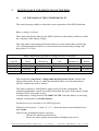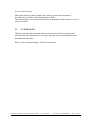
1
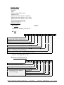
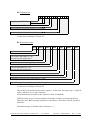
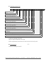
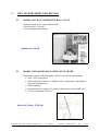
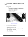
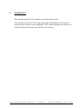
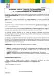
ELTA /
LOCALISATION &
DATA COLLECTION
INSTALLATION, OPERATING
AND 1st LINE MAINTENANCE
INSTRUCTIONS
FOR
PM36 Water Level & Quality
PLATFORMS
Reference:99D9009a.doc
Rev: A
DISTRIBUTION
Copies
Recipient
1
PM36 for Level &
Water Quality
Measurements
Written by:
Copies
Checked by:
Recipient
Approved by:
Copies
Recipient
Issue date: November, 15th
Y. FAURE
K. DUPIN
T. PORTES
QA B.DROXLER
[email protected]
[email protected]
[email protected]
THIS DOCUMENT IS THE PROPERTY OF ELTA. IT SHALL NOT BE COPIED WITHOUT PRIOR
WRITTEN PERMISSION FROM THE OWNER
FORM: IC-6904 Rev C
ARCHIVE No.:
PAGE: 1/39
TABLE OF REVISIONS
Issue
A
Date
15-11-99
Description & Reason
for modification
Sections
affected
Original document.
PM36 for Hydrology and Water Quality Meas.
User Manual
Document : 99D9009a.doc
Rev : A 2/39
TABLE OF CONTENTS
TABLE OF REVISIONS ............................................................................................................................................2
TABLE OF CONTENTS ............................................................................................................................................3
CAUTION ....................................................................................................................................................................4
1.
OPERATION OF THE PM36 PLATFORMS..............................................................................................5
1.1
DESCRIPTION OF THE EQUIPMENT ......................................................................................................5
1.2
DEFINITIONS OF MEASUREMENT CHANNELS AND PERIODS ........................................................7
1.3
DATA STORAGE FRAME ..........................................................................................................................9
1.4
MEMORY CARD READER ......................................................................................................................14
1.5
METEOSAT CREX DATA TRANSMISSION ..........................................................................................16
1.6
DIRECT USER INTERFACE.....................................................................................................................20
1.7
COMPOSITION OF A PM36 .....................................................................................................................27
1.8
SPOT CHECKS TO BE CARRIED OUT BEFORE INSTALLATION.......................................................27
1.8.1
In the laboratory..................................................................................................................................28
1.8.2
Calibration of sensors .........................................................................................................................28
1.8.3
Outdoors, before leaving for the site ...................................................................................................30
1.9
POWER SUPPLY OF THE PM36 PLATFORM........................................................................................31
2.
INSTALLATION OF THE EQUIPMENT .................................................................................................31
2.1
2.2
2.3
3.
MAINTENANCE AND SERVICING OF THE PM36...............................................................................34
3.1
3.2
4.
ON THE BASIS OF THE STORED RESULTS.........................................................................................34
IN THE FIELD............................................................................................................................................35
PH36 TILT PLATFORM SPECIFICATIONS...........................................................................................36
4.1
4.2
5.
ENVIRONMENTAL SPECIFICATIONS ..................................................................................................36
ELECTRICAL SPECIFICATIONS ............................................................................................................36
PM36 SENSORS BRIEF DESCRIPTION ..................................................................................................38
5.1
5.2
5.3
5.4
6.
INSTALLATION OF THE SOLAR PANEL..............................................................................................31
INSTALLATION OF THE PM36 PLATFORM ........................................................................................31
PM36 CONFIGURATION SHEET ............................................................................................................32
MODEL 6011-B QUALIMETRICS RAIN GAUGE ............................................................................................38
MODEL FMX160-2M E&H WATER LEVEL PROBE .....................................................................................38
MODEL SA8065 B&C WATER QUALITY MULTIPARAMETER PROBE ...........................................................39
MODEL TU7685/TU810 TURBIDITY ..........................................................................................................39
WARRANTY .................................................................................................................................................40
PM36 for Hydrology and Water Quality Meas.
User Manual
Document : 99D9009a.doc
Rev : A 3/39
CAUTION
This equipment contains circuits and components which are sensitive to static electricity.
Any operation requiring the handling of the electronic circuit board should be be carried
out at a protected work station.
The PM36 equipment is designed to enable the following operations on site:
! standard exchange of some unit such as the memory cartridge,
! implementation of new sensors systems including probes, connection devices, internal
and external cables,
! replacement of the software memory component. This operation requires special
precautions and appropriate tools must be used, as listed in this manual.
For any advice concerning these operations, whether carried out on site or at a protected
work station, please contact ELTA Division LCD Toulouse (Service Dept. Phone: +33 561.163.230, Fax: +33 561.163.231 or Email: [email protected]).
For storage, the equipment should be kept in a dry and temperate area (15 to 40 °C) and in
its original packing.
PM36 for Hydrology and Water Quality Meas.
User Manual
Document : 99D9009a.doc
Rev : A 4/39
1.
OPERATION OF THE PM36 PLATFORMS
1.1
DESCRIPTION OF THE EQUIPMENT
The PM36 for Level and Water Quality measurements platform is an automatic and
self-contained system which records rainfall, level variations and quality
measurements issued from a multi-parameter probe.
Data frames are stored on an amovible 1 Megabyte memory module.
Le PM36 can also transmits its data via Meteosat geostationnary satellite in CREX
code according to Med-Hycos and SADC-Hycos format.
A low power consumption and a high reliability are achieved thanks to a specific
electronic board, the PM36 board, which allows not only the connection of sensors
but as well the lead battery regulation.
Thanks to the software adapted, this new platform brings an easy solution to
measure water parameters.
The PM36 platform initialises itself automatically each time it is energised.
However, the operator can modify its configuration on site by means of the user
operator interface.
The smooth running of the PM36 platform can be easily checked out on site by the
operator, thanks to keybord-display integrated and the the field terminal for
initializing the multi-parameter probe.
PM36 for Hydrology and Water Quality Meas.
User Manual
Document : 99D9009a.doc
Rev : A 5/39
General synoptic and wiring scheme :
Coffret externe
Panneau Solaire
20 W
Coffret interne
Carte PM36
+
1
2 P2
52
6
ON/OFF
+
1
3
2 P2
J21 2
0
5
6
L
1
P1 J11
2
N
-
J2
P1 J1
30
0V
+ Panneau
+ Batterie
0V
Batterie
38 Ah
Pluviomètre
15 m
J41N
1
2 P9
J41 2
2
Noir
Rouge
FMX 160
Niveau
1
2
Jaune/Vert
L
L
N P4
1
2 P4
0
1
1
4 P9
2
3
0
4
4
Bleu
Vert
Rouge
Noir
1
2 P5
32
4
J4
Pulse
+ Alim.
J9
Retour boucle
+ Boucle
4
2
1
1
2 P5
30
4
J16
1
2 P9
29
J11
+ 12 V
0V
2
4 P6
50
J15
Signal
0V
0V
J51 2
3
4
0V
Multiparamètres
Qualité
+ 12 V
0V
B RS485
A RS485
1K
Su
bD
9
pts
2
3
5
4
6
7
8
L
N P3
2
Rouge (7)
17
Vert (6)
18
Bleu (4)
19
L
J31N
Convertisseur
12V/220V
Jaune
Bleu
1
3
Bleu
3
4
Marron (5) 21
Jaune (1)
Tresse (0)
Sonde
turbidité
22
23
Blanc (3)
24
Gris (2)
25
Noir
14
16
P6 J61
12
6
2
Blanc Rouge
Bleu
3
4
5
1
6
2
Rouge Noir
Blanc
Turbidité
contrôleur
PM36 for Hydrology and Water Quality Meas.
User Manual
Document : 99D9009a.doc
Rev : A 6/39
1.2
DEFINITIONS OF MEASUREMENT CHANNELS AND PERIODS
The PM36 acquisition board measures :
4 multiplexed analog input channels distributed as follows :
"
"
"
"
"
"
"
"
not used,
Channel 1 for PT100 sensor……
Channel 2 for level voltage < 100 mV …… not used,
Channel 3 dedicated to the water level sensor FMX160,
Channel 4 dedicated to the turbidity sensor connected in 4-20 mA loop,
not used,
Channel 5 for current loop or voltage….
Channel 6 for rainfall pulses,
Channel 7 for the serial multi-parameter quality probe,
not used.
Channel 8 for serial connection….
More internal measurements for :
" battery voltage,
" board components temperature indication.
Definition of periods :
Except the rain which is continuously sampled, each channel is sampled at a S
individual and programmable period.
S can take the following values : 1, 5, 6, 15, 30 minutes, 1, 3, 6, 12, 24 hours.
Default value : 1 hour.
In Med-Hycos project, period S is also used to compare variations measurements to
internal thresholds programmed into the platform. If the variation is higher
(increasing or discreasing) than the threshold, a storage of the concerned parameter
happens directly on the amovible module.
The samples are computed at a representative and commun programmable period P
necessary in meteorology for means, maximums, …
P can take the following values : 6, 15, 30 minutes, 1, 3, 6, 12, 24 hours.
Default value : 1 hour.
PM36 for Hydrology and Water Quality Meas.
User Manual
Document : 99D9009a.doc
Rev : A 7/39
Limits :
P is always superior or equal to the highest S period and must be a multiple of all
used S periods.
The internal memory of the PM36 board limits some pairs of (P,S). The spreadsheet
after decribes unauthorized values of (P,S).
P/S ratio:
P \ S
6mn
15mn
30mn
1h
3h
6h
12h
24h
1mn
6
15
30
60
180
360
720
1440
5mn
3
6
12
36
72
144
288
6mn
1
15mn 30mn
5
10
30
60
120
240
1
2
4
12
24
48
96
1
2
6
12
24
48
1h
3h
6h
12h
24h
1
3
6
12
24
1
3
4
8
1
2
4
1
2
1
The grey cells are not possible. For instance, the user can not choose P = 24 h, S = 1
minute.
The software controls forbidden pair values.
Warming time before measurement (not programmable):
- for the multi-parameter quality probe B&C SA8065 (channel 7)
- for the turbidity controler and probe TU7685/TU810 (channel 4)
- for the analog water level sensor (channel 3)
1 minute,
25 seconds,
35 seconds.
The computed values are stored on the amovible memory module at a programmable
period E, in the limit of the capacity of the memory module (1 Megabyte).
E can take the following values : 6, 15, 30 minutes, 1, 3, 6, 12, 24 hours.
Default value : 1 hour.
For Med-Hycos project, E is used to store all blocks of parameters which have
varied between S period. It is only a period to reduce power consumption.
This temporaly buffer is stored at E period or if it is full.
The data storage is not cyclic and when the module is full, it stops.
Then data must be read thanks to the furnished reader linked to a PC computer. The
computer creates an ASCII file compatible with the most well-known speadsheet
calculator : Excel,...
PM36 for Hydrology and Water Quality Meas.
User Manual
Document : 99D9009a.doc
Rev : A 8/39
Data security access on memory module :
The PM36 platform can not write data on another memory module which is not
already in use on the platform : this memory module can come from another
platform, can also be not free of data,…
The « put into use » functionnality accessible with the display-keyboard of the
platform avoids manipulation mistakes.
The PM36 software checks before writing data the serial number of the memory
module AND the free space which is the same as at the end of the preceding
storage.
The PM36 software allows to clear the whole memory module in use. Be careful !
Between 2 storages the user can withdraw the memory module without problems.
1.3
DATA STORAGE FRAME
Med-Hycos Platforms :
Data are stored according variabilities of the parameters at each end of S period.
# either :
- platform identifier ( IDENT ) on 5 bytes (from 00000 to 99999 ) followed by a
space 20h,
# or a dat block including :
- datation ( AAMMJJ HH:MN ) on 12 bytes followed by a space 20h,
- Sensors measurements :
- measurement identifier including 2 descriptive bytes and the input channel number
on 2 bytes,
- measurement ( +yy...y ou yy..y ) in the defined format depending on sensor type,
A space 20h seperate each measurement.
The block is finished by 2 characters CR 0Dh and LF 0Ah.
PM36 for Hydrology and Water Quality Meas.
User Manual
Document : 99D9009a.doc
Rev : A 9/39
Example of a stored block which contains 2 parameters higher than the variability
thresholds :
AAMMJJ HH:MN HHxx +yyyy RRnn yyy
$
%
&
'
%
(
12345
960528 11:05 HH03 +0007 RR06 000000
960528 12:00 RR06 000010
32564
960528 15:11 HH03 +0007 RR06 000030
960529 12:00 HH03 +0010
$ Platform identifier
% First Acquisition of each sensor : the first line after writing platform identifier
& Storage on detected rain
' New platform identifier
( Storage on water level HH overtaking
Storage condition on Water level measurement :
A storage of HHxx occurs when :
- the difference between the last acquired value and the acquired value at the
precedent period S is higher than the programmed threshold,
- OR if the difference between the last acquired value and the last stored value is
higher than the programmed threshold.
These conditions allows to keep in memory either a low rising (or descent) inflow or
a serated rising (or descent) inflow.
Quick upcreasing and discreasing
Low upcreasing (and low discreasing)
Measurements
Measurements
Storage
threshold
Storage
threshold
Storage
Storage
PM36 for Hydrology and Water Quality Meas.
Time
User Manual
over storage
threshold
Storage
Storage
Document : 99D9009a.doc
Time
Rev : A 10/39
About storage conditions :
These conditions can be cancelled by programming 0 in the selected threshold.
Quality Measurement Platforms (Verseau example) :
The stored blocks are :
# either :
- platform identifier ( IDENT ) on 5 bytes (from 00000 to 99999 ) followed by a
space 20h,
# or a dat block including :
- Datation ( AAMMJJ HH:MN ) on 12 bytes followed by a space 20h,
- Sensors measurements :
- Measurement ( +yy...y ou yy..y ) in the defined format depending on sensor type.
A space 20h seperate each measurement.
The block is finished by 2 characters CR 0Dh and LF 0Ah.
Included measurements :
Rain
Water level
Water temperature
Conductivity
PH
Redox voltage
Dissolved Oxygen
Turbidity
PM36 board temperature
Battery voltage
Type of Measurement
Total cumulative count
Average on P
Average on P
Average on P
Average on P
Average on P
Average on P
Average on P
Average on P
Average on P
PM36 for Hydrology and Water Quality Meas.
User Manual
Unité
0,1 mm
Cm
0,1 °C
10 µS
0,1 pH
Millivolt
0,1 mg/l
0,001 NTU (A: 0/4.000 NTU)
0,01 NTU (B: 0/40.00 NTU)
0,1 NTU (C: 0/400.0 NTU)
NTU (D: 0/4000 NTU)
°C
0,1 V
Document : 99D9009a.doc
Gamme
0 / 9999999
-9999 / +9999
-50 / +550
-6000 / +6000
-20 / +160
-1100 / +1100
0 / 200
0 / 4000
-10 / +70
0 / 300
Rev : A 11/39
Message :
AAMMJJ HH:MM 9999999 +/-9999
Datation
$
%
+/-999
+/-9999
+/-999
+/-9999
&
'
(
)
999 X9999 +/-99
999 CrLf
*
-
+
,
$ Rain (0,1mm unit, on 7 bytes),
% Water level (cm unit, on 5 bytes),
& Water temperature (0,1°C unit, on 4 bytes),
' Water conductivity (10µS unit, on 5 bytes),
( Water pH (0,1pH unit, on 4 bytes),
) Water Redox voltage (mV unit, on 5 bytes),
* Water dissolved oxygen (0,1mg/l, on 3 bytes),
+ Water turbidity (on 5 bytes : 1 for the range and 4 for the measurement)
A9999 : 0.001 NTU for a range 0/4.000 NTU,
B9999 : 0.01 NTU for a range 0/40.00 NTU,
C9999 : 0.1 NTU for a range 0/400.0 NTU,
D9999 : 1 NTU for a range 0/4000 NTU.
, PM36 component temperature (°C unit, on 3 bytes),
- Battery voltage (0,1V unit, on 3 bytes).
Total message length : 67 bytes including spaces and CR, LF.
The order is always the same.
When a missed value of a sensor ocuurs, this is replaced by / characters , the
number depends on number of bytes.
Either on Reset of the PM36 (power supply ON) or on memory module
replacement/erasing, the PM36 writes the Identifier of the platform and then, do a
serial of measurements in order to write the first dated block.
After, a storage frame is stored at E period and so on.
Example of a storage frame :
$
00000
990101 00:02 0000000 +0003 +246 +0000 +115 -0338 121 ///// +39 141 %
&
12345
990101 00:11 0000002 +0003 +245 +0000 +116 -0326 123 ///// +39 140 '
990101 01:00 0000006 +0002 +247 +0000 +114 -0307 120 D2552 +40 142 (
PM36 for Hydrology and Water Quality Meas.
User Manual
Document : 99D9009a.doc
Rev : A 12/39
$ Platform identifier 00000,
% First sensors acquisition :
Measurements 01/01/99 00:02 : (rain : 0mm), (level : 3cm), (temperature : 24,6°C),
(conductivity : 0mS), (pH : 11,5pH), (Redox : -338mV), (dissolved oxygen : 12,1mg/l),
(turbidity : measurement out of order), (PM36 temperature : 39°C), (battery voltage :
14,1V),
& New platform identifier
' First sensors acquisition :
Measurements 01/01/99 00:11 : (rain : 0,2mm), (level : 3cm), (temperature : 24,5°C),
(conductivity : 0mS), (pH : 11,6pH), (Redox : -326mV), (dissolved oxygen : 12,3mg/l),
(turbidity : measurement out of order), (PM36 temperature : 39°C), (battery voltage :
14,0V),
( Storage at E (last period P) :
Measurements 01/01/99 01:00 : (rain : 0,6mm), (level : 2cm), (temperature : 24,7°C),
(conductivity : 0mS), (pH : 11,4pH), (Redox : -307mV), (dissolved oxygen : 12,0mg/l),
(turbidity : 2552NTU D: range 0/4000NTU), (PM36 temperature : 40°C), (battery voltage :
14,2V).
Capacity of the memory module :
The PM36 platform can store up to 1 megabyte of data frames.
With 67 bytes per frame, 1 storage per hour, the capacity of the module allows up to
650 days.
When the memory module is full, the storage stops.
PM36 for Hydrology and Water Quality Meas.
User Manual
Document : 99D9009a.doc
Rev : A 13/39
1.4
MEMORY CARD READER
After to have link the Memory reader to the serial port of the PC computer and
thanks to the MEMOWIN software running on PC computer (Win 95, Win 3.1),
the user can retrieve its data.
The data are exchanged through the serial line COM1 of the PC computer at a
maximum speed of 115.2 Kbps.
The user can read his memory cartridges and store the data in a file and export them
to a spreadsheet compatible with Excel for example.
Be careful ! :
It is important to use the delivered adaptator to connect and supply the
MEMO-DRIVE.
Running the MEMOWIN software :
1. First of all, install it if it does not execute from Windows « SETUP » on the disk
A:,
2. Click in the bottom of the main display and if the reader is connected the user can
read « MEMO DRIVE »
3. Then the user can access to the cartridge inserted in the reader for read or to erase
it. This can be done by following the instructions given through the MEMOWIN
software.
Lecteur MEMO-BOX
PM36 for Hydrology and Water Quality Meas.
User Manual
Document : 99D9009a.doc
Rev : A 14/39
Option
220 VAC Line / 12 VDC - 500 mA
Sub D
DTE RS232C
Memory Card Reader Unit
Synoptic
Jack
1.5 m
Connexion
12 VDC / 5 VDC
P1
P1
Memory
Card Reader
6
22
1
4
12
24
18
16
10
8
+ 12 V
Regulator
To power supply
0V
5
3
2
6
4
8
0V
TxD
RxD
DSR
DTR
CTS
To DCE PC
1 MBytes
Flash memory card
TILT7.DRW
PM36 for Hydrology and Water Quality Meas.
User Manual
Document : 99D9009a.doc
Rev : A 15/39
1.5
METEOSAT CREX DATA TRANSMISSION
MED-HYCOS platforms transmits CREX-FM95-XI data every 3 hours.
The P period is intentionally fixed at 1 hour and then a CREX message includes 3
blocks.
Message CREX
CREX++
T000101 A000 D05009++
Identification line code D01029
Identification line for measurements, codes D01012, B0465 et R01000
Measurement line number 1, code D05008
Measurement line number 2, code D05008
Measurement line number 3, code D05008
Supplementary technologic parameters
End of message line (EOM : 7777)
Unit
D01029
Identifier
B01018 :
B02001 :
D01011
Date
WMO station identifier
Type of station
B04001 : Year
B04002 : Month
B04003 : Day
Hour (HH) of the first measurements
D01012
B04004 :
Time (HHMM)
of the first
D05009
B04005 : Minutes (MM) of the first mesurements
measurements
B04065 : Time increment
R01000 : Repeating time of the next line (n=3)
B13072 : Water level
D05006 B13082 : Water temperature
One
B13019 : Last hour rain
D05008
Measurement
measure- B12073 : Air temperature
line
ment
B13073 : Maximum water level (on P period)
B13060 : Cumulative rain
Soil
temperature
B12031 :
Bytes
5
1
4
2
2
2
2
minutes
cm
0,1 K
0,1 mm
0,1 K
cm
0,1 mm
0,1 K
2
4
4
4
4
4
4
5
4
Following these data, the PM36 software place technologic parameters.
PM36 for Hydrology and Water Quality Meas.
User Manual
Document : 99D9009a.doc
Rev : A 16/39
Detailed codage :
- Headline,
- Data,
- Platform identification line,
- Definition line,
- Measurement line number 1 (H hour),
- Measurement line number 2 (H-1 hour),
- Measurement line number 3 (H-2 hour),
- Technology parameters line,
- End of message line (7777).
Definition of lines :
. Headline :
CREX++
8 characters, including 'CR' and 'LF'.
/ Data :
T 0 0 0 1 0 1
A 0 0 0
D 0 5 0 0 9 + +
N° of master CREX table (00 =
standard CREX table (WMO FM 95))
Table edition
CREX version
Reference of the table A, CREX format
N° of reference code of the D table
(class 5 : Hydrology et Meteorology)
N° of sequence in the class 5 : data format description
23 bytes, including 'CR' and 'LF'.
0 Platform identification line :
6 8 0 1 9
0
1 9 9 6
0 7
0 2
Identification platform number
Station type
Acquisition CREX datation
(last H message)
Millenium
Year
Month
Day
20 characters, including 'CR' and 'LF'.
PM36 for Hydrology and Water Quality Meas.
User Manual
Document : 99D9009a.doc
Rev : A 17/39
1 Definition line :
0 1
Acquisition CREX Time
(last H message)
0 0
- 6 0
0 0 0 3
Hour
Minute
Representative Périod (in minutes) of messages
Number of include blocks into the message
16 characters, including 'CR' and 'LF'.
2 Measurement lines :
0001
0002
0003
0004
0005
00006
0007
Last water level (cm)
Last water temperature (0,1 K)
(not used in this application)
Cumulative rain sum during P (0,1mm)
Last air temperature (0,1 K)
(not used in this application)
Maximum water level (cm)
Cumulative rain sum, not reinitialized (0,1 mm)
Last soil temperature (0,1 K) (not used in this application)
39 characters, including 'CR' and 'LF'.
Only water level measurements can be negative : in this case, the minus sign '-' is placed
before, otherwise it is a space character.
All measurements are made on the P period (1 hour in standard).
CREX message is on a 3 hour period then it includes 3 blocks or measurement lines.
Therefore, the CREX message is placed on fixed hours : 00:00:00, 03:00:00, 06:00:00,
09:00:00,...
The third message is finished with 2 characters "++".
PM36 for Hydrology and Water Quality Meas.
User Manual
Document : 99D9009a.doc
Rev : A 18/39
3 Technology parameters line :
SUPP
0001
002
-0003
004
005
006
0
V01.00PM36H
Battery voltage average
(mV)
Solar panel percent use (%)
(not used in this application)
Temperature component average (°C)
Free memory available (%)
(not used in this application)
1st sensor 4/20mA average (mA)
(not used in this application)
2nd sensor 4/20mA average (mA)
(not used in this application)
RESET indication since the last Meteosat transmission (0 : RESET; 1:
not RESET)
Software version (Vxx.xx)
GPS synchronisation indication (0: OK; 1: no synchronisation occured)
53 characters including 'CR' and 'LF'.
Only the componen temperature can be sign.
All these supplementary measurements are made at the end of the last P period.
4 End message line :
7777
6 characters including 'CR' and 'LF'.
PM36 for Hydrology and Water Quality Meas.
User Manual
Document : 99D9009a.doc
Rev : A 19/39
0
++
1.6
DIRECT USER INTERFACE
Thanks to an alphanumeric 4 lines display and a 16 keys keyboard, the user can :
-
initializes sensors and platform measurements,
checks PM36 in running,
verifies internal parameters.
The user can access to a lower choice by pressing the corresponding number key
and to access to an upper choice he must press the ESC key.
To valid a choice or an entered value, he must press the Enter key.
Input areas are defined by a blanking cursor.
Be careful ! When this User interface is in function (display ON), regular
acquisitions and storages are aborted.
PM36 for Hydrology and Water Quality Meas.
User Manual
Document : 99D9009a.doc
Rev : A 20/39
Different choices :
pour la version
MED-HYCOS
ELTA - CEIS TM - LCD
Logiciel V1.00H
PM 36
METEOSAT
pour la version
VERSEAU
ELTA - LCD
Logiciel V1.1
PM 36 - VERSEAU
QUALITE DES EAUX
ou
2
1- SERVICES
2 – MESURES
3 – INITIALISATIONS
4 – TRANSMISSION
* SERVICES *
1 - Heure courante
2 - Charge Batterie
3 - Visualisation
3
7
*MESURES*
1 - Temperature carte
2 - Tension batterie
3 - Mesures capteurs
*HEURE COURANTE*
09/03/1998
08:32:15
4
*CHARGE BATTERIE*
Activee
1 - Activation
2 - Desactivation
5
*VISUALISATION*
Active
1 - Activation
2 - Desactivation
6
1
15
*INITIALISATIONS*
39
* TRANSMISSION *
1 - Mise a l'heure
2 - Mot de passe
*TEMPERATURE CARTE*
8
* MISE A L'HEURE*
04/08/1998
07:32:12
56
16
9
*MOT DE PASSE*
17
+ 25.7 dC
*TENSION BATTERIE*
Non disponible
12.4 Volts
Saisie : ••••
10
*MESURES CAPTEURS*
*INITIALISATIONS*
1 - Mesure instantanee
2 - Archive
18
1 - Configuration
2 - Memoire
*MESURE INSTANTANEE*
11
*MESURE INSTANTANEE*
Voie 3 : FMX160
0005 cm
4.081 mA
12
08001
21
*VOIES*
Voie numero (1 -> 8) : •
*ARCHIVES*
Voie 3 : FMX160 (dC)
15/11/98 08:30
+4.02
56
20
*IDENTIFICATION*
13
*ARCHIVES*
19
*CONFIGURATION*
1 - Identification
2 - Voies
3 - Representativite P
Voie numero (1 -> 8) : •
Voie numero (1 -> 8) : •
14
22
*VOIE 3*
1 - Affectation
2 - Scrutation S
3 - Seuils
4-Coeff.
23
*AFFECTATION*
Voie 3 : FMX160
1-OFF
2-FMX160
*SCRUTATION S*
Voie 3 : FMX160
==> 01 minute
56
Validation par <CR>
24
*SEUILS*
Voie 3 : FMX160 (cm)
Numero (1 -> 3) : •
25
26
*SEUILS*
Voie 3 : FMX160 (cm)
No 1 : +00010
27
*COEFFICIENTS*
Voie 3 : FMX160
1-Cote a l'echelle
2-Gamme de mesure
28
*COEFFICIENTS*
Voie 3 : FMX160
Cote (cm): +0000
34
*MEMOIRE*
1-Etat 2-Effacement
3-Mise en service
4-Periode stockage E
*ETAT CARTE*
*COEFFICIENTS*
Voie 3 : FMX160
Cote (cm): +0000
Confirmation <CR> ?
35
*COEFFICIENTS*
Voie 3 : FMX160
Cote (cm): +0000
Mesure en cours
❤
Numero : 00000222
Espace libre : 098%
*EFFACEMENT CARTE*
Numero : 00000222
Confirmation <CR> ? •
36
*MISE EN SERVICE*
37
Confirmation <CR> ? •
*PERIODE STOCKAGE E*
38
==> 01 heure
56
Validation par <CR>
PM36 for Hydrology and Water Quality Meas.
User Manual
29
30
*COEFFICIENTS*
Voie 3 : FMX160
Cote (cm): +0000
Offset : -005 (cm)
*COEFFICIENTS*
Voie 3 : FMX160
==> 10 m
56
Validation par <CR>
*REPRESENTATIVITE P*
31
32
33
==> 01 heure
56
Validation par <CR>
Document : 99D9009a.doc
Rev : A 21/39
Screen description :
Screen 1 :
Welcome screen showing the software version. Appears on Reset or when the user
press the ↵ key.
For the PM36 Water Quality :
ELTA - LCD
Logiciel V1.1
PM 36 - VERSEAU
QUALITE DES EAUX
After 1 hour of non-use, the display is switch off.
To come back from a screen, the user must press Esc. On the welcome screen, Esc
switch off the display.
Screen 2 :
It is the main choice which permits to go to the 4 functions of the PM36 : Services,
Measurements, Initialisations et Transmission.
① Services.
Screen 3 :
Choice between : Date and current Time display, ON/OFF of the battery regulation,
ON/OFF of the display mode.
Screen 4 :
Date and current Time display in Universal Time.
Compliant with Year 2000.
Screen 5 :
ON/OFF of the battery regulation.
When activated, the solar panel is connected to the battery. The internal regulation
automatically disconnects the solar panel if voltage is upper than 14,4 Volts.
This voltage is controlled every 6 minutes.
The solar panel is also connected every 3 hours by software
Screen 6 :
Display mode. If ON, more informations are displayed.
This option is not recommended in this application.
PM36 for Hydrology and Water Quality Meas.
User Manual
Document : 99D9009a.doc
Rev : A 22/39
② Measurements.
Screen 7 :
Choice between of display of intantaneous values of : PM36 component board,
Battery voltage, connected sensors.
Screen 8 :
Display of the PM36 internal component temperature. Measurement taken on a
silicium junction. Approximately 10 degrees upper than the ambient internal box
temperature.
Measurement in degree. Accuracy : ± 3 °C.
Screen 9 :
Display of the battery voltage.
Measurement in 1/10ème V. Accuracy : +/- 0,2 Volts.
Screen 10 :
Choice between : Display of instantaneous values or 48 last local stored values of
sensors.
Screen 11 :
Display of instantaneous values.
The user must choose the channel number (see paragraph 1.2). The PM36 platform
has 8 measurement channels.
To see the instantaneous value of a channel, it is necessary the channel is selected
(ON).
Screen 12 :
Display of the selected channel. The value is permanently displayed.
For the channel 7 interfacing the multi-parameter quality probe, several
measurements are displayed. By pressing the Up or Down arrow you can choose
your parameter.
Screen 14 :
Display of the 48 last local stored values.
The user must choose the channel number.
To see the dated stored values of a channel, it is necessary the channel is selected
(ON).
Data are stored at the end of the period E.
For the channel 7 interfacing the multi-parameter quality probe, several
measurements are displayed. By pressing any key exept Esc, you can see the
different measurements.
PM36 for Hydrology and Water Quality Meas.
User Manual
Document : 99D9009a.doc
Rev : A 23/39
③ Initialisations.
Screen 15 :
Choice between : Time initialisation, Measurement parameters, Storage parameters.
*INITIALISATIONS*
1-Mise a l'heure
2-Mot de passe
Screen 16 :
PM36 Date and Time initialisation.
The user must press ↵ and EFF keys to place the cursor on the right field to modify.
En fin de saisie, l’utilisateur valide l’envoi de l’heure à la carte PM36.
The Up arrow increase value and the Down arrow discrease the value.
Screen 17 :
Password input screen (4 numeral digits) allowing access to programmation screens.
Screen 18 :
Choice between : Configutation platform, Storage parameters.
Screen 19 :
Choice between : Identifier, Init channels, Init P period.
Screen 20 :
Display and input of the Identifier number of the platform (5 digits).
The current number is displayed.
If you do not want to change it press Esc, or input the new and press ↵.
Screen 21 :
Choice of the channel number, from 1 to 8.
Screen 22 :
Choice for the selected channel : Type, S period, alert threesholds, specific
coefficients.
Screen 23 :
Choice of the channel type. The current type is displayed and other possible types
can be chosen.
Screen 24 :
Choise of S period of the selected channel.
Screen 25 :
PM36 for Hydrology and Water Quality Meas.
User Manual
Document : 99D9009a.doc
Rev : A 24/39
Choice of alert threesholds of the selected channel (not possible here).
Screen 26 :
Modification of alert threesholds.
Not possible here and without any effect.
Screen 27 :
Selection and modification of 1 or 2 coefficients of the selected input.
If only one coefficient is used, it is the COEFF1.
For the raingauge, Coeff1 is used as the resolution.
For the level water sensor, Coeff1 is used as the range to measure.
For the turbidity measurement, Coeff1 is used as the range to measure.
The water level measurement need also another setting : to adapt the reading to the
scale of the river : screen 28 to 32 only for this measurement.
Screen 28 :
Scale river adaptation for the water level measurement.
The reading of the value deliver by the sensor must be adapted (offset) to the value
read on the scales placed on the river.
Explanation :
Hauteur d'eau mesurée par le FMX160
SPI
Côte à l'échelle
Cours d'eau
Position du capteur (offset)
This scale adaptation is introduced by the user.
Screen 29 :
Confirmation of the new scale value to the platform.
Screen 30 :
Waiting display for software calculation after to have introduce new scale value.
Calculation of offset.
Then this offset will be added ro all sensor readings.
Screen 31 :
Display of the offset value.
Screen 32 :
Display and modification of the range of water level measurement.
Screen 33 :
Display and input of the representativity period P.
The user choose the correct value by using the Up and Down arrows and valid by
pressing ↵.
PM36 for Hydrology and Water Quality Meas.
User Manual
Document : 99D9009a.doc
Rev : A 25/39
Screen 34 :
Choice between : Display of memory module status, Erasing of the memory module,
Display of the E period.
Screen 35 :
Status of the memory module and its internal reader.
Indication of the avaibility of the module : number of the module, free space on it,
« in use » on this platform or not.
Screen 36 :
Erasing a memory module.
Need a confirmation.
Screen 37 :
Put a memory module « in use » .
Need a confirmation.
This operation must be done when the user change the module.
A memory module can be put « in use » only if it is entirely blank.
Screen 38 :
Display and choice of the E period.
At the end of this period, data are stored on the memory module.
Be careful, E >= P.
④ Transmission.
Screen 39 :
Communication parameters.
Not availaible in this application.
PM36 for Hydrology and Water Quality Meas.
User Manual
Document : 99D9009a.doc
Rev : A 26/39
1.7
COMPOSITION OF A PM36
The platform is an electronic assembly. The sealed electronic unit contains the
PM36 board and the storage unit.
The sealed lead battery is put into the external ventilated box.
The sensors associated with this platform are :
" a water level probe Endress & Hauser, X meters range, FMX160 with 30 meters
cable,
" a rain-gauge Qualimetrics 6011B, each tip measure 0,1 mm, with 15 meter cable,
" a multi-parameter probe B&C for measuring pH, conductivity, temperature,
dissolved oxygen, Redox voltage SA 8000, with 30 meters cable,
" a turbidimeter B&C including a TU7685 controler and a TU810 probe. 30 meters
cable links the TU810 to the controler.
For the turbidity measurement, the PM36 bord supply a 12 VDC/220VAC
converter to the TU7685 controler during the acquisition phase.
The TU7685 controler and the converter are placed in the ventilated external box.
A 20 Watts solar panel power charge the battery.
The regulation is controlled by electronics components of the PM36 board.
1.8
SPOT CHECKS TO BE CARRIED OUT BEFORE INSTALLATION
Storage conditions :
The PM36 platform and the sensors must be stored in a dry temperature area
avoiding direct sunlight.
Moreover, the PM36 platform must be placed on an horizontal support because of
its lead battery.
Although the unit is sealed, it is necessary to ensure that there is no air leaks: door
not closed properly, connector or protection plug removed...
PM36 for Hydrology and Water Quality Meas.
User Manual
Document : 99D9009a.doc
Rev : A 27/39
1.8.1
In the laboratory
When the platform is taken from a place of storage, it is essential to
check its correct operation in the laboratory before taking it to its
installation site.
1. Open the door and check by seeing the connections between the fixed
connectors on the side of the casing and the PM36 electronic card and
the memory unit.
2. Check the state of the fuses F1 and F2. These are not delayed fuses
marked 3.15 A.
3. Connect the sensors.
4. The platform is booted up by plugging the solar panel connector. Even
if there is no light sun, this connection allows the battery to supply the
electronics,
5. Check through the operator interface. The PM36 platform is ready to
be installed.
6. Sensors calibration : the user must verify the right calibration of its
sensors.
1.8.2
Calibration of sensors
After PM36 control, it is important to check the quality of the
measurements coming from sensors.
The user get from constructors specific datasheets on sensor and also a
calibration sheet.
Rain-gauge Qualimetrics 6011B :
The documentation includes :
- a user’s manual which describes the standard installation,
connection, calibration and maintenance of the sensor.
- a copy of the passed test record.
PM36 for Hydrology and Water Quality Meas.
User Manual
Document : 99D9009a.doc
Rev : A 28/39
Water level sensor Endress & Hauser FMX160-SDA8AAA :
Range : 2 meters. Maximum overload 16 meters.
The probe for level measurement presents an accuracy better than 0,5%
on the whole range. That is to say 1 cm on the 2 meters range.
No calibration certificate is delivered.
The user must adapt the level measurement to the scale on the river. See
how in the paragraph 1.5 Direct user interface.
The documentation includes :
- a commercial brief description
- a technical information about FMX160.
Multi-parameter probe B&C SA8065 :
The probe measures :
- water temperature,
- water conductivity,
- pH,
- redox voltage,
- dissolved oxygen.
Its serial RS485 interface delivers these informations when the PM36
supply it.
To calibrate the probe, the user must connect to the PM36, a compatible
terminal using the specific delivered software and continuously supply
the sensor.
Standard solutions are necessary to do this operation.
This can be directly done with the PM36 platform by using specific
functions through the interface operator.
As this function can perturb the well running of the platform, it is
accessible through a hidden supplementary password.
Please contact ELTA for calibrating the probe.
The documentation includes :
- an operator’s manual including functionning, technical
characteristics, calibration and principles of measurement.
- an operator’s manual for using the B&C software.
PM36 for Hydrology and Water Quality Meas.
User Manual
Document : 99D9009a.doc
Rev : A 29/39
Turbidity probe B&C TU810 :
The probe is directly connected to its TU7685 controler. The PM36
platform supply the set to get measurement on a 4-20mA current loop.
To calibrate the probe, it is just necessary to supply the controler and the
probe by choosing the display of intantaneous channel value paragraph
1.5 Direct user interface.
The calibration procedure is describe in the turbidity meter operator’s
manual.
The documentation includes :
- an operator’s manual including functionnal specifications,
calibration sequencies, configuration and installation
recommandations.
For correct measurements, the constructor B&C recommands to let the
probe into its short dark tubing and to control the flow rate from 0,1 to 3
litre/mn.
This tube minimize flow time to the instrument and the algs growth.
Be careful, turbidity is a difficult measurement. Since it is an emissive
light principle, the day of the light may have an effect on the cell.
Moreover air bubbles can make false results.
To acquire the measurement, the PM36 platform has 4 programmable
ranges. The choice of the range must be in accordance with the controler
range and auto-ranging must be OFF.
1.8.3
Outdoors, before leaving for the site
The purpose of this test is to check the PM36 platform :
" is well initialised,
" is acquiring data,
" is storing data,
1. Ensure that the PH36 Tilt platform is placed on an horizontal area
because of the lead battery, and protected against direct solar radiation,
2. Ensure the solar panel is correctly lighted all day long,
PM36 for Hydrology and Water Quality Meas.
User Manual
Document : 99D9009a.doc
Rev : A 30/39
3. Ensure the sensors are correctly linked and installed. Please refer to its
own User’s Manual,
4. Then, verify the PM36 instantaneous measurements of the sensors,
5. Verify the battery voltage (more than 12,5 Volts),
6. Finish with a display of the status memory.
1.9
POWER SUPPLY OF THE PM36 PLATFORM
There is no external switch to cut or not the supply of the PM36 Tiltmeter platform
and its sensors.
To run the system, the user must plug in or plug off the solar pannel connector
which automatically establishes the 12 Volts battery voltage on the PM36 electronic
board input.
2.
INSTALLATION OF THE EQUIPMENT
2.1
INSTALLATION OF THE SOLAR PANEL
The 20 Watts solar panel must be oriented to be lighted by the sun in the middle of
the day
The slope between the horizontal plane and the glass must be at least 15° in order to
be cleaned when it rains.
For fixing or orienting the solar panel on its mast, tools are required : 10 and 13
millimeters wrenches.
2.2
INSTALLATION OF THE PM36 PLATFORM
See recommendations written in paragraph 1.7.2. Outdoors before living for the
site.
Connection of sensors :
This connection is carried out by taking into account the prerequisites defined by the
manufacturer of sensors and especially for the wter quality multi-parameter probe
and the turbidimeter.
There is no particular problem, it is merely necessary to use the suitable protection
furnished to protect sensors cable.
PM36 for Hydrology and Water Quality Meas.
User Manual
Document : 99D9009a.doc
Rev : A 31/39
Earthing of the platform :
In this application, it is important that there is CONNECTION between the earth
and the 0 Volt reference of the platform, the minus of the battery thaks to a large
braided conductor.
The PM36 platform must not be « floating » as compared to the ground voltage
because electrostatics discharges.
Connection of the power supply :
Connect the solar panel connector Bulgin to the PM36 platform.
The platform begins to run.
Note the solar panel is charging the battery on start up.
This forced charging function will cancel itself automatically as soon as the battery
has reached its highest charge threshold.
Initialisation of the PM36 platform :
The platform is delivered pre-configured. It boots up and initialises automatically.
Check the activity of the platform before leaving the site, by calling up the functions
allowed - refer to the previous paragraph.
Before leaving the site, it is then important to fill in the platform configuration
sheet, specifying the characteristics of its configuration.
2.3
PM36 CONFIGURATION SHEET
It is never easy to manage a network of acquisition platforms because of the sensor
maintenance and the periodic checking of the energy -electronics assembly.
ELTA recommends that the information concerning the environment of the PM36
platform on the site should be recorded.
To do this, the operator should fill in a configuration sheet when the platform is
installed, and should record all operations carried out each time he visits the
platform.
PM36 for Hydrology and Water Quality Meas.
User Manual
Document : 99D9009a.doc
Rev : A 32/39
PM36 PLATFORM
Serial No.:
Installation date:
Date of visit:
Battery voltage (installation):
Important remarks:
Installer:
Configuration of Acquisitions
Type
Perios S
Representativity Period P :
Coeff1, coeff2
River Scale
Channel 1 :
Channel 2 :
Channel 3 :
Channel 4 :
Channel 5 :
Channel 6 :
Channel 7 :
Channel 8 :
Storage
Card Type:
Storage period E :
Serial No.:
Comments
PM36 for Hydrology and Water Quality Meas.
User Manual
Document : 99D9009a.doc
Rev : A 33/39
3.
MAINTENANCE AND SERVICING OF THE PM36
3.1
ON THE BASIS OF THE STORED RESULTS
The stored message enables to check the correct operation of the PM36 platform:
Battery voltage evolution :
Three status bit directly taken by the PM36 software on the battery enable to control
the evolution of the battery voltage.
The solar panel is disconnected from the battery as soon as the battery reaches the
14.4 Volts threshold and will be re-connected as soon as the battery voltage will
drop below 12.4 Volts.
What is happening if the battery voltage increase or decrease ?
Vbat
Solar
PM36
Storage
MultiTurbidity
Volts DC
Panel
electronics
Unit
parameter S.
Sensor
V>14.4
Not possible for a long time . The solar panel is disconnected.
10.8<V<12.4 Connected
OK
OK
OK
OK
8<V<10.8 Connected
OK
OK
Not powered Not powered
<8
Connected
Not Running
This board shows the battery voltage must not drop below 10.8 V which is the
right working limit. However, under this threshold, there is no disconnection of
specific components such as sensors.
The battery capacity is calculated to supply correctly all the components. The
technology parameters stored are useful to determine the slope of the battery voltage
and thus, of the solar panel system.
A stable battery voltage between 12.4 and 13.4 VDC when the battery is not being
charged, corresponds to a healthy battery.
Estimated current consumed by the PM36 platform :
With S (for all sensors) = 1 heure, P = E = 1 hour, the mean current drained is less
than 15 mA.
However the consumption shows some pics :
- 500 mA for turbidity measurement,
- 80 mA for water quality measurements including water level.
PM36 for Hydrology and Water Quality Meas.
User Manual
Document : 99D9009a.doc
Rev : A 34/39
Sensor measurements :
The stored message frame includes the values of each sensor measured.
It is then easy to retrieve them through the read file.
The chosen ranges for measurements allows to determine if one of them is out of
range or broken.
3.2
IN THE FIELD
Thanks to the Interface Operator, the user can find a default occurring in the
measurement line and then tests every part from the sensor measurement to the
transmitted final results.
Refer to the concerned chapter Direct user interface.
PM36 for Hydrology and Water Quality Meas.
User Manual
Document : 99D9009a.doc
Rev : A 35/39
4.
PH36 TILT PLATFORM SPECIFICATIONS
Automatic platform with data amovible storage in-situ.
Upgraded platform with respect to the initial to obtain Quality measurements.
4.1
ENVIRONMENTAL SPECIFICATIONS
Storage :
" Temperature range for storage (without the battery) : -30 to + 70°C.
" Humidity range for storage : 5 to 95% without any condensation.
" The battery is a lead acid sealed battery which does not withstands very low and
high temperatures without any deterioration. Maximum temperature admissible
for the battery: 40°C.
Running conditions :
" Operating temperature range : -20 to +70°C.
" Protection degree of the cabinet : IP66. Although the sealed enclosure is
weatherproof, ELTA recommends to protect it with a simple cover against direct
solar radiation to avoid high and fast temperature elevation and rain.
" Humidity range for operating : 5 to 95% without any condensation.
The sensors have specific recommendations, see their documentation.
The solar panel must be cleaned regularly and be exposed to the sun with a
minimum 15° elevation.
Connections :
" Type BULGIN Bucaneer series.
" Degree protection when the connections are protected with their caps : IP66.
4.2
ELECTRICAL SPECIFICATIONS
Power supply :
" Battery 12 VDC / 38 Ah included in the cabinet.
" Solar regulation included on the PM36 board.
" Solar panel input : 12 VDC - 5 A. Accepts up to 25 VDC with 100 mV noise.
PM36 for Hydrology and Water Quality Meas.
User Manual
Document : 99D9009a.doc
Rev : A 36/39
" Platform ON, battery connected, by plugging the solar panel connector.
" Right functioning : from 11 to 15 VDC on the battery input.
Power requirements with 12 VDC : less than 15mA with S(all)=1 heure, P = 1
heure, with a storage once a hour.
PH36 Tilt board :
" Processor : 16 bits MCS251 Intel family running at 3.6864 MHz with a low
power consumption mode.
" Battery input range : 6 VDC to 25 VDC protected against over voltage and
against polarity inversion with limiting diodes.
" Solar panel input : 12 VDC -5 A. Solar regulation integrated with automatic cut
off when the voltage of the battery becomes superior to 14.4 Volts.
" Power requirements with 12 VDC : less than 10 mA in Idle mode, less than 40
mA in active mode.
" Memory Unit link : RS232 serial connection with hardware control. V28 levels.
Power of the memory unit controlled ON/OFF. Current consumption less than
400 mA when activated.
" 1 analog input for low voltage less than 100 mV,
" 3 analog inputs for tension or loop measurement. For each : 16 bits resolution on
a 2 Volts input range (or 4-20 mA. True accuracy of 14 bits.
" 1 linear analog input for RTD PT100 type sensor, range -10 to +50°C.
Resolution better than 0.1°C, 13 bits. Accuracy of 0.3°C all errors included :
probe 1/3 class A, measurement error...
PM36 for Hydrology and Water Quality Meas.
User Manual
Document : 99D9009a.doc
Rev : A 37/39
5.
PM36 SENSORS BRIEF DESCRIPTION
5.1
MODEL 6011-B QUALIMETRICS RAIN GAUGE
Each tip equals to 0,1 mm of falled water.
Collecting area : 340 cm².
Can be equipped with heater.
Qualimetrics 6011B
5.2
MODEL FMX160-2M E&H WATER LEVEL PROBE
Hydrostatic sensor with piezometric cell for water level measurement.
• Inox 316Ti conception,
• delivered with 30 meters of leading cable, connected to atmospheric
pressure through a box,
• with fastening,
• measurement fixe range of 2 meters with accuracy better than 0,5%,
• 2 wires connexion 4-20 mA.
Endress & Hauser FMX160
PM36 for Hydrology and Water Quality Meas.
User Manual
Document : 99D9009a.doc
Rev : A 38/39
5.3
MODEL SA8065 B&C WATER QUALITY MULTIPARAMETER
PROBE
6 parameters among :
• conductivity range 6/60 mS autorange or manual,
• pH,
• dissolved oxygen en % air, ou mmHg, ou ppm, ou mg/l, range 020mg/l,
• redox voltage range -1100/+1100mV,
• temperature PT1000 range -5/+55°C,
• water level not compensed.
Data output on RS485.
B&C Electronics SA8065
5.4
MODEL TU7685/TU810 TURBIDITY
-
Input from preamplified probe TU810,
Selectable range 0/4, 0/40, 0/400, 0/4000 NTU, possible autoranging,
Easy calibration,
0-20 or 4/20 mA main isolated output,
Alarms relays into the controler fordirty probe, no liquid, ambient light to
high, min-max values,…
220 VAC power supply.
PM36 for Hydrology and Water Quality Meas.
User Manual
Document : 99D9009a.doc
Rev : A 39/39
6.
WARRANTY
The warranty period is of 16 months as from the delivery date.
The warranty covers the cost of spare parts and workmanship for the repair or
replacement of defective parts supplied by ELTA and returned to the factory in a
suitable packing of the same class used for the delivery.
PM36 for Hydrology and Water Quality Meas.
User Manual
Document : 99D9009a.doc
Rev : A 40/39