1
Cat. No. W432-E1-01
SYSMAC
CS Series
CS1W-FLN02 (10Base-5)
CS1W-FLN12 (10Base-T)
FL-net (Ver. 2.00) Units
OPERATION MANUAL
CS1W-FLN02 (10Base-5)
CS1W-FLN12 (10Base-T)
FL-net (Ver. 2.00) Units
Operation Manual
Produced November 2003
No. 6182
OMRON Corporation
Read and Understand this Manual
Please read and understand this manual before using the product. Please consult your OMRON
representative if you have any questions or comments.
Warranty and Limitations of Liability
WARRANTY
OMRON's exclusive warranty is that the products are free from defects in materials and workmanship for a
period of one year (or other period if specified) from date of sale by OMRON.
OMRON MAKES NO WARRANTY OR REPRESENTATION, EXPRESS OR IMPLIED, REGARDING NONINFRINGEMENT, MERCHANTABILITY, OR FITNESS FOR PARTICULAR PURPOSE OF THE
PRODUCTS. ANY BUYER OR USER ACKNOWLEDGES THAT THE BUYER OR USER ALONE HAS
DETERMINED THAT THE PRODUCTS WILL SUITABLY MEET THE REQUIREMENTS OF THEIR
INTENDED USE. OMRON DISCLAIMS ALL OTHER WARRANTIES, EXPRESS OR IMPLIED.
LIMITATIONS OF LIABILITY
OMRON SHALL NOT BE RESPONSIBLE FOR SPECIAL, INDIRECT, OR CONSEQUENTIAL DAMAGES,
LOSS OF PROFITS OR COMMERCIAL LOSS IN ANY WAY CONNECTED WITH THE PRODUCTS,
WHETHER SUCH CLAIM IS BASED ON CONTRACT, WARRANTY, NEGLIGENCE, OR STRICT
LIABILITY.
In no event shall the responsibility of OMRON for any act exceed the individual price of the product on which
liability is asserted.
IN NO EVENT SHALL OMRON BE RESPONSIBLE FOR WARRANTY, REPAIR, OR OTHER CLAIMS
REGARDING THE PRODUCTS UNLESS OMRON'S ANALYSIS CONFIRMS THAT THE PRODUCTS
WERE PROPERLY HANDLED, STORED, INSTALLED, AND MAINTAINED AND NOT SUBJECT TO
CONTAMINATION, ABUSE, MISUSE, OR INAPPROPRIATE MODIFICATION OR REPAIR.
1
No. 6182
Application Considerations
SUITABILITY FOR USE
OMRON shall not be responsible for conformity with any standards, codes, or regulations that apply to the
combination of products in the customer's application or use of the products.
At the customer's request, OMRON will provide applicable third party certification documents identifying
ratings and limitations of use that apply to the products. This information by itself is not sufficient for a
complete determination of the suitability of the products in combination with the end product, machine,
system, or other application or use.
The following are some examples of applications for which particular attention must be given. This is not
intended to be an exhaustive list of all possible uses of the products, nor is it intended to imply that the uses
listed may be suitable for the products:
• Outdoor use, uses involving potential chemical contamination or electrical interference, or conditions or
uses not described in this manual.
• Nuclear energy control systems, combustion systems, railroad systems, aviation systems, medical
equipment, amusement machines, vehicles, safety equipment, and installations subject to separate
industry or government regulations.
• Systems, machines, and equipment that could present a risk to life or property.
Please know and observe all prohibitions of use applicable to the products.
NEVER USE THE PRODUCTS FOR AN APPLICATION INVOLVING SERIOUS RISK TO LIFE OR
PROPERTY WITHOUT ENSURING THAT THE SYSTEM AS A WHOLE HAS BEEN DESIGNED TO
ADDRESS THE RISKS, AND THAT THE OMRON PRODUCTS ARE PROPERLY RATED AND INSTALLED
FOR THE INTENDED USE WITHIN THE OVERALL EQUIPMENT OR SYSTEM.
PROGRAMMABLE PRODUCTS
OMRON shall not be responsible for the user's programming of a programmable product, or any
consequence thereof.
2
No. 6182
Disclaimers
CHANGE IN SPECIFICATIONS
Product specifications and accessories may be changed at any time based on improvements and other
reasons.
It is our practice to change model numbers when published ratings or features are changed, or when
significant construction changes are made. However, some specifications of the products may be changed
without any notice. When in doubt, special model numbers may be assigned to fix or establish key
specifications for your application on your request. Please consult with your OMRON representative at any
time to confirm actual specifications of purchased products.
DIMENSIONS AND WEIGHTS
Dimensions and weights are nominal and are not to be used for manufacturing purposes, even when
tolerances are shown.
PERFORMANCE DATA
Performance data given in this manual is provided as a guide for the user in determining suitability and does
not constitute a warranty. It may represent the result of OMRON's test conditions, and the users must
correlate it to actual application requirements. Actual performance is subject to the OMRON Warranty and
Limitations of Liability.
ERRORS AND OMISSIONS
The information in this manual has been carefully checked and is believed to be accurate; however, no
responsibility is assumed for clerical, typographical, or proofreading errors, or omissions.
3
iv
Notice:
OMRON products are manufactured for use according to proper procedures by a qualified operator
and only for the purposes described in this manual.
The following conventions are used to indicate and classify precautions in this manual. Always heed
the information provided with them. Failure to heed precautions can result in injury to people or damage to property.
!DANGER
Indicates an imminently hazardous situation which, if not avoided, will result in death or
serious injury.
!WARNING
Indicates a potentially hazardous situation which, if not avoided, could result in death or
serious injury.
!Caution
Indicates a potentially hazardous situation which, if not avoided, may result in minor or
moderate injury, or property damage.
OMRON Product References
All OMRON products are capitalized in this manual. The word “Unit” is also capitalized when it refers to
an OMRON product, regardless of whether or not it appears in the proper name of the product.
The abbreviation “Ch,” which appears in some displays and on some OMRON products, often means
“word” and is abbreviated “Wd” in documentation in this sense.
The abbreviation “PLC” means Programmable Controller.
Visual Aids
The following headings appear in the left column of the manual to help you locate different types of
information.
Note Indicates information of particular interest for efficient and convenient operation of the product.
1,2,3...
1. Indicates lists of one sort or another, such as procedures, checklists, etc.
OMRON, 2003
All rights reserved. No part of this publication may be reproduced, stored in a retrieval system, or transmitted, in any form, or
by any means, mechanical, electronic, photocopying, recording, or otherwise, without the prior written permission of
OMRON.
No patent liability is assumed with respect to the use of the information contained herein. Moreover, because OMRON is constantly striving to improve its high-quality products, the information contained in this manual is subject to change without
notice. Every precaution has been taken in the preparation of this manual. Nevertheless, OMRON assumes no responsibility
for errors or omissions. Neither is any liability assumed for damages resulting from the use of the information contained in
this publication.
v
vi
TABLE OF CONTENTS
PRECAUTIONS . . . . . . . . . . . . . . . . . . . . . . . . . . . . . . . . . . .
xiii
1
Intended Audience . . . . . . . . . . . . . . . . . . . . . . . . . . . . . . . . . . . . . . . . . . . . . . . . . . . . . . . .
xiv
2
General Precautions . . . . . . . . . . . . . . . . . . . . . . . . . . . . . . . . . . . . . . . . . . . . . . . . . . . . . . .
xiv
3
Safety Precautions. . . . . . . . . . . . . . . . . . . . . . . . . . . . . . . . . . . . . . . . . . . . . . . . . . . . . . . . .
xiv
4
Operating Environment Precautions . . . . . . . . . . . . . . . . . . . . . . . . . . . . . . . . . . . . . . . . . . .
xv
5
Application Precautions . . . . . . . . . . . . . . . . . . . . . . . . . . . . . . . . . . . . . . . . . . . . . . . . . . . .
xv
6
Conformance to EC Directives . . . . . . . . . . . . . . . . . . . . . . . . . . . . . . . . . . . . . . . . . . . . . . .
xvii
SECTION 1
Features and System Configuration . . . . . . . . . . . . . . . . . . .
1
1-1
FL-net Overview . . . . . . . . . . . . . . . . . . . . . . . . . . . . . . . . . . . . . . . . . . . . . . . . . . . . . . . . . .
2
1-2
System Configuration . . . . . . . . . . . . . . . . . . . . . . . . . . . . . . . . . . . . . . . . . . . . . . . . . . . . . .
6
1-3
Devices Required in a Network . . . . . . . . . . . . . . . . . . . . . . . . . . . . . . . . . . . . . . . . . . . . . .
7
1-4
Related Programming Devices . . . . . . . . . . . . . . . . . . . . . . . . . . . . . . . . . . . . . . . . . . . . . . .
10
1-5
Specifications . . . . . . . . . . . . . . . . . . . . . . . . . . . . . . . . . . . . . . . . . . . . . . . . . . . . . . . . . . . .
11
1-6
Precautions . . . . . . . . . . . . . . . . . . . . . . . . . . . . . . . . . . . . . . . . . . . . . . . . . . . . . . . . . . . . . .
13
SECTION 2
Communications Functions . . . . . . . . . . . . . . . . . . . . . . . . . .
15
2-1
FL-net (Ver. 2.00) . . . . . . . . . . . . . . . . . . . . . . . . . . . . . . . . . . . . . . . . . . . . . . . . . . . . . . . . .
16
2-2
Cyclic Transmission . . . . . . . . . . . . . . . . . . . . . . . . . . . . . . . . . . . . . . . . . . . . . . . . . . . . . . .
21
2-3
Message Transmission . . . . . . . . . . . . . . . . . . . . . . . . . . . . . . . . . . . . . . . . . . . . . . . . . . . . .
22
2-4
FINS Communications Service. . . . . . . . . . . . . . . . . . . . . . . . . . . . . . . . . . . . . . . . . . . . . . .
22
SECTION 3
Startup Procedure . . . . . . . . . . . . . . . . . . . . . . . . . . . . . . . . .
25
3-1
Before Operation. . . . . . . . . . . . . . . . . . . . . . . . . . . . . . . . . . . . . . . . . . . . . . . . . . . . . . . . . .
26
3-2
Initial Setup . . . . . . . . . . . . . . . . . . . . . . . . . . . . . . . . . . . . . . . . . . . . . . . . . . . . . . . . . . . . . .
27
3-3
Nomenclature and Functions . . . . . . . . . . . . . . . . . . . . . . . . . . . . . . . . . . . . . . . . . . . . . . . .
28
3-4
Hardware Setup. . . . . . . . . . . . . . . . . . . . . . . . . . . . . . . . . . . . . . . . . . . . . . . . . . . . . . . . . . .
30
3-5
Mounting to the PLC. . . . . . . . . . . . . . . . . . . . . . . . . . . . . . . . . . . . . . . . . . . . . . . . . . . . . . .
33
3-6
Network Installation . . . . . . . . . . . . . . . . . . . . . . . . . . . . . . . . . . . . . . . . . . . . . . . . . . . . . . .
34
3-7
Connecting to the Network . . . . . . . . . . . . . . . . . . . . . . . . . . . . . . . . . . . . . . . . . . . . . . . . . .
44
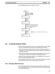
3-8
Creating an I/O Table . . . . . . . . . . . . . . . . . . . . . . . . . . . . . . . . . . . . . . . . . . . . . . . . . . . . . .
49
3-9
Creating Routing Tables . . . . . . . . . . . . . . . . . . . . . . . . . . . . . . . . . . . . . . . . . . . . . . . . . . . .
50
3-10 System Setup. . . . . . . . . . . . . . . . . . . . . . . . . . . . . . . . . . . . . . . . . . . . . . . . . . . . . . . . . . . . .
55
3-11 Checking Communications . . . . . . . . . . . . . . . . . . . . . . . . . . . . . . . . . . . . . . . . . . . . . . . . . .
55
vii
TABLE OF CONTENTS
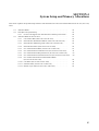
SECTION 4
System Setup and Memory Allocations . . . . . . . . . . . . . . . .
57
4-1
Allocated Words . . . . . . . . . . . . . . . . . . . . . . . . . . . . . . . . . . . . . . . . . . . . . . . . . . . . . . . . . .
58
4-2
CPU Bus Unit System Setup. . . . . . . . . . . . . . . . . . . . . . . . . . . . . . . . . . . . . . . . . . . . . . . . .
59
4-3
Allocated Words in the CIO Area . . . . . . . . . . . . . . . . . . . . . . . . . . . . . . . . . . . . . . . . . . . . .
61
SECTION 5
Data Link. . . . . . . . . . . . . . . . . . . . . . . . . . . . . . . . . . . . . . . . .
67
5-1
Data Link Overview . . . . . . . . . . . . . . . . . . . . . . . . . . . . . . . . . . . . . . . . . . . . . . . . . . . . . . .
68
5-2
Setting Data Link Tables . . . . . . . . . . . . . . . . . . . . . . . . . . . . . . . . . . . . . . . . . . . . . . . . . . . .
72
SECTION 6
Message Transmission . . . . . . . . . . . . . . . . . . . . . . . . . . . . . .
85
6-1
Message Transmission . . . . . . . . . . . . . . . . . . . . . . . . . . . . . . . . . . . . . . . . . . . . . . . . . . . . .
86
6-2
Details of Supported Messages . . . . . . . . . . . . . . . . . . . . . . . . . . . . . . . . . . . . . . . . . . . . . . .
88
SECTION 7
FINS Communications. . . . . . . . . . . . . . . . . . . . . . . . . . . . . .
93
7-1
Overview of FINS Communications. . . . . . . . . . . . . . . . . . . . . . . . . . . . . . . . . . . . . . . . . . .
94
7-2
Sending Commands From a PLC . . . . . . . . . . . . . . . . . . . . . . . . . . . . . . . . . . . . . . . . . . . . .
96
7-3
Command Codes and Response Codes . . . . . . . . . . . . . . . . . . . . . . . . . . . . . . . . . . . . . . . . .
107
7-4
CS-series Memory Areas and Virtual Addresses . . . . . . . . . . . . . . . . . . . . . . . . . . . . . . . . .
108
7-5
Command/Response Reference . . . . . . . . . . . . . . . . . . . . . . . . . . . . . . . . . . . . . . . . . . . . . .
109
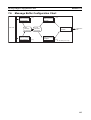
7-6
Message Buffer Configuration Chart . . . . . . . . . . . . . . . . . . . . . . . . . . . . . . . . . . . . . . . . . .
135
SECTION 8
Communications Timing . . . . . . . . . . . . . . . . . . . . . . . . . . . . 137
8-1
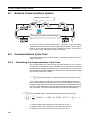
Network Communications System . . . . . . . . . . . . . . . . . . . . . . . . . . . . . . . . . . . . . . . . . . . .
138
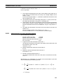
8-2
Communications Cycle Time . . . . . . . . . . . . . . . . . . . . . . . . . . . . . . . . . . . . . . . . . . . . . . . .
138
8-3
Calculating the Data Link I/O Response Time . . . . . . . . . . . . . . . . . . . . . . . . . . . . . . . . . . .
140
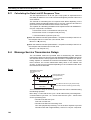
8-4
Message Service Transmission Delays . . . . . . . . . . . . . . . . . . . . . . . . . . . . . . . . . . . . . . . . .
140
SECTION 9
Testing Communications . . . . . . . . . . . . . . . . . . . . . . . . . . . . 143
viii
9-1
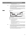
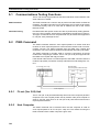
Communications Testing Functions . . . . . . . . . . . . . . . . . . . . . . . . . . . . . . . . . . . . . . . . . . .
144
9-2
PING Command . . . . . . . . . . . . . . . . . . . . . . . . . . . . . . . . . . . . . . . . . . . . . . . . . . . . . . . . . .
144
9-3
Internode Test . . . . . . . . . . . . . . . . . . . . . . . . . . . . . . . . . . . . . . . . . . . . . . . . . . . . . . . . . . . .
145
TABLE OF CONTENTS
SECTION 10
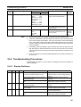
Troubleshooting . . . . . . . . . . . . . . . . . . . . . . . . . . . . . . . . . . . 149
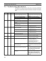
10-1 Troubleshooting with Indicators . . . . . . . . . . . . . . . . . . . . . . . . . . . . . . . . . . . . . . . . . . . . . .
150
10-2 Error Status . . . . . . . . . . . . . . . . . . . . . . . . . . . . . . . . . . . . . . . . . . . . . . . . . . . . . . . . . . . . . .
151
10-3 Error Log. . . . . . . . . . . . . . . . . . . . . . . . . . . . . . . . . . . . . . . . . . . . . . . . . . . . . . . . . . . . . . . .
152
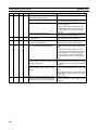
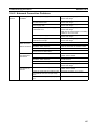
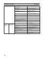
10-4 Troubleshooting Procedures . . . . . . . . . . . . . . . . . . . . . . . . . . . . . . . . . . . . . . . . . . . . . . . . .
155
SECTION 11
FL-net Unit Support Tool . . . . . . . . . . . . . . . . . . . . . . . . . . . 161
11-1 FL-net Unit Support Tool Overview . . . . . . . . . . . . . . . . . . . . . . . . . . . . . . . . . . . . . . . . . . .
162
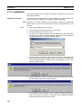
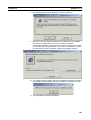
11-2 Installation. . . . . . . . . . . . . . . . . . . . . . . . . . . . . . . . . . . . . . . . . . . . . . . . . . . . . . . . . . . . . . .
164
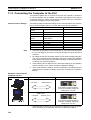
11-3 Connecting the Computer to the PLC . . . . . . . . . . . . . . . . . . . . . . . . . . . . . . . . . . . . . . . . . .
166
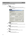
11-4 Using Support Tool Functions . . . . . . . . . . . . . . . . . . . . . . . . . . . . . . . . . . . . . . . . . . . . . . .
168
Revision History . . . . . . . . . . . . . . . . . . . . . . . . . . . . . . . . . . . 187
ix
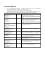
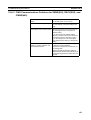
About this Manual:
This manual describes the installation and operation of the SYSMAC CS-series CS1W-FLN02
(10Base-5) and CS1W-FLN12 (10Base-T) FL-net (Ver. 2.00) Units.
FL-net (Ver. 2.00) Units are used to connect to FL-net version-2.0 networks.
Please read this manual and all related manuals listed in the following table carefully and be sure you
understand the information provided before attempting to install and operate an FL-net Unit.
Name
Cat. No.
Contents
SYSMAC CS-series
CS1W-FLN02/FLN12
FL-net Units
Operation Manual
(this manual)
---
Describes the installation and operation of the CS1W-FLN02 (10Base5) and CS1W-FLN12 (10Base-T) FL-net Units.
Refer to the Communications Commands Reference Manual (W342) for
information on FINS commands that can be addressed to CS/CJ-series
CPU Units.
SYSMAC CS/CJ-series
CS1W-ETN01/ETN11
CJ1W-ETN11
Ethernet Units
Operation Manual
W343-E1-@
Describes the installation and operation of the CS1W-ETN01 (10Base5), CS1W-ETN11 (10Base-T), and CJ1W-ETN11 Ethernet Units.
Refer to the CX-Programmer User’s Manual for information on setting
the CPU Bus Unit Setup for the Ethernet Unit.
Refer to the Communications Commands Reference Manual (W342) for
information on FINS commands that can be addressed to CS/CJ-series
CPU Units.
SYSMAC CS/CJ-series
CS1G/H-CPU@@-E,
CJ1G-CPU@@, CS1W-SCB21/41, CS1WSCU21, CJ1W-SCU41 Communications
Commands
Reference Manual
W342-E1-@
Describes the C-series (Host Link) and FINS communications commands used with CS/CJ-series PCs.
SYSMAC CS/CJ-series
CS1G/H-CPU@@-E, CJ1G-CPU@@
Programmable Controllers
Programming Manual
W394-E1-@
Describes programming as well as tasks, file memory, and other functions for CJ-series PCs. Use together with the Operation Manual
(W393).
SYSMAC CS/CJ-series
CS1G/H-CPU@@-E, CJ1G-CPU@@
Programmable Controllers
Instructions Reference Manual
W340-E1-@
Describes the ladder diagram programming instructions supported by
CS-series and CJ-series PCs. Use together with the Operation Manual
(W393) and Programming Manual (W394) to perform programming.
SYSMAC WS02-CXP@@-EV2
CX-Programmer
Operation Manual
W361
Provides information on how to use the CX-Programmer, a Windowsbased programming device, offline. Use together with the Operation
Manual (W393), Programming Manual (W394), and Instructions Reference Manual (W340) to perform programming.
SYSMAC WS02-CXP@@-EV2
CX-Server User Manual
W362
Provides information on how to use the CX-Programmer, a Windowsbased programming device, and CX-Net, a Windows-based network
configuration tool, online.
SYSMAC CS/CJ-series
C200H-PRO27-E, CQM1H-PRO01-E
CQM1-PRO01-E
Programming Consoles
Operation Manual
W341-E1-@
Provides information on how to program and operate CS/CJ-series PCs
using a Programming Console. Use together with the Operation Manual
(W393), Programming Manual (W394), and Instructions Reference
Manual (W340) to perform programming.
SYSMAC CS/CJ-series
CS1W-SCB21/41, CS1W-SCU21
CJ1W-CSU41
Serial Communications Boards and Serial
Communications Units
Operation Manual
W336-E1-@
Describes the use of Serial Communications Units and Boards to perform serial communications with external devices, including the usage
of standard system protocols for OMRON products.
xi
About this Manual, Continued
This manual contains the following sections.
Section 1 introduces the overall structure of an FL-net (Ver. 2.00) network, outlines the features of the
FL-net (Ver. 2.00) Unit, describes the communications protocols used by an FL-net (Ver. 2.00) network, and provides basic precautions for use of the network.
Section 2 describes the communications functions that can be used with the FL-net (Ver. 2.00) Units.
Section 3 explains the procedure for starting up the FL-net (Ver. 2.00) Unit, including mounting to the
PLC, making the required settings, and checking communications.
Section 4 explains the System Setup and the words allocated in the CIO Area and the DM Area for
FL-net (Ver. 2.00) Units.
Section 5 explains the Data Link function, including an overview and examples of how to make the
required settings.
Section 6 describes the message transmission used by an FL-net (Ver. 2.00) network.
Section 7 provides information on communicating on FL-net Systems and interconnected networks
using FINS commands. The information provided in the section deals only with FINS communications
in reference to FL-net (Ver. 2.00) Units.
Section 8 describes the communications system, communications cycle time, communications cycle
time calculation, data link I/O response time, data link I/O response time calculation, and message service transmission delays.
Section 9 describes functions that allow you to test communications.
Section 10 describes information and procedures that can be used to troubleshoot problems that
sometimes occur with FL-net (Ver. 2.00) Unit and FL-net communications.
Section 11 describes the Support Tool used to make settings for the FL-net Units.
!WARNING Failure to read and understand the information provided in this manual may result in personal injury or death, damage to the product, or product failure. Please read each section
in its entirety and be sure you understand the information provided in the section and
related sections before attempting any of the procedures or operations given.
xii
PRECAUTIONS
This section provides general precautions for using the CS/CJ-series Programmable Controllers (PLCs) and related devices.
The information contained in this section is important for the safe and reliable application of Programmable
Controllers. You must read this section and understand the information contained before attempting to set up or
operate a PLC system.
1
2
3
4
5
6
Intended Audience . . . . . . . . . . . . . . . . . . . . . . . . . . . . . . . . . . . . . . . . . . . . .
General Precautions . . . . . . . . . . . . . . . . . . . . . . . . . . . . . . . . . . . . . . . . . . . .
Safety Precautions. . . . . . . . . . . . . . . . . . . . . . . . . . . . . . . . . . . . . . . . . . . . . .
Operating Environment Precautions . . . . . . . . . . . . . . . . . . . . . . . . . . . . . . . .
Application Precautions . . . . . . . . . . . . . . . . . . . . . . . . . . . . . . . . . . . . . . . . .
Conformance to EC Directives . . . . . . . . . . . . . . . . . . . . . . . . . . . . . . . . . . . .
xiv
xiv
xiv
xv
xv
xvii
xiii
1
Intended Audience
1
Intended Audience
This manual is intended for the following personnel, who must also have
knowledge of electrical systems (an electrical engineer or the equivalent).
• Personnel in charge of installing FA systems.
• Personnel in charge of designing FA systems.
• Personnel in charge of managing FA systems and facilities.
2
General Precautions
The user must operate the product according to the performance specifications described in the operation manuals.
Before using the product under conditions which are not described in the
manual or applying the product to nuclear control systems, railroad systems,
aviation systems, vehicles, combustion systems, medical equipment, amusement machines, safety equipment, and other systems, machines, and equipment that may have a serious influence on lives and property if used
improperly, consult your OMRON representative.
Make sure that the ratings and performance characteristics of the product are
sufficient for the systems, machines, and equipment, and be sure to provide
the systems, machines, and equipment with double safety mechanisms.
This manual provides information for programming and operating the Unit. Be
sure to read this manual before attempting to use the Unit and keep this manual close at hand for reference during operation.
!WARNING It is extremely important that a PLC and all PLC Units be used for the specified purpose and under the specified conditions, especially in applications that
can directly or indirectly affect human life. You must consult with your OMRON
representative before applying a PLC System to the above-mentioned applications.
3
Safety Precautions
!WARNING Do not attempt to take any Unit apart while the power is being supplied. Doing
so may result in electric shock.
!WARNING Do not touch any of the terminals or terminal blocks while the power is being
supplied. Doing so may result in electric shock.
!WARNING Do not attempt to disassemble, repair, or modify any Units. Any attempt to do
so may result in malfunction, fire, or electric shock.
!WARNING Do not touch the Power Supply Unit while power is being supplied or immediately after power has been turned OFF. Doing so may result in electric shock.
!Caution Tighten the screws on the terminal block of the AC Power Supply Unit to the
torque specified in the operation manual. The loose screws may result in
burning or malfunction.
xiv
Operating Environment Precautions
4
!Caution Execute online edit only after confirming that no adverse effects will be
caused by extending the cycle time. Otherwise, the input signals may not be
readable.
4
Operating Environment Precautions
!Caution Do not operate the control system in the following places:
• Locations subject to direct sunlight.
• Locations subject to temperatures or humidity outside the range specified
in the specifications.
• Locations subject to condensation as the result of severe changes in temperature.
• Locations subject to corrosive or flammable gases.
• Locations subject to dust (especially iron dust) or salts.
• Locations subject to exposure to water, oil, or chemicals.
• Locations subject to shock or vibration.
!Caution Take appropriate and sufficient countermeasures when installing systems in
the following locations:
• Locations subject to static electricity or other forms of noise.
• Locations subject to strong electromagnetic fields.
• Locations subject to possible exposure to radioactivity.
• Locations close to power supplies.
!Caution The operating environment of the PLC System can have a large effect on the
longevity and reliability of the system. Improper operating environments can
lead to malfunction, failure, and other unforeseeable problems with the PLC
System. Be sure that the operating environment is within the specified conditions at installation and remains within the specified conditions during the life
of the system. Follow all installation instructions and precautions provided in
the operation manuals.
5
Application Precautions
Observe the following precautions when using the PLC System.
!WARNING Always heed these precautions. Failure to abide by the following precautions
could lead to serious or possibly fatal injury.
• Always connect to a ground of 100 Ω or less when installing the Units. Not
connecting to a ground to a ground of 100 Ω or less may result in electric
shock.
• A ground of 100 Ω or less must be installed when shorting the GR and LG
terminals on the Power Supply Unit.
• Always turn OFF the power supply to the PLC before attempting any of
the following. Not turning OFF the power supply may result in malfunction
or electric shock.
xv
5
Application Precautions
• Mounting or dismounting I/O Units, CPU Units, Inner Boards, or any
other Units.
• Assembling the Units.
• Setting DIP switches or rotary switches.
• Connecting cables or wiring the system.
!Caution Failure to abide by the following precautions could lead to faulty operation of
the PLC or the system, or could damage the PLC or PLC Units. Always heed
these precautions.
• Fail-safe measures must be taken by the customer to ensure safety in the
event of incorrect, missing, or abnormal signals caused by broken signal
lines, momentary power interruptions, or other causes.
• Interlock circuits, limit circuits, and similar safety measures in external circuits (i.e., not in the Programmable Controller) must be provided by the
customer.
• Always use the power supply voltages specified in the operation manuals.
An incorrect voltage may result in malfunction or burning.
• Take appropriate measures to ensure that the specified power with the
rated voltage and frequency is supplied. Be particularly careful in places
where the power supply is unstable. An incorrect power supply may result
in malfunction.
• Install external breakers and take other safety measures against short-circuiting in external wiring. Insufficient safety measures against short-circuiting may result in burning.
• Be sure that all the mounting screws, terminal screws, and cable connector screws are tightened to the torque specified in the relevant manuals.
Incorrect tightening torque may result in malfunction.
• Leave the label attached to the Unit when wiring. Removing the label may
result in malfunction if foreign matter enters the Unit.
• Remove the label after the completion of wiring to ensure proper heat dissipation. Leaving the label attached may result in malfunction.
• Use crimp terminals for wiring. Do not connect bare stranded wires
directly to terminals. Connection of bare stranded wires may result in
burning.
• Wire all connections correctly.
• Double-check all wiring and switch settings before turning ON the power
supply. Incorrect wiring may result in burning.
• Mount Units only after checking terminal blocks and connectors completely.
• Be sure that the terminal blocks, Memory Units, expansion cables, and
other items with locking devices are properly locked into place. Improper
locking may result in malfunction.
• Check the user program for proper execution before actually running it on
the Unit. Not checking the program may result in an unexpected operation.
• Do not lay communications cables near power lines or high-voltage lines.
• Always lay communications cables in ducts.
xvi
6
Conformance to EC Directives
• Do not pull on the communications cables or bend the communications
cables beyond their natural limit. Doing either of these may break the
cables.
• Do not place objects on top of the communications cables or other wiring
lines. Doing so may break the cables.
• Before touching a Unit, be sure to first touch a grounded metallic object in
order to discharge any static built-up. Not doing so may result in malfunction or damage.
• When transporting or storing Units, place them in special packing boxes
and do not allow them to be subject to excessive shock or vibration during
transportation.
• Confirm that no adverse effect will occur in the system before attempting
any of the following. Not doing so may result in an unexpected operation.
• Changing the operating mode of the PLC.
• Force-setting/force-resetting any bit in memory.
• Changing the present value of any word or any set value in memory.
6
6-1
Conformance to EC Directives
Applicable Directives
• EMC Directives
• Low Voltage Directive
6-2
Concepts
EMC Directives
OMRON devices that comply with EC Directives also conform to the related
EMC standards so that they can be more easily built into other devices or the
overall machine. The actual products have been checked for conformity to
EMC standards (see the following note). Whether the products conform to the
standards in the system used by the customer, however, must be checked by
the customer.
EMC-related performance of the OMRON devices that comply with EC Directives will vary depending on the configuration, wiring, and other conditions of
the equipment or control panel on which the OMRON devices are installed.
The customer must, therefore, perform the final check to confirm that devices
and the overall machine conform to EMC standards.
Note Conformance with the EMC (Electromagnetic Compatibility) standards for
EMS (Electromagnetic Susceptibility) and EMI (Electromagnetic Interference)
vary with the model in the way shown below.
FL-net (Ver. 2.00) Unit
CS1W-FLN02/12
EMS
EN61131-2
EMI
EN50081-2 (Radiated
emission: 10-m regulations)
Low Voltage Directive
Always ensure that devices operating at voltages of 50 to 1,000 VAC and 75
to 1,500 VDC meet the required safety standards for the PLC (EN61131-2).
xvii
SECTION 1
Features and System Configuration
This section introduces the overall structure of an FL-net (Ver. 2.00) network, outlines the features of the FL-net (Ver. 2.00)
Unit, describes the communications protocols used by an FL-net (Ver. 2.00) network, and provides basic precautions for
use of the network.
1-1
1-2
FL-net Overview . . . . . . . . . . . . . . . . . . . . . . . . . . . . . . . . . . . . . . . . . . . . . . .
2
System Configuration . . . . . . . . . . . . . . . . . . . . . . . . . . . . . . . . . . . . . . . . . . .
6
1-2-1
Device Configuration . . . . . . . . . . . . . . . . . . . . . . . . . . . . . . . . . . . .
6
1-2-2
Node Connections. . . . . . . . . . . . . . . . . . . . . . . . . . . . . . . . . . . . . . .
7
Devices Required in a Network . . . . . . . . . . . . . . . . . . . . . . . . . . . . . . . . . . .
7
1-3-1
10Base-5 FL-net (Ver. 2.00) Systems . . . . . . . . . . . . . . . . . . . . . . . .
7
1-3-2
10Base-T FL-net (Ver. 2.00) Systems. . . . . . . . . . . . . . . . . . . . . . . .
9
1-4
Related Programming Devices . . . . . . . . . . . . . . . . . . . . . . . . . . . . . . . . . . . .
10
1-5
Specifications . . . . . . . . . . . . . . . . . . . . . . . . . . . . . . . . . . . . . . . . . . . . . . . . .
11
1-3
1-6
Precautions . . . . . . . . . . . . . . . . . . . . . . . . . . . . . . . . . . . . . . . . . . . . . . . . . . .
13
1-6-1
Installation . . . . . . . . . . . . . . . . . . . . . . . . . . . . . . . . . . . . . . . . . . . .
13
1-6-2
Ethernet and IEEE802.3 Standards. . . . . . . . . . . . . . . . . . . . . . . . . .
13
1
Section 1-1
FL-net Overview
1-1
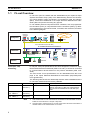
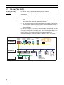
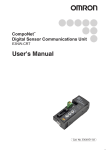
FL-net Overview
FL-net is an open FA network that was standardized by the Japan FA Open
Systems Promotion Group (JOP) of the Manufacturing Science and Technology Center (MSTC) under the Ministry of International Trade and Industry
(MITI). It has been established in the Japan Electrical Manufacturers standards (JEM 1479) and is becoming very popular.
FL-net enables personal computers and FA controllers, such as programmable controllers (PLCs) or computerized numeric controllers (CNCs), by different manufacturers to be interconnected, controlled, and monitored, as shown
in the following diagram.
Personal
computer
EWS
Server
Computers
WAN
Host LAN Ethernet (TCP/IP, UDP)
FL-net Ethernet-based Control Network
PLC
PLC
PLC
Controllers
Personal
computer
CNC
RC
Field Network
Sensors
Devices
Actuators
FL-net (Ver. 2.00)
Positioning
FL-net (Ver. 2.00) Unit specifications have been designed to conform to Japan
Electrical Manufacturers standards (JEM 1479: 2001). It cannot be connected
to communications devices based on the previous standards (JEM 1479:
2000).
The most recent FL-net specifications can be downloaded from the home
page of the Japan Electrical Manufacturers Association (http://www.jemanet.or.jp/index.htm).
The following table shows the relationship between these standards and the
FL-net Units manufactured and sold by OMRON.
Unit name
Model
Applicable standards
Manufacture and sales
FL-net Unit
CS1W-FLN01
(See note 1.)
JEM 1479: 2000
FL-net (Ver. 2.00)
Unit, 10Base-5
FL-net (Ver. 2.00)
Unit, 10Base-T
CS1W-FLN02
(See note 2.)
CS1W-FLN12
(See note 2.)
JEM 1479: 2001
Under the guidance of the JEMA, communications
devices conforming to JEM 1479: 2000 specifications cannot be manufactured or sold after April,
2001.
Planned to be available from April, 2001, onwards.
JEM 1479: 2001
Planned to be available from April, 2001, onwards.
Note
1. The CS1W-FLN01 FL-net Unit cannot be connected to a network based on CS1WFLN02 or CS1W-FLN12 FL-net (Ver. 2.00) Units.
2. CS1W-FLN02 or CS1W-FLN12 FL-net (Ver. 2.00) Units cannot be connected to a
network based on the CS1W-FLN01 FL-net Unit.
2
Section 1-1
FL-net Overview
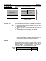
FL-net Features
FL-net systems have the following features.
1. FL-net is an open system.
2. FL-net enables a multi-vendor network.
3. FL-net enables personal computers and FA controllers, such as programmable controllers (PLCs) or computerized numeric controllers (CNCs), by
different manufacturers to be interconnected, controlled, and monitored.
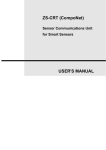
Application layer
FA link protocol layer
User application Interface
Cyclic transmission
Message service
Message
transmission
Token management
Transport layer
UDP
Network layer
IP
Data link layer
Ethernet
(IEEE802.3 standard)
Physical layer
FL-net
protocol
Figure 1 Basic Configuration of FL-net Protocol
Conforms to Widely Used Standards
Efficient communications can be achieved by this system based on Ethernet,
which has become the standard particularly for OA devices, combined with
standard UDP/IP. The use of Ethernet offers the following benefits.
1. Low cost
Configurations allowing the application of widely used communications devices reduces costs.
2. Compatible with existing network devices
Transceivers, hubs, cables, LAN cards for personal computers, and other
network devices widely used for Ethernet can be used.
3. Higher speeds
Baud rates are expected to improve in the future, increasing to 10 Mbps,
100 Mbps, and 1 Gbps.
4. Optical communications
By using devices such as optical repeaters, which are widely used with
Ethernet, optic fiber can be used for necessary components to enable
long-distance transmission of over 500 m, improved noise resistance, and
measures against lightning surge on outdoor wiring.
3
Section 1-1
FL-net Overview
Supports Required Functions between FA Controllers
User-defined specifications allow the following range of features that are
required for FA systems.
1. Large-scale network
Up to 254 devices (nodes) can be connected in the physical layer of the
network.
2. Dual communications functions to suit application
The Common Memory function uses cyclic transmission so that each node
can always share the same data with other nodes on the network. FL-net
also supports message communications for use when handling only essential data is required.
3. Large-capacity Common Memory
The Common Memory is provided with a large capacity of 8 Kbits and 8
Kwords.
4. High-speed response
High-speed response time of 50 ms/32 nodes (for 2 Kbits and 2 Kwords)
is provided.
The absence of a master in the FL-net network enables nodes to be added
or removed readily without affecting any other nodes. This allows any node
to be turned ON or OFF easily and facilitates maintenance.
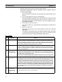
FL-net FAQ
4
Question
Answer
1
What is Ethernet?
Ethernet is a standard defining a type of cable. It is used in a local area network (LAN).
An Ethernet network transmits data between computers at a baud rate of between 10
Mbps and 100 Mbps. Currently, the most commonly used Ethernet in offices and other
OA systems is twisted-pair cable (UTP) that uses 10 Mbps. Ethernet communications are
possible using software protocols provided by many vendors.
2
What is FL-net?
The FL-net is a network to which programmable controllers (PLCs), computerized
numeric controllers (CNCs), and other FA controllers are connected, and on which control data is exchanged between controllers at high speed. FL-net uses the same cables
that are used for Ethernet.
3
What is the difference between FLnet and Ethernet?
With Ethernet, the host computer, personal computers, and controllers are connected to
the network for data exchange and control applications, such as executing production
instructions and compiling results. The FL-net is used to connect controllers together and
allow high-speed control data exchange.
Be sure to connect cables properly when installing both Ethernet for communications with
the host and FL-net for communications between controllers for the same controllers.
4
How are FL-net
Units used?
FL-net Units are installed in FA controllers, such as programmable controllers (PLCs) and
computerized numeric controllers (CNCs). By simply setting link allocations for the local
node address (node number) and Common Memory (also called link registers), FL-net
Units transmit data between controllers cyclically in the same way as CPU Link Units in
standard PLCs. This method does not require special communications programs for the
PLC and other Units on the network. Such programs are also not required by the PLC for
operations conducted via the personal computer, including reading or writing data, such
as the PLC memory or communications parameters. Separate programs are required for
each controller, however, when transmitting data between controllers using message
communications.
5
What does “protocol” mean and
what protocols
does FL-net support?
Protocol refers to rules for communications. The protocols supported by FL-net are UDP/
IP and FA Link Protocol. (The FA Link Protocol is located in the layer above UDP/IP and
is a special protocol for use on FL-net networks.)
Section 1-1
FL-net Overview
Question
Answer
6
Can FL-net be
connected to a
standard personal
computer?
The FL-net Unit, which is mounted to FA controllers such as programmable controllers
(PLCs) and computerized numeric controllers (CNCs), is an intelligent unit with a processor on its board. The Ethernet Card in the personal computer is a non-intelligent format
called a “dumb board,” so its capacity depends on the performance and functions of the
personal computer. Generally, an intelligent FL-net board is recommended.
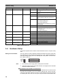
7
What does “topology” mean?
Networking topology refers to the wiring formation of the network. The three main formations are star (or tree), bus, and ring. Rather than physical wiring formations, however, it
is easier to understand them as theoretical formations. An FL-net system has star topology when using 10Base-T cables and bus topology when using 10Base-5 cables.
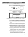
8
What type and
length of network
cables are used,
and how many
Units can be connected?
The most commonly used Ethernet cable standards and some of their characteristics and
limitations are listed below. The figures in parentheses are applicable when repeaters are
used.
• 10Base-T: Twisted-pair cables (UTP), maximum transmission distance is 100 m
(500 m) per segment, maximum number of Units is 254 per segment.
• 10Base-5: Thick coaxial cables (yellow cables), maximum transmission distance is
500 m (2,500 m) per segment, and maximum number of Units that can be connected
is 100 (254) per segment.
• 10Base-FL: Optic fiber cable, maximum transmission distance is 2,000 m per segment, and maximum number of Units that can be connected is 254 per segment.
9
Do systems using
FL-net require
special Ethernet
specifications?
No. FL-net systems are configured using Ethernet (conforming to the IEEE802.3 standard). Special specifications are not required.
10
How do you connect to FL-net?
Ethernet cables for different types of Ethernet media can be connected to each other
using repeaters, media adapters, and other devices. These products are available from
many vendors.
11
What type of
cables should be
used when configuring an FL-net
system?
In general, use the following cables.
• Basic wiring: 10Base-5 Thick coaxial cables; yellow cables.
• In the control panel and in offices: 10Base-T twisted-pair cables; UTP category 5.
• High-voltage wiring and noise-prone environments: 10Base-FL optic-fiber cables.
12
How is the FL-net
IP address set?
The FL-net IP address is set as follows:
Network address: 192.168.250
Host number (node number): 1 to 254 is standard. Nodes 250 to 254, however, are
reserved for maintenance devices.
13
How compatible
and inter-connectable are devices
that support FLnet?
FL-net has a certification system whereby compatibility and inter-connectivity tests are
performed.
Certification documents are provided for those devices that pass the tests, so devices
supporting FL-net can be used safely on the network.
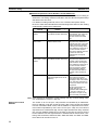
OMRON FL-net (Ver. 2.00) Unit Features
FINS Message
Communications
The FL-net (Ver. 2.00) Unit also supports FINS message communications,
OMRON’s standard communications service, so other OMRON PLCs can be
accessed by using SEND(090), RECV(098), and CMND(490) instructions in
ladder programs. In addition, the FINS gateway function can be used to allow
access to other PLCs on not only the same FL-net (Ver. 2.00) network but
also on other networks such as Ethernet or Controller Link.
24-VDC Power Supply for
Transceiver
For the CS1W-FLN02 (10Base-5), a 24-VDC power supply can be used as
the power supply for the transceiver. The voltage output provides for a voltage
5
Section 1-2
System Configuration
drop in the transceiver cables, so there is no need to adjust the power supply
voltage.
Controller Link Network
Connection
Ethernet, the information-system network, can be connected to Controller
Link, the control-system network, using the FINS communications service.
This allows a PLC on the Ethernet or Controller Link network to be monitored
from an OMRON PLC on the FL-net (Ver. 2.00) network, and, conversely, for
data to be exchanged between a PLC on the Ethernet or Controller Link network and an OMRON PLC on the FL-net (Ver. 2.00) network.
Abundant
Troubleshooting
Functions
The Ethernet Unit is provided with a variety of troubleshooting functions for
prompt recovery in case of errors.
• Self-diagnostic function at startup
• PING command for checking other nodes
• Inter-nodal tests for checking other nodes
• Error log for recording error history data
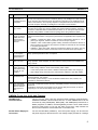
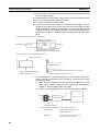
1-2
System Configuration
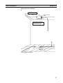
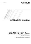
1-2-1
Device Configuration
CX-Programmer
Terminator
Ethernet (10 Mbps)
500 m/segment max.
10Base-5 coaxial cable
(or 10Base-T twisted-pair cable)
CS-series
CS1W-FLN02
FL-net (Ver. 2.00) Unit
(10Base-5)
Terminator
Transceiver
Transceiver cable
CS-series
CS1W-FLN02
FL-net (Ver. 2.00) Unit
(10Base-5)
CS-series
PC
Ground
CS-series PC
CS-series
CS1W-ETN01
Ethernet Unit
(10Base-5)
FL-net (Ver. 2.00) (10 Mbps)
500 m/segment max.
10Base-5 coaxial cable
(or 10Base-T twisted-pair cable)
Between nodes:
Integral multiples of 2.5 m
50 m max.
Terminator
Other company’s
FL-net node
10Base-T
Terminator
Ground
Hub
100 m max.
CS-series
CS1W-FLN12
FL-net (Ver. 2.00) Unit
(10Base-T)
Other company’s
FL-net node
10Base-T
CS-series
PC
DeviceNet
CS-series DeviceNet Unit
Remote Terminal
Note
Sensor
Actuator
1. Transmission distance (from Terminator to Terminator):
500 meters/segment max.
2. When segments are indirectly connected by a repeater: 2.5 km/network
3. Node interval (from transceiver to transceiver): Integral multiples of 2.5 m
4. Transceiver cable length: 50 m max.
6
Section 1-3
Devices Required in a Network
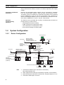
1-2-2
Node Connections
Minimal Configuration: 1 Segment
10Base-5
Node
10Base-T
Node
Node
Node
Node
1 segment
Hub
Configuration With
Segment Extension
Use repeaters to extend the distance between nodes or to increase the number of connected nodes.
10Base-5
Node
1-3
Repeater
Node
Node
Node
Devices Required in a Network
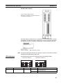
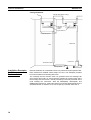
1-3-1
10Base-5 FL-net (Ver. 2.00) Systems
The basic configuration of a 10Base-5 FL-net (Ver. 2.00) System consists of a
single coaxial cable together with the transceivers, transceiver cables, nodes,
and so on, that are connected to it. This basic configuration is called a “segment.”
CS1W-FLN02 FL-net (Ver. 2.00) Unit
24-VDC
power supply
50 m max.
Terminator
(terminating resistance)
Transceiver cable (AUI cable)
Transceivers
Coaxial cable (10Base-5, outer diameter approx. 10 mm)
2.5 m min.
(multiple of 2.5 m)
Terminator (terminating resistance)
Segment (500 m max.)
Number of branch points: 100
The devices shown in the following table must be obtained to configure a network using a 10Base-5 CS1WFLN02 FL-net (Ver. 2.00) Unit, so prepare them
7
Section 1-3
Devices Required in a Network
in advance. Use only devices in the network that conform to IEEE802.3 standards.
Network device
Contents
CS-series FL-net (Ver. 2.00) The 10Base-5 FL-net (Ver. 2.00) Unit is a
Unit (CS1W-FLN02)
Communications Unit that connects a CS-series PLC
to a 10Base-5 FL-net (Ver. 2.00) network.
24-VDC power supply
This is a external 24-VDC power supply for the
purpose of providing power to the transceivers via
transceiver cable. Use a power supply with an output
current of at least 0.3 A per node. The power is
converted within the Unit to the transceiver power
supply voltage, and is provided to the transceiver.
Transceiver
The transceiver is a device for interfacing between the
coaxial cable and the nodes.
Note: The FL-net (Ver. 2.00) Unit can provide a
maximum current of 0.4 A to the transceiver, so use a
transceiver with a current consumption of not more
than 0.4 A. Check with the manufacturer for
information regarding transceiver current
consumption.
Transceiver cable (AUI
This is the cable for connecting between transceivers
cable)
and nodes.
Coaxial cable
The coaxial cable comprises the main line of the FLnet (Ver. 2.00) System.
Terminator for coaxial cable
(terminating resistance)
Note
The Terminators connect to both ends of the coaxial
cable.
1. It is also possible to use 10Base-T twisted-pair cable by connecting the FLnet (Ver. 2.00) Unit to a 10Base-T conversion adapter.
2. A 24-VDC power supply is required even if a 10Base-T conversion adapter
is used.
10Base-T conversion adapter
Recommended
Transceivers, Cables,
and Power Supply
The following table shows the recommended transceivers, transceiver cable
(AUI cable), and 24-V DC power supply.
Device
Transceiver
Transceiver cable
Power supply 24 V
DC)
Maker
Hirakawa Hewtech Corp.
Mitsubishi Cable Industries,
Ltd.
Mitsubishi Cable Industries,
Ltd.
OMRON
Model
MTX-210TZ
ET-10081
Transceiver cable (molded
type)
S82J Series
The products recommended here have been checked for use with the FL-net
(Ver. 2.00) Unit. The operating environment must conform to the individual
product specifications.
8
Section 1-3
Devices Required in a Network
1-3-2
10Base-T FL-net (Ver. 2.00) Systems
The basic configuration of a 10Base-T FL-net (Ver. 2.00) System consists of
one hub to which nodes are attached in star form through twisted-pair cable.
CS1W-FLN12 FL-net (Ver. 2.00) Unit
Twisted-pair cables
100 m max.
100 m max.
Hub
The devices shown in the following table must be obtained to configure a network using a 10Base-T FL-net (Ver. 2.00) Unit, so prepare them in advance.
Network device
Contents
CS-series FL-net (Ver.
2.00) Unit (CS1WFLN12)
Twisted-pair cable
The 10Base-T FL-net (Ver. 2.00) Units are
Communications Units that connect CS-series PLCs to FLnet (Ver. 2.00) networks.
A twisted-pair cable that connects the 10Base-T FL-net
(Ver. 2.00) Unit to the hub. The twisted-pair cable must
have an RJ45 Modular Connector attached to each end.
Use a category 3, 4, or 5 UTP (unshielded twisted-pair)
cable.
Hub
A relay devices that connect multiple nodes in as star LAN.
Recommended Hub
Manufacturer
Allied Telesis
Model number
RH509E
MR820TLX
Specifications
9-port hub
9-port hub with 10Base-5 backbone port
9
Section 1-4
Related Programming Devices
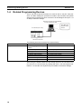
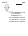
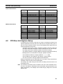
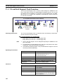
1-4
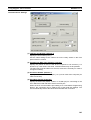
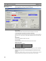
Related Programming Devices
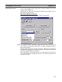
The FL-net (Ver. 2.00) Unit functions as a node on the FL-net (Ver. 2.00) network. The basic settings for operation are made in the CPU Bus Unit System
Setup in the CS-series CPU Unit. Use the FL-net Unit Support Tool (Ver. 1.51
or later) to make the settings.
Personal computer running Windows
FL-net Unit Support Tool
CPU Bus Unit
System Setup
Screen
FL-net Unit (Ver. 2.00)
CS-series CPU Unit
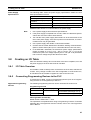
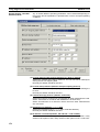
The following items are included in the System Setup.
Screen
Setup Screen
Item
FA Link mapping table storage
method
FA Link startup method
Default
PLC built-in method
Automatic participation method
Message protocol check
Broadcast setting
Yes
***.***.***.255
IP address setting method
Subnetwork mask
192.168.250.node number
255.155.155.0
Local node setting area
Other node setting area
Not set.
Not set.
When using the default values that are already stored in the CS-series CPU
Unit, there is no need to make any settings with the FL-net Unit Support Tool.
Refer to 4-2 CPU Bus Unit System Setup for details on the above settings.
10
Section 1-5
Specifications
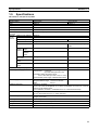
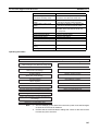
1-5
Specifications
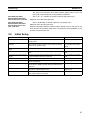
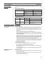
CS-series FL-net (Ver. 2.00) Units
Item
Specifications
Model number
CS1W-FLN02
CS1W-FLN12
Type
Applicable PLCs
10Base-5
CS-series PLCs
10Base-T
Unit classification
Mounting location
CS-series CPU Bus Unit
CPU Rack or Expansion Rack
Number of Units that can be
mounted
4 max. (including Expansion Racks)
Transfer
specifications
Media access method
Modulation
CSMA/CD
Baseband
Transmission paths
Baud rate
Bus
10 Mbps
Star
Transmission media
Coaxial cable
Unshielded twisted-pair (UTP)
cable
TransSegment
mission length
distance Distance
between
nodes
500 m max.
100 m max.
2,500 m max.
---
Number of connectable nodes
100/segment max.
---
Multiples of 2.5 m
---
50 m max.
---
400 mA max. at 5 VDC
400 mA max. at 5 VDC
External power supply
Capacity:
Inrush current:
---
Power supply to transceiver
--Capacity:
0.4 A at 12 V
Voltage fluctuation range: 13.05 to 14.48 VDC
Ripple:
2% p-p
Conforms to JIS 0040.
10 to 57 Hz, 0.075-mm amplitude, 57 to 150 Hz, acceleration: 9.8 m/s2 in X, Y, and Z
directions for 80 minutes each
(Time coefficient; 8 minutes × coefficient factor 10 = total time 80 minutes)
Distance between
nodes
Transceiver cable
length
Current consumption (Unit)
Vibration resistance
Shock resistance
0.3 A min. at 24 VDC (per node)
2.5 A max.
(24-VDC startup time of 5 ms)
Permissible voltage fluctuation range:
20.4 to 26.4 VDC (24 VDC –15% to +10%)
Recommended power supply: OMRON S82J-series
Humidity
Conforms to JIS 0041.
147 m/s2 three times each in X, Y, and Z directions
Operating: 0 to 55°C
Storage: –20 to 75°C
10% to 90% (with no condensation)
Atmosphere
Weight
Must be free from corrosive gas.
300 g max.
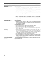
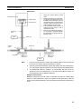
Dimensions
35 x 130 x 101 mm (W x H x D)
Ambient temperature
11
Section 1-5
Specifications
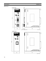
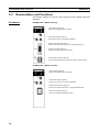
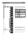
Dimensions
CS1W-FLN02
FLN02
(16.5 including cover)
(Unit: mm)
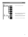
CS1W-FLN12
FLN12
(Unit: mm)
12
Section 1-6
Precautions
1-6
Precautions
Be sure to observe the following precautions when installing and using an FLnet (Ver. 2.00) Unit.
1-6-1
Installation
Observe the following precautions when installing an FL-net (Ver. 2.00) Unit.
1,2,3...
1. Use transceiver cable that meets IEEE802.3 standards to ensure high
noise resistance.
2. Use a transceiver with a current consumption of not more than 0.4 A per
port.
3. Always turn off the power supply to the PLC before connecting or disconnecting the transceiver cable.
4. Be sure not to exceed the current capacity of the Power Supply Unit on the
Rack to which the FL-net (Ver. 2.00) Unit is mounted. The current consumption of the CS-series FL-net (Ver. 2.00) Unit is 400 mA maximum.
This value added to the current consumption of all other Units mounted to
the same Rack must not exceed the capacity of the Power Supply Unit.
5. Do not install the transceiver cables or coaxial cables of the network near
power supply lines. If installation near possible sources of noise is unavoidable, install the cables in grounded metal ducts or take other measure to
eliminate noise interference.
1-6-2
Ethernet and IEEE802.3 Standards
The FL-net (Ver. 2.00) Unit was designed based on Version-2.0 Ethernet standards and not on the international IEEE802.3 standards, which were developed based on Ethernet specifications. Although these two sets of standards
are similar, they are not necessarily the same. Particularly, different frame formats are used, making direct communications impossible between systems
that do not support the same standards. Standards for equipment used to
configure networks are the same, allowing IEEE802.3-standard equipment to
be used with the FL-net (Ver. 2.00) Unit. In particular, the transceiver cable for
the IEEE802.3 standards provides superior noise resistance and should be
used for the FL-net (Ver. 2.00) Unit.
Terminology also differs between Version-2.0 Ethernet and IEEE802.3 standards. These differences are shown in the following table. Version-2.0 Ethernet terminology is used in this manual.
Ethernet
IEEE802.3
Transceiver
Transceiver cable
MAU
AUI
Ethernet address
Ethernet
MAC address
10Base-5/10Base-T
13
SECTION 2
Communications Functions
This section describes the communications functions that can be used with the FL-net (Ver. 2.00) Units.
2-1
FL-net (Ver. 2.00) . . . . . . . . . . . . . . . . . . . . . . . . . . . . . . . . . . . . . . . . . . . . . .
16
2-2
Cyclic Transmission . . . . . . . . . . . . . . . . . . . . . . . . . . . . . . . . . . . . . . . . . . . .
21
2-3
Message Transmission . . . . . . . . . . . . . . . . . . . . . . . . . . . . . . . . . . . . . . . . . .
22
2-4
FINS Communications Service. . . . . . . . . . . . . . . . . . . . . . . . . . . . . . . . . . . .
22
15
Section 2-1
FL-net (Ver. 2.00)
2-1
FL-net (Ver. 2.00)
FL-net (Ver. 2.00)
Concept
FL-net (Ver. 2.00) is an Ethernet-based FA control network.
FL-net (Ver. 2.00) supports both cyclic transmission and message transmission functions.
The basic concepts of FL-net (Ver. 2.00) are as follows:
1,2,3...
1. To use Ethernet as the medium for communications between FA controllers.
2. To offer UDP/IP, which are widely used protocols in Ethernet communications, as the basic means for data communications.
3. To manage and control access of each node in the network to the communications media (to avoid collisions) and to ensure transmission within a
fixed time period, while using the above-mentioned basic means for data
communications.
FL-net (Ver. 2.00) is an FA control network enabling the exchange of data
between control devices in manufacturing systems, such as programmable
controllers (PLCs), robot controllers (RCs), and computerized numeric controllers (CNCs), and personal computers used for controlling them.
The following diagram shows the location of devices in an FL-net system.
Personal
computer
Personal
computer
Personal
computer
Server
EWS
Computers
WAN
Host LAN Ethernet (TCP/IP, UDP)
FL-net Ethernet-based Control Network
PLC
PLC
PLC
Controllers
Personal
computer
DeviceNet or other network
Sensors
Devices
16
Actuators
OMRON FL-net
Unit Support Tool
CNC
RC
Section 2-1
FL-net (Ver. 2.00)
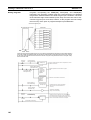
FL-net (Ver. 2.00)
Protocol
FL-net (Ver. 2.00) consists of six protocol layers, as shown in the following diagram.
Application layer
User application Interface
Message service
Cyclic transmission
Message transmission
FA link protocol layer
Token management
Transport layer
UDP
Network layer
IP
Data link layer
Ethernet
(IEEE802.3 standard)
FL-net
Protocol
Note The transport and network layers use UDP/IP, whereas Ethernet is used as
the protocol for the data link and physical layers.
FL-net (Ver. 2.00)
Transmission Features
1,2,3...
FL-net (Ver. 2.00)'s FA link protocol layer is characterized by the following features.
1. Collisions are avoided by transmission control that uses the token method
that does not use a master.
2. The refresh cycle time can be regulated by fixing the cycle time of the token.
3. The designated token is transmitted together with cyclic data.
4. The token is transmitted first by the node that has the smallest number at
startup.
5. When no token is transmitted in a specified period of time, the next node
in the token rotation order sends a new token.
6. This token method prevents the network from stopping when there is a failure of only some of the nodes.
7. The information management tables provide useful information, such as
operation mode (RUN/STOP) and hardware malfunctions (ALARM), that
can be referenced to monitor the operating status of other nodes.
FL-net (Ver. 2.00) IP
Addresses
Unique class-C IP addresses must be assigned to each node in the FL-net
(Ver. 2.00) network.
An IP address is an address identifying each node (station) for transmission
using IP (internet protocol). Therefore, IP addresses must be set and managed so that no two nodes have the same IP address. FL-net (Ver. 2.00) uses
Class-C IP addresses. The default IP address for FL-net (Ver. 2.00) is
192.168.250.***, with *** representing the remote node number.
FL-net (Ver.
2.00) IP
address
Network address
Host number
(node number)
192.168.250
n (n: 1 to 254)
17
Section 2-1
FL-net (Ver. 2.00)
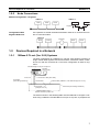
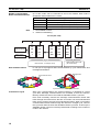
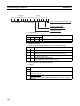
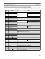
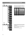
Number of Connectable
Nodes and Node Numbers
Up to 254 nodes can be connected to an FL-net network. Each node is
assigned a node number from 1 to 254.
Note
Node number
1 to 249
Applications
Used for standard FL-net (Ver. 2.00) devices.
250 to 254
255
Used for FL-net (Ver. 2.00) maintenance purposes.
Reserved for internal system use. (See notes 1 and 2.)
0
Reserved for internal system use. (See note 1.)
1. Not available to users.
2. Used for broadcasting.
FL-net (Ver. 2.00)
Network address
Node number
192.
192.
192.
192.
192.
192.
168.
168.
168.
168.
168.
168.
250.
250.
250.
250.
250.
250.
1
2
248
249
250
254
Node number: 1 to 249 (for users)
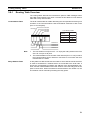
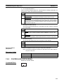
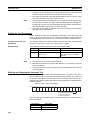
Data Communications
FL-net (Ver. 2.00) supports data communications by cyclic transmission and
message transmission.
Cyclic data with token
Cyclic transmission
Transmission Cycle
Node number: 250 to 254
(for maintenance)
Message data
Cyclic transmission + message transmission
With cyclic communications, the Common Memory is refreshed on a fixed
cycle time. Message communications are controlled so that the Common
Memory refresh time does not exceed the allowable refresh cycle time.
Each node constantly monitors the message communications frames that
travel through the network from the time it receives one local-node-directed
token until it receives the next local-node-directed token. When no message
communications frame travels through the network in a single cycle, 120% of
the cycle time value becomes the allowable refresh cycle time. In this way the
allowable refresh cycle time is actively determined according to the number of
nodes in the network.
18
Section 2-1
FL-net (Ver. 2.00)
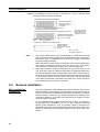
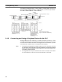
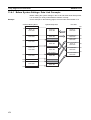
Data Areas and Memory
FL-net (Ver. 2.00)
FL-net Communications Unit
CPU Unit
Message transmission
Cyclic transmission
Common Memory Area 1
Common Memory Area 2
Message transmission buffer area
FL-net management table area
Physical memory
FL-net parameter area
Communications
Management Tables
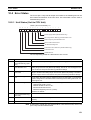
Node status is managed using three types of management tables: Local node
management tables, participating node management tables, and network
management
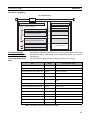
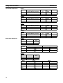
Local Node Management
Table
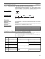
The local node management table manages the local node settings.
Item
Bytes
Contents (data range)
Node number
1 byte
1 to 249
Common Memory Area 1 first word
2 bytes
Word address (0 to 0xff)
Common Memory Area 1 data size
2 bytes
Size (0 to 0x200)
Common Memory Area 2 first word
2 bytes
Word address (0 to 0x2000)
Common Memory Area 2 data size
2 bytes
Size (0 to 0x200)
Upper layer status
2 bytes
RUN/STOP /ALARM/WARNING/NORMAL
Token monitoring time
1 byte
Unit: 1 ms
Minimum allowable frame interval
1 byte
Unit: 100 µs
Vendor code
10 bytes
Vendor code
Manufacturer model
10 bytes
Manufacturer model, device name
Node name (equipment name)
10 bytes
User-defined node name
Protocol version
1 byte
0x80 (fixed)
FA link status
1 byte
Participating, not participating, etc.
Local node status
1 byte
Duplicate node number detection, etc.
Note “0x0012ab” refers to hexadecimal 0012AB.
19
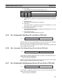
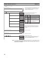
FL-net (Ver. 2.00)
Section 2-1
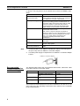
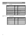
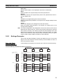
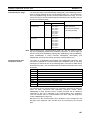
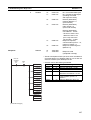
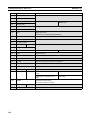
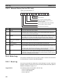
Participating Node
Management Table
The participating node management table manages information on the nodes
in the network.
Item
Bytes
Contents (data range)
Node number
1 byte
1 to 254
Upper layer status
2 bytes
RUN/STOP /ALARM/WARNING/NORMAL
Common Memory Area 1 data first word
2 bytes
Word address (0 to 0x1ff)
Common Memory Area 1 data size
2 bytes
Size (0 to 0x200)
Common Memory Area 2 data first word
2 bytes
Word address (0 to 0x1fff)
Common Memory Area 2 data size
2 bytes
Size (0 to 0x2000)
Minimum allowable refresh cycle time
2 bytes
Unit: 1 ms
Token monitoring time
1 byte
Unit: 1 ms
Minimum allowable frame interval
1 byte
Unit: 100 ms
Link status
1 byte
Participating, not participating, etc.
Note “0x0012ab” refers to hexadecimal 0012AB.
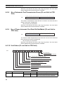
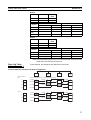
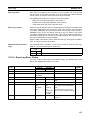
Network Management
Table
The network management table manages information that is shared by all
nodes on the network.
Item
20
Bytes
Contents (data range)
Token holding node number
1 byte
Node currently holding the token
Minimum allowable frame interval
1 byte
Unit: 100 µs
Allowable refresh cycle time
2 bytes
Unit: 1 ms
Refresh cycle measurement value
(current)
2 bytes
Unit: 1 ms
Refresh cycle measurement value
(maximum)
2 bytes
Unit: 1 ms
Refresh cycle measurement value
(minimum)
2 bytes
Unit: 1 ms
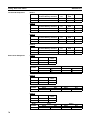
Section 2-2
Cyclic Transmission
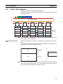
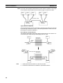
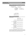
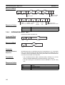
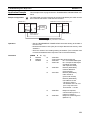
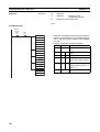
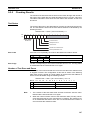
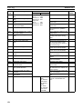
2-2
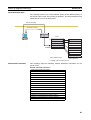
Cyclic Transmission
Cyclic transmission is used to transmit cyclic data.
The data is shared by each node through the Common Memory (shared
memory) function.
Token
Data
FL-net (Ver. 2.00)
Node 1
Node 2
Node 1
Node 1
Node 3
Node...
Node 1
Node 1
3П.ɢ
Ά
Node n
Node 1
3П.ɠ
3П.ɠ
3П.ʐ
Node 2
Node 2
Node 2
Node 2
Node 2
Node 3
Node 3
Node 3
Node 3
Node 3
Node 4
Node 4
Node 4
Node 4
Node 4
Node...
Node...
Node...
Node...
Node...
Node n
Node n
Node n
Node n
Node n
Common
Memory
Note Cyclic transmission allows PLCs made by OMRON to communicate with
PLCs made by other companies.
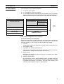
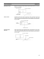
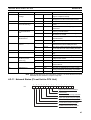
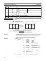
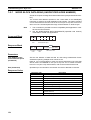
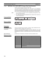
Volume of Transmission
Data
An area of 0.5 Kwords + 8 Kwords = 8.5 Kwords is provided for the whole network.
The maximum quantity of data that can be transmitted by a single node is
8.5 Kwords. One word is equal to two bytes.
15
0
2
2
Area 1
0.5 Kw
Kwords
Common Memory Area
Area 2
8 Kwords
Note With an FL-net Unit, the maximum amount of data that can be transmitted for
each node is 512 words for Area 1 and 7,677 words for Area 2 with a total of
7,677 words for the combined size of Areas 1 and 2.
21
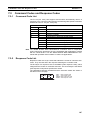
Section 2-3
Message Transmission
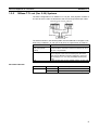
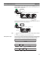
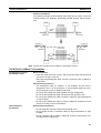
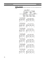
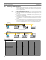
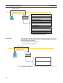
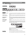
2-3
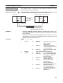
Message Transmission
Message transmission is used to transmit non-cyclic data.
Normally, when a send request is generated, data is transmitted to a specific
node.
Message transmission from node 1 to node 3
Message transmission from node 6 to node 4
FL-net (Ver. 2.00)
1
Note
3
2
4
5
6
1. Message transmission allows OMRON PLCs to communicate with other
manufacturer’s PLCs.
2. Message transmission is performed between OMRON PLCs by executing
the SEND(090), RECV(098), and CMND(490) instructions.
3. Message transmission is performed between OMRON PLCs and other
manufacturer’s PLCs by executing the CMND(490) instruction.
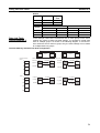
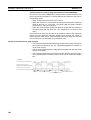
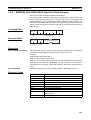
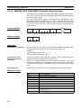
Message Transmissions
The maximum size of one message frame is 1,024 bytes (not including the
header).
Message frame
1,024 bytes
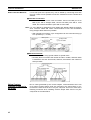
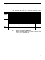
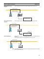
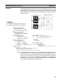
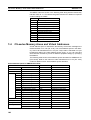
2-4
FINS Communications Service
FINS commands or data can be sent to or received from other manufacturer’s
PLCs on the same FL-net (Ver. 2.00) network by executing SEND(090),
RECV(098), or CMND(490) instructions in the user’s ladder diagram program
in the CPU Unit. This enables control operations such as the reading and writing of I/O memory between PLCs, mode changes, and file memory operations. (When a FINS message is sent on an Ethernet network, a UDP/IP
header is automatically added to the message.)
22
Section 2-4
FINS Communications Service
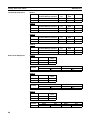
The FINS gateway function allows access not only to OMRON PLCs on the
same FL-net (Ver. 2.00) network, but also to PLCs on other networks such as
SYSMAC LINK or Controller Link.
User program
FinsGateway API
Ethernet
FL-net (Ver. 2.00)
Unit
IP UDP FINS
FL-net (Ver. 2.00)
Unit
FL-net (Ver. 2.00)
Unit
CS-series
PLC
Ethernet Unit
FL-net (Ver. 2.00)
IP UDP FL-net FINS
IP UDP FL-net FINS
User program
SEND/RECV
instruction or
CMND instruction
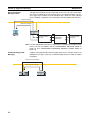
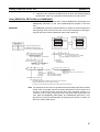
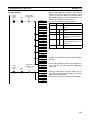
The FINS communications service allows PLC Programming Devices like the
CX-Programmer to be used with a remote PLC.
CX-Programmer
Ethernet
FL-net (Ver. 2.00)
Unit
IP UDP FINS
FL-net (Ver. 2.00)
Unit
CS-series
PLC
Ethernet Unit
FL-net (Ver. 2.00)
IP UDP FL-net FINS
Note
1. The FINS communications service can send messages between OMRON
PLCs.
2. It cannot send messages to other manufacturer’s PLCs.
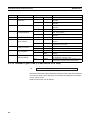
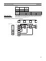
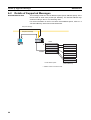
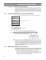
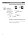
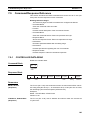
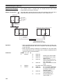
Message Data Length
The FL-net (Ver. 2.00) Unit creates FINS communications messages through
FL-net (Ver.2.00) message transmission. Maximum length for a FINS communications message is 1,024 bytes (including the FINS header and text).
FL-net (Ver. 2.00) message frame
1,024 bytes
FINS header
10 bytes
FINS header
10 bytes
Command
code
Text
2 bytes
1,012 bytes
Command Completion
code
code
2 bytes
2 bytes
Text
1,010 bytes
23
SECTION 3
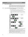
Startup Procedure
This section explains the procedure for starting up the FL-net (Ver. 2.00) Unit, including mounting to the PLC, making the
required settings, and checking communications.
3-1
Before Operation. . . . . . . . . . . . . . . . . . . . . . . . . . . . . . . . . . . . . . . . . . . . . . .
26
3-2
Initial Setup . . . . . . . . . . . . . . . . . . . . . . . . . . . . . . . . . . . . . . . . . . . . . . . . . . .
27
3-3
Nomenclature and Functions . . . . . . . . . . . . . . . . . . . . . . . . . . . . . . . . . . . . .
28
3-4
Hardware Setup. . . . . . . . . . . . . . . . . . . . . . . . . . . . . . . . . . . . . . . . . . . . . . . .
30
3-5
Mounting to the PLC. . . . . . . . . . . . . . . . . . . . . . . . . . . . . . . . . . . . . . . . . . . .
33
3-6
Network Installation . . . . . . . . . . . . . . . . . . . . . . . . . . . . . . . . . . . . . . . . . . . .
34
3-7
Connecting to the Network . . . . . . . . . . . . . . . . . . . . . . . . . . . . . . . . . . . . . . .
44
3-7-1
Connecting the Cable . . . . . . . . . . . . . . . . . . . . . . . . . . . . . . . . . . . .
45
3-7-2
Connecting the Power Supply (CS1W-FLN02 Only). . . . . . . . . . . .
47
3-8
3-9
Creating an I/O Table . . . . . . . . . . . . . . . . . . . . . . . . . . . . . . . . . . . . . . . . . . .
49
3-8-1
I/O Table Overview. . . . . . . . . . . . . . . . . . . . . . . . . . . . . . . . . . . . . .
49
3-8-2
Connecting Programming Devices to the PLC. . . . . . . . . . . . . . . . .
49
3-8-3
Procedure for Creating an I/O Table. . . . . . . . . . . . . . . . . . . . . . . . .
50
Creating Routing Tables . . . . . . . . . . . . . . . . . . . . . . . . . . . . . . . . . . . . . . . . .
50
3-9-1
Routing Table Overview . . . . . . . . . . . . . . . . . . . . . . . . . . . . . . . . . .
51
3-9-2
Connecting and Using a Peripheral Device for the PLC . . . . . . . . .
52
3-10 System Setup. . . . . . . . . . . . . . . . . . . . . . . . . . . . . . . . . . . . . . . . . . . . . . . . . .
55
3-10-1 When Settings are Required . . . . . . . . . . . . . . . . . . . . . . . . . . . . . . .
55
3-10-2 Using the FL-net Unit Support Tool (for OMRON FL-net Units Only)
55
3-10-3 CPU Bus Unit System Setup Defaults . . . . . . . . . . . . . . . . . . . . . . .
55
3-11 Checking Communications . . . . . . . . . . . . . . . . . . . . . . . . . . . . . . . . . . . . . . .
55
3-11-1 PING Command and Internode Testing . . . . . . . . . . . . . . . . . . . . . .
56
3-11-2 PING Command . . . . . . . . . . . . . . . . . . . . . . . . . . . . . . . . . . . . . . . .
56
3-11-3 Internode Test . . . . . . . . . . . . . . . . . . . . . . . . . . . . . . . . . . . . . . . . . .
56
25
Section 3-1
Before Operation
3-1
Before Operation
Precautions
Observe the following precautions when installing and using an FL-net (Ver.
2.00) Unit.
Installation Precautions
Observe the following precautions when installing an FL-net (Ver. 2.00) Unit.
• Make sure that all of the nodes in the network support FL-net version
2.00. Connection will not be possible with FL-net version 1.00.
• Use a transceiver cable that complies with the IEEE802.3 standards to
ensure high noise resistance.
• Use a transceiver with a current consumption of not more than 0.4 A per
port.
• Always turn OFF the power supply to the PLC before connecting or disconnecting the transceiver cable.
• The current consumption of the FL-net Unit is 400 mA maximum. Make
sure that the total current consumption of all Units mounted to the PLC is
mounted does not exceed the capacity of the Power Supply Unit.
• Do not lay the coaxial cables and transceiver cables of the network near
power lines. If installation near possible noise sources is unavoidable, be
sure to take adequate measures against noise interference, such as
installing cables in metal ducts.
Restrictions on Number of
Data Link Nodes
The maximum number of data link nodes that can be used with the FL-net
(Ver. 2.00) Unit is 96 when links are stored in the CPU Unit, and 128 when
links are stored in the FL-net (Ver. 2.00) Unit.
Restrictions on Data Link
Capacity for Each Node
In the Data Link Area for each FL-net (Ver. 2.00) Unit node up to 512 words
can be allocated in Area 1 and up to 7,677 words can be allocated in Area 2.
The total number of words that can be allocated in Areas 1 and 2 combined is
7,677 words.
Restrictions on Data Link
Data Synchronicity
Synchronicity of data within each node is assured, but synchronicity of data
between all nodes is not assured. If a communications packet is corrupted for
some reason, the data prior to the packet being sent will be retained. When
four consecutive token holding timeouts are detected, the respective node in
the Status Area will leave the network and then rejoin, but the PLC data will be
held in its previous state.
Restrictions on Message
Transmissions
When sending messages to other manufacturer's FL-net units, set the message procedure confirmation setting to no confirmation.
Mounting FL-net (Ver.
2.00) Units
• Up to four FL-net (Ver. 2.00) Units can be mounted to a single PLC.
• The current consumption of the FL-net (Ver. 2.00) Unit is 400 mA maximum. (The power supply to the transceiver is not included; it is supplied
by the 24-VDC power supply connected to the power supply terminals on
the Unit.)
Make sure that the total current consumption of all Units mounted to the
CPU Backplane or Expansion Backplane to which the FL-net (Ver. 2.00)
Unit is mounted does not exceed the capacity of the Power Supply Unit.
• When other CPU Bus Units are mounted at the same time as the FL-net
(Ver. 2.00) Unit, make sure that the combined total number of words allocated in the CPU Bus Unit System Setup for each CPU Bus Unit does not
exceed the capacity of the System Setup of the CS-series CPU Unit
(approximately 5 Kwords = 10,752 bytes).
26
Section 3-2
Initial Setup
The size of the CS-series CPU Unit's System Setup Area in an FL-net
(Ver. 2.00) system depends on the operating conditions.
Size = 32 + 10 × Number of remote nodes set (96 nodes max.)
Allocated Size when
Remote Node Allocation
Data is Stored in CPU Unit
Maximum size: 992 bytes (per Unit)
Size = 32 (Number of remote nodes set: 128 nodes max.)
Allocated Size when
Remote Node Allocation
Data is Stored in FL-net
(Ver. 2.00) Unit
3-2
Maximum size: 32 bytes (per Unit)
When the allocation data for remote nodes is stored in the FL-net (Ver. 2.00)
Unit, the CPU Unit System Setup size is 32 bytes per Unit regardless of the
number of remote nodes set.
Initial Setup
Item
Set the unit number.
Set the IP Address (node
address).
Mount the Unit to the Backplane.
Connect to the network.
Procedure
Set a unique number for the Unit so it can operate as a
CPU Bus Unit.
Set the IP address either by the hardware method or software method (using the Support Tool). Select the setting
method in the System Setup.
References
3-4 Hardware Setup
Mount the Unit to the Backplane.
3-4 Hardware Setup
4-2 CPU Bus Unit System
Setup
3-5 Mounting to the PLC
Connect the Unit to the network using the transceiver
cable.
3-7 Connecting to the Network
Connect to the 24-VDC power Connect a 24-VDC external power supply to the power
supply.
supply terminals on the front of the Unit.
3-7 Connecting to the Network
Turn ON the CPU Unit.
Create I/O tables.
--3-8 Creating an I/O Table
Create routing tables.
System Setup
Restart the Unit.
Turn ON the power supply to the CS-series CPU Unit.
Register the FL-net (Ver. 2.00) Unit in the CPU Unit using
the CX-Programmer.
Always create routing tables for using message communications when multiple CPU Bus Units are mounted to the
same PLC.
Set the operating parameters for the FL-net (Ver. 2.00) Unit
using the FL-net Unit Support Tool.
Restart the Unit (turn ON the power again) so that the data
in the System Setup can be read.
3-9 Creating Routing Tables
SECTION 11 FL-net Unit
Support Tool
---
27
Section 3-3
Nomenclature and Functions
3-3
Nomenclature and Functions
This section explains FL-net (Ver. 2.00) Unit part names, settings, and LED
indicators.
Part Names
CS1W-FLN02, 10Base-5 (Front)
LED Indicators (page 29)
Display the operating status of the Unit.
Unit Number Switch (page 30)
Sets the unit number in one digit hexadecimal.
Node Number Switches (page 31)
Set the Unit’s FINS node number in two digits hexadecimal.
Ethernet Connector (page 44)
Connects the Ethernet transceiver cable.
Power Supply Terminals (page 47)
Connects the external power supply (24 V DC) for the transceiver.
CS1W-FLN12, 10Base-T (Front)
LED Indicators (page 29)
Display the operating status of the Unit.
Unit Number Switch (page 30)
Sets the unit number in one digit hexadecimal.
Node Number Switches (page 31)
Set the Unit’s FINS node number in two digits hexadecimal.
Ethernet Connector (page 44)
Connects the Ethernet twisted-pair cable.
28
Section 3-3
Nomenclature and Functions
CS1W-FLN02/12 (Back)
Local IP Address Setting Switches
Set the Unit’s IP address in 16 digits hexadecimal.
For details refer to Section 3-4.
Individual Ethernet addresses are assigned to all communications devices
connected to an Ethernet system. With the FL-net (Ver. 2.00) Unit, the Ethernet address is shown in 12 digits, hexadecimal, on the right side of the Unit.
Ethernet address (12 digits)
Note The Ethernet address can also be checked by means of the FINS command
CONTROLLER DATA READ (page 109).
LED Indicators
The following table shows the meanings of the LED indicator status.
CS1W-FLN02 (10Base-5)
FLN02
RUN
Name
RUN
FLN12
CS
RUN
HER
TX
RX
Indicator
CS1W-FLN12 (10Base-T)
P/S
PER
LNK
MSG
TS
Color
Green
RUN
HER
TX
RX
Display
Not lit.
Lit.
CS
PER
LNK
MSG
TS
Operating status
Operation stopped.
Unit hardware error.
Normal operation.
29
Section 3-4
Hardware Setup
Indicator
Name
Color
P/S (See note.) External Power Supply Green
HER
Unit Error
Red
Display
Not lit.
Operating status
Not supplying 24-V power to power supply
terminals.
Lit.
Supplying 24-V power to power supply terminals.
Not lit.
Lit.
Unit normal.
Hardware error in Unit or EEPROM error.
Communications cable error (at Unit startup).
IP address setting error.
Node address setting error.
Node number duplication.
Disabled because connected to FL-net (Ver.
1.00) network.
CPU Unit normal.
Flashing.
PER
CPU Unit Error
Red
Not lit.
Lit.
TX
Sending Data
Yellow
Not lit.
CPU Unit error.
I/O table error, system setup data error, or
routing table error.
Unit number setting error
Not sending data. (Ready to send.)
Sending data.
Not receiving data. (Ready to receive.)
RX
Receiving Data
Yellow
Lit.
Not lit.
LNK
Servicing FA Link
Yellow
Lit.
Not lit.
Receiving data.
Not connected to FA Link Network.
MSG
Transferring messages Yellow
Lit.
Not lit.
Connected to FA Link Network.
Not transferring messages.
TS
Internode Testing
Lit.
Not lit.
Transferring messages.
Not running internode test.
Lit.
Running internode test.
Yellow
Note CS1W-FLN02 only.
3-4
Hardware Setup
This section explains how to set the various switches on the FL-net (Ver. 2.00)
Unit.
Setting the Unit Number
The unit number is used to identify individual CPU Bus Units when more than
one CPU Bus Unit is mounted to the same PLC. Use a small screwdriver to
make the setting, taking care not to damage the rotary switch. The unit number is factory-set to 0.
Setting range
0 to F
Note
1. Turn OFF the power supply before setting the unit number.
2. If the unit number is being set for the first time or changed, then an I/O table
must be created for the PLC.
■ Unit Number and CPU Bus Unit Allocations
With CS-series PLCs, words are automatically allocated in the CIO Area and
the DM Area according to the unit numbers that are set. The FL-net (Ver.
2.00) Unit uses these words for receiving control data from the CPU Unit and
for notifying the CPU Unit of FL-net (Ver. 2.00) Unit and communications sta-
30
Section 3-4
Hardware Setup
tus. The word addresses in the allocated areas for the CPU Bus Unit are
important in creating the user program for using the FL-net (Ver. 2.00) Unit, so
be careful to take them into account when setting the unit number.
The following table shows the areas allocated for the CPU Bus Unit by unit
number. This table only shows the correspondences between unit numbers
and the words allocated for the CPU Bus Unit. For details, refer to SECTION 4
System Setup and Memory Allocations.
Words Allocated in CIO Area
Unit No.
(decimal)
Allocated words
Unit No.
(decimal)
Allocated words
0 (0)
1 (1)
CIO 1500 to CIO 1524
CIO 1525 to CIO 1549
8 (8)
9 (9)
CIO 1700 to CIO 1724
CIO 1725 to CIO 1749
2 (2)
3 (3)
CIO 1550 to CIO 1574
CIO 1575 to CIO 1599
A (10)
B (11)
CIO 1750 to CIO 1774
CIO 1775 to CIO 1799
4 (4)
5 (5)
CIO 1600 to CIO 1624
CIO 1625 to CIO 1649
C (12)
D (13)
CIO 1800 to CIO 1824
CIO 1825 to CIO 1849
6 (6)
7 (7)
CIO 1650 to CIO 1674
CIO 1675 to CIO 1699
E (14)
F (15)
CIO 1850 to CIO 1874
CIO 1875 to CIO 1899
Words Allocated in DM Area
Unit No.
(decimal)
Setting the Node Number
Allocated words
Unit No. (decimal)
Allocated words
0 (0)
1 (1)
D30000 to D30099
D30100 to D30199
8 (8)
9 (9)
D30800 to D30899
D30900 to D30999
2 (2)
3 (3)
D30200 to D30299
D30300 to D30399
A (10)
B (11)
D31000 to D31099
D31100 to D31199
4 (4)
D30400 to D30499
C (12)
D31200 to D31299
5 (5)
6 (6)
D30500 to D30599
D30600 to D30699
D (13)
E (15)
D31300 to D31399
D31400 to D31499
7 (7)
D30700 to D30799
F (16)
D31500 to D31599
Set the node number, which is the least significant digit of the FL-net (Ver.
2.00) Unit's IP address. Use the Node Number Switches to set the node number to a hexadecimal number from 01 and F9 (1 to 249 decimal). Do not set a
number that has already been set for another FL-net (Ver. 2.00) Unit on the
same network.
Setting range
01 to F9 (1 to 249 decimal)
The left switch sets the leftmost digit (most significant digit) and the right
switch sets the rightmost digit (least significant digit). The node number is factory-set to 01.
If the System Setup is selected as the IP address setting method in the System Setup, the rotary switch settings are not used. To set the rotary switch values for the node number, the value must be set between 01 and F9
hexadecimal. If values outside the specified range are set, the HER indicator
will flash.
Note Turn OFF the power supply before setting the node number.
31
Section 3-4
Hardware Setup
■ Relationship between Node Numbers and IP Addresses
OMRON FL-net (Ver. 2.00) Units are provided with four methods for setting IP
addresses. The setting method is selected in the CPU Bus Unit System Setup
allocated in the CPU Unit.
For details on setting methods, refer to 4-2 CPU Bus Unit System Setup.
Be sure to read and understand all of the following information for each setting
method before setting the IP addresses.
IP address setting
method
Node number setting
method
Details
192.168.250 + node
number
Rotary switches on front of
This is the default FL-net netUnit (Node Number Switches) work address. The node number is set using the rotary
switches on the front of the
Unit.
Rotary switches on
back of Unit.
Rotary switches SW7 and
SW8 on back of Unit
Rotary switch on
back of Unit + node
number
System Setup
The entire IP address is set
using the rotary switches on
the back of the Unit. The node
number cannot be changed
by altering the settings of the
rotary switches on the front of
the Unit. Use this method
when the IP address that was
set when the Unit was
installed does not require
changing.
Rotary switches on front of
The network address is set
Unit (Node Number Switches) using the rotary switches on
the back of the Unit and the
node number is set using the
rotary switches on the front of
the Unit. Use this method
when not using the default
network address. (Rotary
switches SW7 and SW8 on
the back of the Unit are not
used.)
Fourth octet of IP address
The IP address can be set
(rightmost eight bits of the IP when writing the System
address)
Setup data using the FL-net
Unit Support Tool. The values
set on the rotary switches on
the front and back of the Unit
are ignored.
Use this method when frequently changing IP
addresses after installing the
FL-net (Ver. 2.00) Unit, or
when the FL-net (Ver. 2.00)
Unit is not easily accessible.
Note After changing IP addresses or other settings with any of these setting methods, restart the FL-net (Ver. 2.00) Unit.
Setting the Local IP
Address
32
The nodes on an FL-net (Ver. 2.00) network are identified by IP addresses.
Each IP address is set with 32 bits of binary data. These 32 bits are divided
into four 8-bit fields called octets, and the address is expressed as four decimal numbers separated by dots. At the FL-net (Ver. 2.00) Unit, four bits are
expressed as a hexadecimal digit, and the eight hexadecimal rotary switches
(the Local IP Address Switches) on the back of the Unit are used to set the
local IP address. Set the eight switches in hexadecimal as shown below, combining SW1 and SW2, SW3 and SW4, SW5 and SW6, and SW7 and SW8.
Each switch can be set from 0 to F
Section 3-5
Mounting to the PLC
Setting range
0 to F
Local IP Address
The switches are all factory-set to 0 (00.00.00.00). The FL-net (Ver. 2.00) Unit
cannot be used with this setting; a proper IP address must be set. The following settings cannot be made for the IP address, or the HER indicator will flash.
All bits in the network number field set to 0 or 1.
All bits in the host number field set to 0 or 1.
All bits in the subnet number field set to 1.
The beginning of the IP address set to 127 (7F Hex)
Example: 127.35.21.16
Note If a subnet mask is to be set, use the Support Tool to set it in the CPU Bus
Unit Setup Area. For details, refer to SECTION 11 FL-net Unit Support Tool.
3-5
Mounting to the PLC
FL-net (Ver. 2.00) Units can be mounted to any slots in either a CS-series
CPU Rack or a CS-series Expansion Rack, but the number of slots to which
they can be mounted depends on the Backplane. Up to four FL-net (Ver. 2.00)
Units can be mounted to a single PLC. If an FL-net (Ver. 2.00) Unit is mounted
in combination with other CPU Bus Units (e.g., Controller Link Units), the
maximum total number of CPU Bus Units that can be mounted is 16.
33
Section 3-6
Network Installation
Note PLC Backplane mounting screws to a torque of 1.2 N⋅m, and the Unit's
mounting screws to a torque of 0.8 N⋅m.
CS1W-BC023/033/053/083/103 Backplane
CS-series CPU Rack
Can mount to any
position with 2, 3, 5, 8,
or 10 slots.
2, 3, 5, 8, or 10 slots (Expansion Backplane not
possible with 2-slot CPU Backplane.)
CS1W-B1033/053/083/103 Expansion Backplane for CS Series
CS-series Expansion Rack
Can mount to any position
with 3, 5, 8, or 10 slots.
Up to four Units can
be mounted to the
slots shown in the
diagram to the left.
3, 5, 8, or 10 slots
Expansion I/O Backplane for C200H Series
C200H-series I/O
Expansion Rack
Can mount to any slot
position.
CPU: CPU Unit
PS: Power Supply Unit
Note
1. The current consumption of the CS1W-FLN02 or CS1W-FLN12 FL-net
(Ver. 2.00) Unit is 400 mA maximum (not including the power supply to the
transceiver, which is supplied by the 24-VDC power supply connected to
the power supply terminals).
Make sure that the total current consumption of all Units mounted to the
CPU Rack or Expansion Rack to which the FL-net (Ver. 2.00) Unit is
mounted does not exceed the capacity of the Power Supply Unit.
2. When other CPU Bus Units are mounted to the same PLC as the FL-net
(Ver. 2.00) Unit, make sure that the total number of words allocated in the
CPU Bus Unit System Setup of all CPU Bus Units does not exceed the capacity of the CS-series CPU Unit System Setup (approximately 5 Kwords
= 10,752 bytes). When more than one FL-net (Ver. 2.00) Unit with 50 or
more nodes registered are mounted to the same PLC, set the system to
store settings in the FL-net (Ver. 2.00) Units.
3-6
Network Installation
Basic Installation
Precautions
• Take the greatest care when installing the Ethernet System, being sure to
follow ISO 8802-3 specifications. You must obtain a copy of these specifications and be sure you understand them before attempting to install an
Ethernet System. Unless you are already experienced in installing communications systems, we strongly recommend that you employ a professional to install your system.
• Do not install Ethernet equipment near sources of noise. If noise-prone
environments are unavoidable, be sure to take adequate measures
against noise interference, such as installing network components in
grounded metal cases, using optical links in the system, etc. Further information on measures that can be taken against noise is given later in this
section.
34
Section 3-6
Network Installation
Recommended
Products
The following products are recommended for use with the FL-net (Ver. 2.00)
Unit.
CS1W-FLN02 (10Base-5)
Part
Company
Model
Transceiver
Hirakawa Hewtech Corp.
Mitsubishi Cable Industries, Ltd.
MTX-210TZ
ET-10081
Transceiver cable
Mitsubishi Cable Industries, Ltd.
Transceiver cables
(molded type)
24-VDC Power Supply
OMRON
S82J Series
CS1W-FLN12 (10Base-T)
Part
Hub
Twisted-pair
cable
Maker
Allied Telesis
---
Model
number
RH509E
Specifications
9-port hub
MR820TLX
9-port hub with 10Base-5 backbone
port
---
Category 3, 4, or 5 UTP (unshielded
twisted-pair) cable
CS1W-FLN02 (10Base-5) Precautions
Coaxial Cable Installation
Precautions
Basic Precautions
• As a rule, always lay coaxial cables indoors. Laying coaxial cables outdoors requires special measures that should be performed only by a professional. If coaxial cable must be used outdoors, request the work from a
professional.
• Attach a terminator to each end of the coaxial cable.
• Cover all exposed metal portions of the coaxial cable except ground
points with protective covers or PVC tape to prevent contact with grounds
or other metal objects.
• Ground the external shield of the coaxial cable to 100 W or less using
AWG 14 wire (cross-sectional area of 2 mm2) or better and a ground
cable length of 20 m or less. Ground each segment of the network at one
location only. Do not use the same ground for other equipment.
• The physical properties (e.g., minimum bending radius) of coaxial cable
vary with the manufacturer. Follow all recommendations and specifications of the manufacturer.
Environmental Precautions
• Do not install coaxial cables together with power cables.
• Do not install coaxial cable near sources of noise.
• Do not install coaxial cable in environments subject to excessive dirt,
dust, oil mist, etc.
• Do not install coaxial cable in environments subject to high temperatures
or high humidity.
Terminator Installation
Precautions
Basic Precautions
• You must attach a Terminator to each end of the coaxial cable for communications to be possible.
• Insulate Terminators when attaching them to be sure they do not come
into contact with metal objects.
35
Section 3-6
Network Installation
Transceiver Installation
Precautions
Basic Precautions
• Transceivers can be attached to coaxial cables only at intervals of 2.5 m.
These locations should be marked on the cable.
• Connection methods can vary with the manufacturer of the cable. Follow
all recommendations and specifications of the manufacturer.
• Mount the transceiver onto an insulating object, such as a wooden board.
• Ground the transceiver through the shield of the transceiver cable and
through the FL-net (Ver. 2.00) Unit.
Environmental Precautions
• Do not install transceivers near sources of noise.
• Do not install coaxial cable in environments subject to excessive dirt,
dust, oil mist, etc.
• Do not install coaxial cable in environments subject to high temperatures
or high humidity.
Transceiver Cable
Installation Precautions
Basic Precautions
• Make sure that the transceiver cable is firmly and completely connected
to both the transceiver and the FL-net (Ver. 2.00) Unit. Be sure that the
slide latches are engaged.
Environmental Precautions
• Do not install transceiver cables together with power cables.
• Do not install transceiver cable near sources of noise.
• Do not install transceiver cable in environments subject to high temperatures or high humidity.
Grounding
• Ground all devices requiring grounding to 100 W or less using AWG 14
wire (cross-sectional area of 2 mm2) or better and a ground cable length
of 20 m or less. Electrical shock can occur between ungrounded devices
in the system. The lack of proper grounds can also corrupt data.
• Use one safety ground on each segment of the network.
• Inductive voltages can be generated due to lightning surges when coaxial
cable is installed outdoors, requiring special measures. Request outdoor
installation from a professional.
Transceiver Installation
Examples
36
The following illustrations show examples of installing transceivers in the ceiling and under the floor.
Section 3-6
Network Installation
Ceiling and Floor Installation
Inspection opening
Secured wooden
board
Mount near an inspection
opening large enough to
enable maintenance.
Secured
wooden board
Free-access Floor Installation
37
Section 3-6
Network Installation
Ceiling Installation
Coaxial cable (above ceiling)
Secured
wooden
board
Transceiver
Distribution panel
Metal duct
Duct
Corner box
Transceiver cable
Wire protector
Installation Examples
for Noise-prone
Environments
Ethernet networks do not withstand noise very well and require special installation measures if installed where subject to noise. The examples provided
here show measures for dealing with noise.
The message service function does not guarantee that the message will
arrive at the other node. To ensure that the message is received when using
the message service function, resend processing is normally executed at the
node sending the instruction. With the SEND(090), RECV(098), and
CMND(490) instructions, resend processing is executed automatically for the
specified number of resends, so be sure to specify a number other than 0.
38
Section 3-6
Network Installation
Metal Ducts
1.
Distribution box
2.
CS1W-FLN02
CS-series PLC
3.
4.
Transceiver
cable
Noise
Place the coaxial cable in metal
ducts.
Place transceivers into metal boxes, placing a wooden board or other
insulating board between the box
and the transceiver. The transceiver
and the metal box must be electrically insulated from each other.
If the transceiver cable is also in a
noise-prone area, place it into a
metal duct as well.
Refer to the CS Series Programmable Controllers Operation Manual
for information on wiring inside distribution boxes.
Metal duct
Wooden
board
Metal duct
Transceiver
Metal box for
transceiver
Metal box for
transceiver
Noise
Note
1. Cover all metal portions of cables with insulating tape to be sure they do
not come into contact with the metal ducts or boxes.
2. Securely ground all distribution boxes and metal boxes around transceivers. The lower the ground resistance, the more effective the shields will be.
3. The twisted-pair cable for 10Base-T is not shielded, and the hub is designed for use in OA environments. In environments subject to noise, we
recommend the use of 10Base-5 Ethernet.
Multiport Transceivers
Multiport transceivers can be used to eliminate the need for coaxial cable
(which is easily affected by noise) and replace it with transceiver cable as
shown in the following diagram. This will increase overall system resistance to
noise.
39
Section 3-6
Network Installation
Note Up to two sets of multiport transceivers can be used in a network. The length
of the network will be limited to the maximum length of transceiver cable.
Node
Node
Node
Node
Node
Transceiver cable
Multiport
transceiver
Multiport
transceiver
Optical Ethernet Systems
Some manufacturers provide optical fiber components for Ethernet networks
to provide high resistance to noise. The following illustrations show some simple examples of optical installations.
Use as Noise Countermeasure
The following illustration shows how optical components can be used to convert to fiber-optic cable through areas highly prone to noise.
Node
Node
Noise-prone
environment
Coaxial
cable
Transceiver
Transceiver
Segment 2
Segment 1
Coaxial
cable
Transceiver
Optical
transceiver
Repeater
Note
Coaxial
cable
Transceiver
Fiber-optic cable Noise-prone
environment
Optical
transceiver
Repeater
1. Install the transceiver itself in a noise-free location.
2. Contact the manufacturer for details on optical fiber devices.
40
Section 3-6
Network Installation
Outdoor Installations
The following example shows how fiber-optic cable can be used to connect a
network between two buildings, eliminating possible adverse affects of lightning.
Node
Node
Noise-prone
environment
Coaxial
cable
Transceiver
Transceiver
Segment 2
Segment 1
Coaxial
cable
Transceiver
Coaxial
cable
Transceiver
Fiber-optic cable Noise-prone
environment
Optical
transceiver
Repeater
Optical
transceiver
Repeater
Note Contact the manufacturer for details on optical fiber devices.
CS1W-FLN12 (10Base-T) Precautions
Precautions on Laying
Twisted-pair Cable
Basic Precautions
• Press the cable connector in firmly until it locks into place at both the hub
and the FL-net (Ver. 2.00) Unit.
• After laying the twisted-pair cable, check the connection with a 10Base-T
cable tester.
Environment Precautions
• The twisted-pair cable for 10Base-T is not shielded, and the hub is
designed for use in OA environments. In environments subject to noise,
we recommend the use of 10Base-5 Ethernet.
• Do not lay the twisted-pair cable together with high-voltage lines.
• Do not lay the twisted-pair cable near devices that generate noise.
• Do not lay the twisted-pair cable in locations subject to high temperatures
or high humidity.
• Do not lay the twisted-pair cable in locations subject to excessive dirt and
dust or to oil mist or other contaminants.
Hub Installation
Precautions
Environment Precautions
• Do not install the hub near devices that generate noise.
• Do not install the hub in locations subject to high temperatures or high
humidity.
• Do not install the hub in locations subject to excessive dirt and dust or to
oil mist or other contaminants.
41
Section 3-6
Network Installation
Hub Connection Methods
If more hub ports are required, they can be added by connecting more than
one hub. There are two possible connection methods for hubs: Cascade and
stacked.
■ Cascade Connections
• Connect two hubs to each other as follows: Connect an MDI port to an
MDI-X port with a straight cable; connect two MDI ports with a cross
cable; and connect two MDI-X ports with a cross cable.
Note It is very difficult to distinguish cross cables and straight cables by appearance. Incorrect cables will cause communications to fail. We recommend
using straight cables whenever possible.
• With cascade connections, up to 5 segments can be connected using up
to 4 repeaters (i.e., 4 hubs).
MDI-X port
(cross)
MDI-X ports
Straight cable
Hub
Cross cable
Hub
Hub
Hub
■ Stack Connections
• Connect the hubs using special cables or special racks.
• Normally there is no limit to the number of hubs in a stack, and each stack
is treated as one hub. Some hubs, however, are limited in the number of
hubs per stack.
Hub
Four stackable hubs
Stack
cable
Using Contact
Outputs (Common to
All Units)
42
Two stackable hubs
Stack
cable
Due to noise generated by the contact outputs, communications errors can
occur when Contact Output Units are mounted to the same Rack or connected to the same PLC as an FL-net (Ver. 2.00) Unit. Use one or more of the
following measures when installing Contact Output Units and FL-net (Ver.
2.00) Units on the same Rack.
Section 3-6
Network Installation
Mounting Location
Mount (or connect) any Contact Output Units as far away from the FL-net (Ver.
2.00) Unit as possible.
Contact Output Unit
FL-net (Ver. 2.00) Unit
Transceiver/Hub
Contact outputs
Cable Location
Separate the transceiver cable or twisted-pair cable connecting the Unit as far
from the wiring to the Contact Output Units as possible. The coaxial cable
must also be placed as far away from the Contact Output Units and their wiring as possible.
Contact outputs
Contact
Output Unit
FL-net
(Ver. 2.00)
Unit
To Transceiver/Hub
Transceiver/Hub
Measures
Attach several ferrite cores designed for EMI countermeasures on the transceiver cable or twisted-pair cable near the transceiver/hub. The transceiver
must also be placed as far away from the Contact Output Units and their wiring as possible.
FL-net (Ver. 2.00) Unit
Ferrite cores
Transceiver/Hub
Transceiver
cable
43
Section 3-7
Connecting to the Network
3-7
Connecting to the Network
Ethernet Connectors
CS1W-FLN02
The following standards and specifications apply to the connectors for the
Ethernet transceiver cable.
• Electrical specifications: Conforming to IEEE802.3 standards
• Lock structure:
Connector
pin
1
2
Signal name
Abbr.
Signal direction
GND
COL+
3
Signal ground
Collision detection
signal +
Send data +
TX+
Output
4
5
Signal ground
Receive data +
GND
RX+
--Input
6
Power ground (common with signal
ground)
Not used
VC
---
---
---
7
--Input
8
9
Signal ground
Collision detection
signal –
GND
COL–
--Input
10
11
Send data –
Signal ground
TX–
GND
Output
---
12
13
Receive data –
RX–
Transceiver +12 VDC +12 V
power supply
Signal ground
GND
---
Not used
Frame ground
-----
14
15
Connector
hood
CS1W-FLN12
IEEE802.3 standards for slide latches
--FG
Input
Output
The following standards and specifications apply to the connectors for the
Ethernet twisted-pair cable.
• Electrical specifications: Conforming to IEEE802.3 standards.
• Connector structure:
44
RJ45 8-pin Modular Connector
(conforming to ISO 8877)
Section 3-7
Connecting to the Network
3-7-1
Connector
Signal name
pin
1
Transmission data +
Abbr.
TD+
Signal
direction
Output
2
3
Transmission data –
Reception data +
TD–
RD+
Output
Input
4
5
Not used.
Not used.
-----
-----
6
7
Reception data –
Not used.
RD–
---
Input
---
8
Not used.
---
---
Connecting the Cable
Transceiver Cable (for CS1W-FLN02)
!Caution Turn OFF the PLC’s power supply before connecting or disconnecting transceiver cable.
1,2,3...
1. Prepare a coaxial cable.
2. Connect the transceivers to the coaxial cable.
• Mark the coaxial cable at intervals of 2.5 meters. Then connect the
transceivers at those marks.
• The transceiver connection method depends on the type of transceiver, so refer to the transceiver operation manual.
3. Prepare the transceiver cable, and then connect it to the transceivers.
The cable preparation should be performed by an experienced professional.
4. Connect the transceiver cable to the FL-net (Ver. 2.00) Unit connector. The
FL-net (Ver. 2.00) Unit connector has a slide latch conforming to
IEEE802.3 specifications that serves as a lock mechanism. To connect the
transceiver cable, operate the slide latch as described below.
a) First push the slide latch upwards.
b) Insert the cable connector into the FL-net (Ver. 2.00) Unit’s connector
with the two locking posts at the end of the cable connector aligned
with the holes in the slide latch.
45
Section 3-7
Connecting to the Network
c) Then push the slide latch down to lock the cable connector in place.
Lock post
Slide latch
CS1W-FLN02
Lock post
Twisted-pair Cable (for CS1W-FLN12)
!Caution Turn OFF the PLC’s power supply before connecting or disconnecting twistedpair cable.
1,2,3...
1. Lay the twisted-pair cable.
2. Connect the cable to the hub. Be sure to press in the cable until it locks into
place.
Examples of the above two steps are provided in Appendix A. Request cable installation from a qualified professional.
3. Connect the cable to the connector on the FL-net (Ver. 2.00) Unit. Be sure
to press in the cable until it locks into place.
Example: CS1W-FLN12
RJ45 Modular Connector
CS1W-FLN12
46
Section 3-7
Connecting to the Network
3-7-2
Connecting the Power Supply (CS1W-FLN02 Only)
Connect a 24-VDC power supply to the power supply terminals. The FL-net
(Ver. 2.00) Unit converts this 24-VDC power supply to the power supply voltage for the transceivers and provides it through the transceiver cable.
24-VDC input
24-VDC power supply
Crimp terminals must be used for the power supply cable. The applicable M3
crimp terminals and recommended products are shown below.
6.2 mm max.
Maker
J.S.T.MFG.CO.,
LTD
Model
Specifications
V1.25-N3A
Fork terminal with
vinyl insulation
Ring terminal with
vinyl insulation
0.25 to 1.65 mm2
(AWG: #22 to #16)
VSY1.25-3.5L
Fork terminal with
vinyl insulation
0.3 to 1.65 mm2
(AWG: #22 to #16)
RAV1.25-M3
Ring terminal with
vinyl insulation
V1.25-MS3
MOLEX JAPAN
CO.,LTD
6.2 mm max.
Applicable power line
range (stranded wire)
!Caution Be sure to turn OFF the power supply to the PLC before connecting to the
power supply terminal block.
Note
1. Do not connect a power supply with a voltage other than 24 VDC.
2. To reduce the effects of noise, wire the power supply cable separately from
power lines and high-voltage lines.
3. Crimp terminals must be used for wiring. Do not just twist loose wire
strands.
4. Use the recommended crimp terminals.
5. Use the proper tools and procedure for installing the crimp terminals. Consult with the terminal manufacturers for instructions. If the proper tools and
procedure are not used, it may cause the cable to become disconnected.
6. When installing the crimp terminals, use a length of cable that will not need
to be bent too much when combined with the terminals. Also, cover the terminal and the end of the cable with insulating tape and heat-absorbing tubing.
7. Be careful not to mistake the plus and minus terminals when connecting
the power supply.
8. Tighten the terminal block screws to a torque of 0.5 N·m. If the screws are
too loose, it may result in short-circuiting, malfunctioning, or fire damage.
9. Check the wiring carefully before turning ON the power.
10. Use a dedicated power supply, and do not use the same power supply for
the I/O power supply, motor power lines, or control power lines.
11. Position the power supply as close as possible to the Unit, and separate
the power supply cable by at least 20 cm from other power lines in order to
avoid adverse effects from high-voltage lines.
47
Section 3-7
Connecting to the Network
12. Noise influence may be reduced by installing a noise filter near the primary
side of the power supply.
13. Carefully twist the power supply cable that is to be connected to the Unit.
14. Do not excessively bend or stretch the cable.
15. Do not place anything on top of cables.
16. If errors occur due to noise related to an external power supply, it may be
possible to solve the problem by not grounding the communications power
supply. Normally the switching power supply is connected to the case and
capacitor, as shown in the following diagram, so along with isolating the FG
terminal it is necessary to insulate the power supply itself from the control
panel.
General Switching Power Supply Configuration
Switching power supply
AC power supply
Power
supply
circuit
AC input
DC output
Case
Standard Switching Power Supply Circuit
Communications Power Supply Isolation Method
S82J Power Supply
DC power supply
Insulating material (bakeboard, acrylic board, etc.)
S82Y-@@N (Mounting Stand)
(1) When S82J is used.
(2) When another power supply is used.
17. If communications are adversely affected by noise from the Unit’s power
supply terminals, the problem may be solved by implementing the measures shown below.
a) Add to the communications retry processing at the application. In particular, noise resistance capacity can be improved by increasing the
number of retries for applications using UDP.
b) Insert a noise filter right next to the Unit’s power supply terminals.
24 VDC
24-VDC power supply
Noise filter
As close as possible
Recommended filter: MAS-1206-33 by Nemic-Rambda K.K.
48
Specifications
Rated voltage: 250 V (AC, DC)
Rated current: 6 A
Dimensions
105.5 x 52.5 x 40 mm (W x H x D)
(Not including connector.)
Section 3-8
Creating an I/O Table
Power Supply
Specifications
The following table shows the power supply specifications. Make sure that
these specifications are met.
Item
Power supply voltage
Specifications
24 VDC
Allowable power supply voltage
fluctuation
20.4 VDC to 26.4 VDC (24 VDC –15% + 10%)
Current consumption
Inrush current
300 mA max. at 24 VDC (per node)
2.5 A max. (24 VDC when rise time is 5 ms)
OMRON’s S82J Series is recommended for the power supply.
Note
1. Use a power supply that meets these specifications.
2. If the power supply is separate from a node, make sure that these specifications are met at the node’s terminal block.
3. Turn ON the Unit’s power supply either before or at the same time as the
CPU Unit’s power supply. If the CPU’s power is turned ON first, a communications error may be generated.
4. Use a power supply with double or reinforced insulation.
5. Confirm that the Power Status Bit is ON before starting communications.
(Refer to Power Status (Bit 15) in 4-3 Allocated Words in the CIO Area.)
6. In the IEEE802.3 standards, the transceiver power supply specifications
require a voltage of 11.28 V (12 V – 6%) to 15.75 V (15 V + 5%) at the
transceiver inputs. The voltage output by the FL-net (Ver. 2.00) Unit takes
into account a voltage drop at the transceiver cable.
3-8
Creating an I/O Table
After the hardware settings and connections have been completed, turn ON
the power supply to the PLC and create an I/O table.
3-8-1
I/O Table Overview
An I/O table is used to identify Units connected to the PLC and to allocate I/O
to them. If any change is made to the Unit configuration of a CS-series PLC,
an I/O table must be created to register the Units to the CPU Unit.
3-8-2
Connecting Programming Devices to the PLC
To create the I/O table, connect a Programming Device (such as a Programming Console or CX-Programmer) to the PLC.
Applicable Programming
Devices
The following Programming Devices can be used with CS-series PLCs.
Programming Console
Model number
C200H-PRO27-E
Key Sheet (required)
CS1W-KS001-E
CQM1-PRO01-E
Recommended cable (required)
CS1W-CN224 (cable length: 2.0 m)
CS1W-CN624 (cable length: 6.0 m)
CS1W-CN114 (cable length: 0.1 m)
CX-Programmer and CX-Net
Model number: WS02-CXP@@-EV2
The operations are explained here using a Programming Console. For details
regarding the CX-Programmer and the CX-Net, refer to the CX-Programmer
User’s Manual.
49
Section 3-9
Creating Routing Tables
CX-Net is software that comes with CX-Programmer and is automatically
installed when CX-Programmer is installed.
Connecting Programming
Devices
3-8-3
To connect a Programming Console, attach a CS-series Key Sheet and then
connect the Console to the CPU Unit’s peripheral port. (It cannot be connected to the RS-232C port.)
Procedure for Creating an I/O Table
The procedure for creating an I/O table is shown here, taking as an example
an I/O table that is generated automatically for a PLC connected online. In this
example, a Programming Console is used for creating the I/O table. For an
explanation of how to create an I/O table using a CX-Programmer, refer to the
CX-Programmer User’s Manual.
Use the following procedure to create the I/O table.
Initial screen
SHIFT
CH
*DM
000000 I/O TBL ?
CHG
000000 I/O TBL
WRIT
????
WRITE
Password
000000CPU BU ST?
0:CLR 1:KEEP
or
(Save or clear the CPU Bus Unit System Setup.)
000000 I/O TBL
WRIT OK
3-9
Creating Routing Tables
When the FINS communications service is used, routing tables must be created in advance. Routing tables are required in the following circumstances.
• When the FINS communications service is used on an FL-net (Ver. 2.00)
network (including when communications are only carried out between FA
networks via an FL-net (Ver. 2.00) network).
• When there are multiple Communications Units mounted to the PLC, and
FA Link protocol messages, such as writing or reading word blocks, etc.,
are executed by the CMND(490) instruction.
If neither of these circumstances apply, then a routing table is not required. In
that case, proceed to 3-10 System Setup.
The routing table is required not only for nodes communicating via the FINS
communications service but for all relay nodes on the network.
50
Section 3-9
Creating Routing Tables
3-9-1
Routing Table Overview
The routing tables describe the transmission path for FINS messages when
the FINS communications are used. It consists of two tables: A local network
table and a relay network table.
Local Network Table
The local network table is a table describing the correspondences among unit
numbers of the Communications Units and Boards mounted to each node
(PLC or FA Computer).
Example
Unit #04
Unit #05
Unit #06
Unit #07
Local Network Table
Local network Unit number
address
1
2
3
4
04
05
06
07
Network #1
Network #2
Network #3
Network #4
Note
1. The unit number is set (from 0 to F: 1 to 15) by the rotary switch on the front
of the FL-net (Ver. 2.00) Unit.
2. The network address is the number of the network (from 1 to 127) to which
the Communications Unit or Board is connected. It is set when the local
network table is created.
Relay Network Table
A relay table is a table that shows the nodes to which data should be sent first
in order to send data to a network that is not connected to the local node. It
shows the correspondence between the address of the final destination network, and the network address and node number of the first relay point of the
path to reach there. When internetwork communications are carried out, the
end network can be reached by following the relay points.
51
Section 3-9
Creating Routing Tables
The following example shows a routing table for sending data from PLC #1
(the local node: network address 1, node number 1) to PLC #4 (the destination node: network address 3, node number 2).
Node #2
PC #3
Unit #0
(relay node) Node #1
PC #2 (relay node)
Unit #1
PC #1 (local node)
PC #4 (destination node)
Node #3
Node #1
Node #2
Node #2
Node #1
Network #1
Network #2
PC #1
relay network table
PC #2
relay network table
End
Relay
Relay
network network node
End
Relay
Relay
network network node
To go to network #3,
first go to node #2 at
network #2.
To go to network #3,
first go to node #3 at
network #1.
3-9-2
Network #3
End network
PC #3
relay network table
Local
network
address
Unit
number
(To go to network #3 (The network is the same,
according to the local so go to node #2 at network #3.)
network table, go
through the unit
number of the local
CPU Rack.)
Connecting and Using a Peripheral Device for the PLC
Routing tables must be created by a CX-Net connected to the PLC. (They
cannot be created using a Programming Console.) For details on how to connect and use a CX-Net, refer to the CX-Programmer User’s Manual. (CX-Net
is automatically installed when CX-Programmer is installed.)
Note
1. To transfer routing tables for multiple nodes to a PLC in one batch, connect
the CX-Net to a PLC with only one Communications Unit mounted. Routing
tables cannot be transferred to other nodes from a PLC with multiple Communications Units mounted.
2. Routing tables can only be transferred as a batch to multiple nodes within
the same network as the PLC to which the CX-Net is connected.
52
Section 3-9
Creating Routing Tables
Routing Table Setting Examples
Example 1: Local Network Table for a PLC With Multiple Units Mounted
This example shows the local network table settings for a PLC to which multiple CPU Bus Units are mounted.
FL-net (Ver. 2.00) network
Controller Link network
(Network #B)
(Network #A)
PS: Power Supply Unit
CPU: CPU Unit
FLN: FL-net Unit (Ver. 2.00)
CLK: Controller Link Unit
Unit #a Unit #b
Local Network Table
Local
CPU Bus
network
Unit
Example 2: Three Interconnected Networks
This example shows the relay network table settings for three different interconnected networks.
Relay Network Table
No.
End
network
Relay
network
Node
PC #1
Node #a
Network #A
PC #2
Node #b
Node #c
PC #3
Network #B
Node #d
PC #4
Node #e
Node #f
Network #C
Node #g
In the table for PLC #3, for example, if network #A is taken as the end network, then network #B becomes the relay network and node #c becomes the
relay node. If network #C is taken as the end network, then network #B still
becomes the relay network and node #e becomes the relay node.
53
Section 3-9
Creating Routing Tables
Example 3: All Nodes
This example uses the following configuration to show the routing tables for all
nodes.
Unit #5
Node #6
Network #10
Unit #4
Node #5
Unit #7
Node #15
Network #30
Unit #3
Node #4
Unit #2
Node #3
Network #20
Unit #0
Node #1
PC #1 Routing Table
(Local network table)
Local
CPU Bus
network Unit No.
PC #2 Routing Table
(Local network table)
Local
network
CPU Bus
Unit No.
PC #3 Routing Table
(Local network table)
Local
network
CPU Bus
Unit No.
PC #4 Routing Table
(Local network table)
Local
network
CPU Bus
Unit No.
PC #5 Routing Table
(Local network table)
Local
network
CPU Bus
Unit No.
PC #6 Routing Table
(Local network table)
Local
network
CPU Bus
Unit No.
PC #7 Routing Table
(Local network table)
Local
network
54
CPU Bus
Unit No.
Unit #1
Node #2
Unit #5
Node #5
Unit #6
Node #10
(Relay network table)
End
network
Relay
network
Relay
node
(Relay network table)
End
network
Relay
network
Relay
node
(Relay network table)
End
network
Relay
network
Relay
node
(Relay network table)
End
network
Relay
network
Relay
node
(Relay network table)
End
network
Relay
network
Relay
node
(Relay network table)
End
network
Relay
network
Relay
node
(Relay network table)
End
network
Relay
network
Relay
node
Section 3-10
System Setup
3-10 System Setup
The settings for the FL-net (Ver. 2.00) Unit’s basic and special functions are
made in the CPU Bus Unit System Setup. These settings, and the situations
in which the settings must be made, are shown in the following table. For
details on how to make the settings, refer to 4-2 CPU Bus Unit System Setup.
3-10-1 When Settings are Required
Settings
FA Link mapping table method
When settings are required
When the number of nodes assigned to the table exceeds 96.
FA Link startup method
Confirm message protocol
When using a ladder program to control communications participation after powerup.
When executing message communications with an FL-net (Ver. 2.00) node by
another manufacturer.
Broadcast type
IP address set method
Sub-net mask
When changing the broadcast address for any reason.
When making settings, for any reason, outside of the range of the default IP address
setting method.
When changing the sub-net mask for any reason.
Local node setup
Other node setup
When using the Data Link function.
When using the Data Link function.
3-10-2 Using the FL-net Unit Support Tool (for OMRON FL-net Units
Only)
The settings for the CPU Bus Unit System Setup are made using an FL-net
Unit Support Tool connected to the PLC. The settings cannot be made using a
Programming Console or a CX-Programmer.
3-10-3 CPU Bus Unit System Setup Defaults
The following table shows the items in the CPU Bus Unit System Setup, and
their default settings.
Item
Default
FA Link mapping table method
FA Link startup method
PLC built-in method
Automatic participation method
Confirm message protocol
Broadcast type
Confirm
***.***.***.255
IP address set method
Sub-net mask
192.168.250.node number
255.255.255.0
Local node setup
Other node setup
None
None
3-11 Checking Communications
The FL-net (Ver. 2.00) Unit supports the PING command, which is also widely
supported by host computers. It also supports a function for internode testing
in the FINS communications service by simply manipulating bits with a Programming Device.
After the settings and connections have been completed, use either the PING
command or the internode test function as required to check communications
with the remote nodes.
Networking checks using the PING command and internode testing can be
executed regardless of the PLC’s operating mode, but it may have an effect on
55
Section 3-11
Checking Communications
operation by increasing network traffic and adding more internal processing
for the FL-net (Ver. 2.00) Unit.
It is recommended that the testing be performed with the tested node in PROGRAM Mode, or in an environment in which message servicing is not executed.
3-11-1 PING Command and Internode Testing
The following table outlines the points of difference between the PING command and internode testing.
Item
PING command
Internode testing
Main application
Testing communications as Testing as an FL-net (Ver.
an Ethernet node.
2.00) node.
Test objects
FL-net (Ver. 2.00) Units
and Ethernet devices that
support PING.
FL-net (Ver. 2.00) Units
and devices supporting FLnet (Ver. 2.00).
Network classification
Within Ethernet networks
(including between segments).
Within FL-net (Ver. 2.00)
networks.
Address system used
IP addresses
Node numbers
Transmission from FL-net
(Ver. 2.00) Unit
Cannot be sent from this
Unit.
From Programming
Devices for PLC, set the
required parameters in
CIO words allocated to
CPU Bus Units and turn
ON the Start Bit.
Reception at FL-net (Ver.
2.00) Unit
When PING command is
received, it is automatically returned.
When internode test message is received, it is automatically returned.
3-11-2 PING Command
The PING command checks communications with another node by sending
an echo back request packet and receiving a response packet. Use the PING
command as required to check communications. Using the PING command
from a personal computer on an Ethernet network makes it possible to check
whether Ethernet internode communications are normal.
3-11-3 Internode Test
The internode test is a function for checking a network by sending data to and
from specified nodes and checking the responses. Use the internode test as
required to check the communications between FL-net (Ver. 2.00) nodes. Use
it as required to check message communications.
Note The internode test can be easily carried out by manipulating dedicated control
switches for the FL-net (Ver. 2.00) Unit. For details, refer to 9-3 Internode Test.
56
SECTION 4
System Setup and Memory Allocations
This section explains the System Setup and the words allocated in the CIO Area and the DM Area for FL-net (Ver. 2.00)
Units.
4-1
4-2
4-3
Allocated Words . . . . . . . . . . . . . . . . . . . . . . . . . . . . . . . . . . . . . . . . . . . . . . .
58
CPU Bus Unit System Setup. . . . . . . . . . . . . . . . . . . . . . . . . . . . . . . . . . . . . .
59
4-2-1
FL-net Unit Support Tool and CPU Bus Unit Setup Area Screen . .
60
Allocated Words in the CIO Area . . . . . . . . . . . . . . . . . . . . . . . . . . . . . . . . . .
61
4-3-1
62
Unit Control Bits (CPU Unit to FL-net Unit). . . . . . . . . . . . . . . . . .
4-3-2
Internode Test Destination Address (CPU Unit to FL-net Unit) . . .
62
4-3-3
Internode Test Monitoring Time (CPU Unit to FL-net Unit) . . . . . .
62
4-3-4
Internode Test Status (CPU Unit to FL-net Unit) . . . . . . . . . . . . . . .
62
4-3-5
No. of Internode Test Runs (FL-net Unit to CPU Unit) . . . . . . . . . .
63
4-3-6
No. of Internode Test Timeout Errors (FL-net Unit to CPU Unit) . .
63
4-3-7
No. of Internode Test Response Errors (FL-net Unit to CPU Unit) .
63
4-3-8
No. of Internode Test Transmission Errors (FL-net Unit to CPU Unit)
64
4-3-9
No. of Times Internode Test Data Did Not Match
(FL-net Unit to CPU Unit) . . . . . . . . . . . . . . . . . . . . . . . . . . . . . . . .
64
4-3-10 Unit Status (FL-net Unit to CPU Unit). . . . . . . . . . . . . . . . . . . . . . .
64
4-3-11 Network Status (FL-net Unit to CPU Unit) . . . . . . . . . . . . . . . . . . .
65
4-3-12 Refresh Cycle Time (FL-net Unit to CPU Unit). . . . . . . . . . . . . . . .
66
57
Section 4-1
Allocated Words
4-1
Allocated Words
The FL-net (Ver. 2.00) Unit is allocated words in the following four areas for
reading settings and status.
• System Setup for CPU Bus Units
Stores initial setup for the FL- net (Ver. 2.00) node.
• System Setup in FL- Unit (Ver. 2.00)
Stores Data Link data when the FL-net (Ver. 2.00) Unit’s Data Link function is used with the Unit built-in method.
• Allocated Words in the CIO Area
Stores software switches and status information for functions.
• Allocated Words in the DM Area
Stores software switch and status information for functions.
CPU Unit
FL-net (Ver. 2.00) Unit
CPU Bus Unit System Setup
(Set using FL-net Unit Support Tool.)
Transferred
when power
supply is turned
ON or Unit is
restarted.
to
to
System Setup in FL-net (Ver.
2.00) Unit
(Set by FL-net Unit Support Tool.)
to
Allocated Words in CIO Area for
CPU Bus Units
n = CIO 1500 + 25 x unit number
15
15
0
n
0
I/O refresh
n+1
to
to
n + 24
Allocated Words in DM Area for
CPU Bus Units
n = D30000 + 100 x unit number
0
15
m
15
0
I/O refresh
m+1
to
to
m + 99
The words in the CIO Area and DM Area are allocated according to the unit
number as shown in the following tables. The 25 words are allocated per Unit
in the CIO Area and 100 word are allocated per Unit in the DM Area.
58
Section 4-2
CPU Bus Unit System Setup
CIO Area Allocations
Unit No.
(decimal)
Allocated words
Unit No.
(decimal)
Allocated words
0 (0)
1 (1)
CIO 1500 to CIO 1524
CIO 1525 to CIO 1549
8 (8)
9 (9)
CIO 1700 to CIO 1724
CIO 1725 to CIO 1749
2 (2)
3 (3)
CIO 1550 to CIO 1574
CIO 1575 to CIO 1599
A (10)
B (11)
CIO 1750 to CIO 1774
CIO 1775 to CIO 1799
4 (4)
5 (5)
CIO 1600 to CIO 1624
CIO 1625 to CIO 1649
C (12)
D (13)
CIO 1800 to CIO 1824
CIO 1825 to CIO 1849
6 (6)
7 (7)
CIO 1650 to CIO 1674
CIO 1675 to CIO 1699
E (14)
F (15)
CIO 1850 to CIO 1874
CIO 1875 to CIO 1899
DM Area Allocations
Unit No.
(decimal)
4-2
Allocated words
Unit No.
(decimal)
Allocated words
0 (0)
1 (1)
D30000 to D30099
D30100 to D30199
8 (8)
9 (9)
D30800 to D30899
D30900 to D30999
2 (2)
3 (3)
D30200 to D30299
D30300 to D30399
A (10)
B (11)
D31000 to D31099
D31100 to D31199
4 (4)
5 (5)
D30400 to D30499
D30500 to D30599
C (12)
D (13)
D31200 to D31299
D31300 to D31399
6 (6)
7 (7)
D30600 to D30699
D30700 to D30799
E (14)
F (15)
D31400 to D31499
D31500 to D31599
CPU Bus Unit System Setup
To operate the FL-net (Ver. 2.00) Unit as a node on an Ethernet network, the
required parameters must be set in the CPU Bus Unit System Setup, part of
the CPU Unit’s Parameter Areas. If any of the following items apply, then the
system parameters must be set.
• The Data Link function is used. The Data Link table is stored in either the
CPU Bus Unit System Setup (PLC built-in method) or the FL-net Unit System Setup (Unit built-in method). (Default: PLC built-in method)
• The startup method is changed. (Default: Automatic participation method)
• Message protocol confirmation is changed. (Default: Confirm)
• The broadcast method is changed. (Default: ***.***.***.255)
• The IP address is set. (Default: 192.168.250 + node number)
• The sub-net mask is changed. (Default: 255.255.255.0)
Newly set parameters go into effect after the FL-net (Ver. 2.00) Unit has been
restarted or after the CPU Unit is started again.
The settings are made using the CPU Bus Unit Setup Area from the FL-net
Unit Support Tool.
Note The CPU Bus Unit Setup Area is located in the CPU Unit’s Parameter Area,
and not in I/O Memory; parameters cannot be written using instructions or by
editing I/O Memory. The settings can be made only by using the FL-net Unit
Support Tool.
59
Section 4-2
CPU Bus Unit System Setup
4-2-1
FL-net Unit Support Tool and CPU Bus Unit Setup Area Screen
(1)
(2)
(3)
(4)
(5)
(6)
(7)
(8)
(9)
(10)
(11)
(12)
(13)
Note For details on FL-net Unit Support Tool operations, refer to SECTION 11 FLnet Unit Support Tool.
FA Link mapping table
method (Default: PLC
built-in method)
Selects the method (PLC built-in method or FA Link Unit built-in method) for
storing the FA Link mapping table.
Normally the default should be selected.
FA Link startup method
(Default: Autoparticipating method)
Selects the method (auto-participating or manual-participating) for starting the
FA Link.
Normally the default should be selected.
Confirm message protocol
(Default: Confirmed)
Selects the protocol (confirmed or unconfirmed) for when messages are used.
Select “Confirmed” for a network with OMRON FL-net Units only.
Select “Unconfirmed” for a network in which units from other manufacturers
are connected.
Broadcast type
(Default: ***.***.***.255)
Selects the broadcast type (***.***.***.255, 255.255.255.255).
Normally the default should be selected.
IP address set method
(Default: 192.168.250 +
node number)
Selects the IP address setting method (192.168.250 + node number, rotary
switch on back panel of Unit, rotary switch on back panel of Unit + node number, or System Setup Area).
Normally the default should be selected.
Sub-net mask
(Default: 255.255.255.0)
Sets the sub-net mask (user setting).
Normally the default should be selected.
60
Section 4-3
Allocated Words in the CIO Area
IP address (Default: None)
Sets the IP address (user setting).
The IP address does not need to be set except when the IP address set
method is “System Setup Area.”
No. of the other nodes in
FA Link (Default: None)
The number of remote nodes (user setting) in the FA Link configuration is displayed.
This does not normally need to be set.
Local Node Setup Area
Refer to SECTION 5 Data Link.
Other Node Setup Area
Refer to SECTION 5 Data Link.
Note In order to circulate a token among nodes connected to the network, match
the uppermost three digits of the IP address, the sub-net mask, and the
broadcast type to those of the other connected nodes.
4-3
Allocated Words in the CIO Area
Data is stored from the beginning word in the area for each Unit, according to
the offset positions shown in the following table.
Beginning word n can be calculated by means of the following equation
:Beginning word n = 1,500 + (25 x unit number)
Offset
D15
n+2
n+3
n+4
n+5
n+6
n+7
n+8
D8
D7
D0
1.Unit control bits
2.Internode test destination address
3.Internode test response monitoring time
n
n+1
8.
4. Internode test status
5.
Number of internode test runs
6. Number of internode test timeout
errors
7.
Number of internode test
response errors
9.
Number of times internode test data
did not match
Number of internode test
transmission errors
10.Unit status
11.Network status
12.Refresh cycle time
Data direction
CPU Unit ↔ FL-net Unit
CPU Unit to FL-net Unit
FL-net Unit to CPU Unit
FL-net Unit to CPU Unit
n+9
n+10
n+11
n+12
n+13
n+14
n+15
n+16
13.Node connection information (256 nodes)
n+17
n+18
n+19
n+20
n+21
n+22
n+23
n+24
n+25
61
Section 4-3
Allocated Words in the CIO Area
4-3-1
Unit Control Bits (CPU Unit to FL-net Unit)
FL-net (Ver. 2.00) Unit operation is started by turn control bits ON and OFF.
15
14
13
12
11
10
9
8
7
6
5
4
3
2
1
0
n
FA Link Connection Start Bit
Internode Test Start Bit
Bit
0
1
2 to 15
4-3-2
Bit name
FA Link Connection
Start Bit
ON
Status
Manipulated by
User
OFF
User
Internode Test Start Bit ON
(Not used.)
Unit operation
Connects to network
when turned from OFF
to ON.
Disconnects from network when turned from
ON to OFF.
Executes internode
test while ON.
Stops internode test.
Test completed (255
times).
---
User
OFF
User
Unit
---
---
Internode Test Destination Address (CPU Unit to FL-net Unit)
15
14
13
12
11
10
9
8
7
6
5
4
3
2
1
0
Remote node address
n+1
0000 to 00F9 (Hex)
Set the remote node address for the internode test in hexadecimal.
4-3-3
Internode Test Monitoring Time (CPU Unit to FL-net Unit)
15
14
13
12
11
10
9
8
7
6
5
4
3
2
1
0
Response monitoring time
n+2
0000 to FFFF (Hex)
Set the time period, in the ranges shown below (in units of 10 ms, hexadecimal), to wait for a response in the internode test.
0000 (Hex): 2 s
0001 to FFFF: 0.01 to 655.35 s
4-3-4
Internode Test Status (CPU Unit to FL-net Unit)
15
14
13
12
11
10
9
8
7
6
5
4
3
2
1
0
n+3
a) Error code
b) Timeout error
c) Response error
d) Send error
e) Data disagreement error
f) Send parameter error
The internode test results are reflected here. (When the internode test is
started, all bits are turned back OFF.
62
Section 4-3
Allocated Words in the CIO Area
a) Error codes
The applicable error code is stored in bits 13 to 15.
Bit
14
15
0
1
Meaning
13
0
1
0
1
Normal completion.
Insufficient memory error:
b) Timeout error
Turns ON if no response is returned within the response monitoring
time.
c) Response error
Turns ON if the response frame is abnormal.
d) Send error
Turns ON if there is a timeout at the start of transmission, or if the
transmission is abnormal for any reason.
e) Data disagreement error
Turns ON if the data received is different from the data sent, or if the
data length does not match.
f)
4-3-5
Send parameter error
Turns ON if the address setting is incorrect.
No. of Internode Test Runs (FL-net Unit to CPU Unit)
15
14
13
12
11
10
9
8
7
6
5
4
3
2
1
0
Number of internode test runs
n+3
00 to FF (Hex)
Internode tests are executed repeatedly as long as the Internode Test Start
Bit, one of the Unit Control Bites in the CIO area, remains ON.
In this word, specify in hexadecimal the number of times that the internode
test is actually to be executed
4-3-6
No. of Internode Test Timeout Errors (FL-net Unit to CPU Unit)
15
n+4
14
13
12
11
10
9
8
7
6
5
4
3
2
1
0
Number of timeout errors
00 to FF (Hex)
The number of timeout errors that have occurred in the internode test is
stored in this word in hexadecimal.
00 to FF (Hex): 0 to 255 times
When the count reaches FF (Hex), it will not go any further. The count value
will be retained until the internode test is restarted.
4-3-7
No. of Internode Test Response Errors (FL-net Unit to CPU Unit)
15
14
13
12
11
10
9
8
7
6
5
4
3
2
1
0
Number of response errors
n+4
00 to FF (Hex)
The number of response errors that have occurred in the internode test is
stored in this word in hexadecimal.
00 to FF (Hex): 0 to 255 times
63
Section 4-3
Allocated Words in the CIO Area
When the count reaches FF (Hex), it will not go any further. The count value
will be retained until the internode test is restarted.
4-3-8
No. of Internode Test Transmission Errors (FL-net Unit to CPU
Unit)
15
14
13
12
11
10
9
8
7
6
5
4
3
2
1
0
Number of transmission errors
n+5
00 to FF (Hex)
The number of transmission errors that have occurred in the internode test is
stored in this word in hexadecimal.
00 to FF (Hex): 0 to 255 times
When the count reaches FF (Hex), it will not go any further. The count value
will be retained until the internode test is restarted.
4-3-9
No. of Times Internode Test Data Did Not Match (FL-net Unit to
CPU Unit)
15
14
13
12
11
10
9
8
7
6
5
4
3
2
1
0
Number of response errors
n+5
00 to FF (Hex)
The number of data disagreement errors that have occurred in the internode
test is stored in this word in hexadecimal.
00 to FF (Hex): 0 to 255 times
When the count reaches FF (Hex), it will not go any further. The count value
will be retained until the internode test is restarted.
4-3-10 Unit Status (FL-net Unit to CPU Unit)
15
14
13
12
11
10
9
8
7
6
5
4
3
2
1
0
n+6
FA Link Running
Readable Transmission Message
Power ON Status (CS1W-FLN02 only)
FA Link (Common Memory) Area Allocation Error
Data Link (PLC) Area Allocation Error
Token Monitoring Timeout Error
IP Address Setting Error
Transceiver Echoback Test Error (CS1W-FLN02 only)
Transceiver Error
EEPROM Error
Bits
0
Name
FA Link Running
ON
OFF
64
Status
Running
Stopped
Unit operation
ON when participating in FA link.
OFF when not participating in the FA link or
when node numbers have been duplicated.
Section 4-3
Allocated Words in the CIO Area
Bits
1
2 to 6
7
8
9
10
Name
Readable Transmission
Message
(Not used.)
Power ON Status
(CS1W-FLN02 only)
No
--ON
--Power ON
OFF
Power OFF
FA Link (Common Mem- ON
ory) Area Allocation
Error
OFF
Data Link (PLC) Area
Allocation Error
Token Monitoring Timeout Error
OFF when a transparent message is read and
disappears from the communications buffer.
ON when power is being supplied to the transceiver.
OFF when power is not being supplied to the
transceiver.
Error
ON when an error occurs in FA Link (Common
Memory) Area allocations.
Normal
OFF when FA Link (Common Memory) Area
allocations are normal.
ON
Error
OFF
Normal
ON
Error
OFF
Normal
ON when an error occurs in Data Link (PLC)
Area allocations.
OFF Data Link (PLC) Area allocations are normal.
ON when a token monitoring timeout occurs
while the local node is holding the token.
OFF when a token monitoring timeout does not
occur while the local node is holding the token.
(Not used.)
--IP Address Setting Error ON
13
Transceiver Echoback
Test Error (CS1WFLN02 only)
14
Transceiver Error
EEPROM Error
Unit operation
ON when transmission of a transparent message is completed normally.
OFF
11
12
15
Status
Yes
ON
--Error
ON when an error occurs in the IP address setting.
ON when the IP address setting is normal.
OFF
Normal
ON
Error
ON when transmission is not completed normally for some reason.
OFF
ON
Normal
Error
OFF
Normal
OFF when transceiver echoback test is normal.
ON when transmission is not possible due to
external factors.
OFF after recovery from transceiver error.
ON
Error
OFF
Normal
ON when an EEPROM error occurs or when
writing to EEPROM is frequently not possible.
OFF when EEPROM is normal.
Note With the CS1W-FLN12, the transceiver is built-in, so when this bit turns ON it
indicates an error at the FL-net (Ver. 2.00) Unit.
4-3-11 Network Status (FL-net Unit to CPU Unit)
15
14
13
12
11
10
9
8
7
6
5
4
3
2
1
0
n+7
Duplicate Node Number Notification
Frame Standby
FL-net Version Unconformity Notification
Upper Layer Signal Error (PLC stopped)
Common Memory Data Validity Notification
Common Memory Setting Completed
Duplicate Common Memory Address
65
Section 4-3
Allocated Words in the CIO Area
Bits
0 to 7
8
Name
Status
(Not used.)
Duplicate Node Number
Notification
9
Frame Standby
10
FL-net Version Unconformity Notification
11
12
13
14
15
--ON
--Error
OFF
Normal
ON
Standby
ON when a reception frame cannot be
detected.
OFF
ON
Off standby
Error
OFF
Normal
OFF when a reception frame can be detected.
ON when attempting to participate in FL-net
(Ver. 1.00) network.
OFF when participating in FL-net (Ver. 2.00)
network.
(Not used.)
--Upper Layer Signal Error ON
(PLC stopped)
OFF
Common Memory Data
Validity Notification
Common Memory Setting Completed
Duplicate Common
Memory Address
Unit operation
ON when duplicated node numbers are
detected.
OFF when duplicated node numbers are not
detected.
--Stopped
ON
Valid
ON when an error occurs between the Unit and
the PLC.
OFF when communications between the Unit
and the PLC are normal.
ON when Common Memory data is valid.
OFF
ON
Invalid
Completed
OFF when Common Memory data is invalid.
Common Memory Setting Completed.
OFF
ON
Not completed
Error
OFF
Normal
OFF when error occurs in Common Memory
settings.
ON when local node has same Common Memory address as a remote node.
ON when local node does not have same Common Memory address as any remote node.
Not stopped
4-3-12 Refresh Cycle Time (FL-net Unit to CPU Unit)
15
n+8
14
13
12
11
10
9
8
7
6
5
4
3
2
1
0
Refresh cycle time PV
0000 to FFFF (Hex)
Determines the token frame transmission interval, which is the time measured
from when a token is sent until when it is received, and displays it in hexadecimal in units of 10 ms.
0000 to FFFF (Hex): 0 to 65,535 ms
66
SECTION 5
Data Link
This section explains the Data Link function, including an overview and examples of how to make the required settings.
5-1
5-2
Data Link Overview . . . . . . . . . . . . . . . . . . . . . . . . . . . . . . . . . . . . . . . . . . . .
68
5-1-1
FL-net (Ver. 2.00) Cyclic Transmission and Common Memory . . .
68
5-1-2
Data Link Specifications. . . . . . . . . . . . . . . . . . . . . . . . . . . . . . . . . .
71
Setting Data Link Tables . . . . . . . . . . . . . . . . . . . . . . . . . . . . . . . . . . . . . . . . .
72
5-2-1
Setting Data Link . . . . . . . . . . . . . . . . . . . . . . . . . . . . . . . . . . . . . . .
72
5-2-2
Settings Examples. . . . . . . . . . . . . . . . . . . . . . . . . . . . . . . . . . . . . . .
75
67
Section 5-1
Data Link Overview
5-1
Data Link Overview
The data link function uses FL-net (Ver. 2.00) cyclic transmission for automatically exchanging data, from preset areas, between nodes on a single network
(between two PLCs or between a PLC and an FA computer). The CS1WFLN02 or CS1W-FLN12 can also be used for exchanging data between CSseries PLCs or between FL-net (Ver. 2.00) nodes by other manufacturers.
5-1-1
FL-net (Ver. 2.00) Cyclic Transmission and Common Memory
1. Cyclic Transmission Overview
Cyclic transmission supports the exchange of cyclic data between nodes.
a) Cyclic transmission uses common memory as an interface.
b) When a node is holding the token the node transmits cyclic data.
c) Not all nodes participating in the network must support cyclic transmission.
d) The node holding the token transmits all cyclic data that should be
sent.
Time
Node #1
Node #2
Node #3
Node #N
Token
Node #1
Node #3
Node #2
Node #N
Token
Node #1
Node #N-1
Node #2
Node #N
Token
Node #1
Node #N-1
Node #2
Node #N
Token
Token: There is basically only one token in a network. If more than one token
exists in a network, the token whose destination node has the smallest node
number will be given priority and the other tokens will be discarded.
Token frame: the token frame is a frame that includes the token. It consists of
the token's destination node number and source node number. Each node
becomes the token holding node when its node number matches the token
destination node number in the received token frame.
Token flow: The token rotation order is determined by the node numbers.
Each node circulates the token among the nodes registered in the participat-
68
Section 5-1
Data Link Overview
ing node management table in ascending order. The node with the largest
node number in the network passes the token to the node with the smallest
node number in the network.
2. Common Memory
The concept of Common Memory is as follows:
a) Common Memory provides a service that functions as shared memory
between nodes transmitting cyclic data.
b) Two areas (Area 1 and Area 2) are assigned for each node.
c) When the area transmitted by a node exceeds the transmission size
limit for a single frame, which is 1,024 bytes, the data is fragmented
into multiple frames and then transmitted.
d) In the case of item c), when the fragmented data frames are received,
the Common Memory is not refreshed until all frames from the one
node have been received, thereby ensuring the concurrence of the
data at individual nodes.
e) The capacity reserved as Common Memory for communications in a
single node is a fixed size of 8 Kbits + 8 Kwords = 8.5 Kwords.
f)
Within Common Memory, the size of the transmission area of Area 1
and Area 2 for each node can be set freely within the maximum area
range.
g) By broadcasting data, each node in the network shares the same data
for a specific period. Each node in the FL-net network is allocated a
specific transmission area that does not overlap with that of the other
nodes, and data is exchanged among them. In Common Memory operations, the transmission area allocated to one node is the receiving
area for the other nodes.
Common
Memory of node 01 ノード=02
Node 02
ノード=01 のコモンメモリ
Node 03
ノード=03
Node 04
ノード=04
(Transmitting)
(送信)
(Receiving)
(受信)
(Receiving)
(受信)
(Receiving)
(受信)
(Receiving)
(受信)
(Transmitting)
(送信)
(Receiving)
(受信)
(Receiving)
(受信)
・
・
・
・
・
・
・
・
(Receiving)
(受信)
(Receiving)
(受信)
(Receiving)
(受信)
(Transmitting)
(送信)
・
・
・
・
・
・
・
・
(Receiving)
(受信)
(Receiving)
(受信)
(Transmitting)
(送信)
(Receiving)
(受信)
69
Section 5-1
Data Link Overview
A node can also use the whole Common Memory as a receiving area only.
Common Memory of node 01
Node 02
(Receiving)
(Receiving)
(Receiving)
(Transmitting)
Node 05
(Transmitting)
(Receiving)
3. Areas 1 and 2
Common Memory is configured of two data areas: Area 1 and Area 2. The
area is accessed by the word address. Area 1 consists of 0.5 Kword, and
Area 2 consists of 8 Kwords. The transmission area is defined by its first
word and size.
Area 1
Area 2
0
215
20
0
215
20
First word
First word
Size
Size
Transmission
area
Transmission
area
0x1ff
0x1f f f
4. Data Synchronicity
In cyclic transmission, the transmission data is fragmented into multiple
frames depending on the size of the data. The following procedure ensures
synchronicity of the Common Memory for each node.
5. Transmission Timing
When there is a data transmission request from the upper layer, the cyclic
data from the local node is copied into the buffer, prepared for transmission, and then transmitted in order. If the size of the data held in the transmitting node is greater than the maximum capacity that can be sent in one
frame (1,024 bytes), the data in the buffer is fragmented into multiple
frames before transmitting.
6. Refresh Timing when Receiving Data
As soon as the receiving node has received all the cyclic data from one
node, the relevant area in Common Memory is refreshed in synchroniza-
70
Section 5-1
Data Link Overview
tion with the upper layer. When a node receives cyclic data in multiple
frames, the area is refreshed as soon as all the frames being transmitted
by the one node have been received. If all the frames that were transmitting
the fragmented data from the node are not received, all the data that was
transmitted from the node is discarded.
Common
memory
Transmission
area
Batch copy
Transmitting
node
Transmission
buffer
Cyclic data
Network
circuit
Cyclic data
Cyclic data
Receiving
buffer
Receiving node
Common
memory
5-1-2
Batch copy
Receiving
area
Data Link Specifications
The memory used in common by nodes executing cyclic transmission is
called “Common Memory.” The FL-net (Ver. 2.00) Unit has 8,704 words of
Common Memory (including Area 1 and Area 2).
Item
Specifications
Number of data Two areas max. per node (Area 1 and Area 2)
blocks
Total Data Link 8,704 words max.
capacity
• Area 1 (bit area): 512 words
• Area 2 (word area): 8,192 words
Areas that can • CIO (I/O bits, etc.): CIO 0 to CIO 6143
be allocated
• Work Area: W0 to W511
• HR Area: H0 to H511
• DM Area: D0 to D32,767
• EM Area: Bank 0 to 12, E0 to E32,767
Unit of data
exchange
Words
Data configura- The following diagram shows the configuration of one word of data.
tion
MSB
LSB
Word D15
D0
In the CS Series, there is a limit (7,677 words) to the amount of data that can
be exchanged at once. Therefore, when setting the Data Link table, the following conditions must be satisfied.
71
Section 5-2
Setting Data Link Tables
a) Number of words in local node setup area (Area 1 and Area 2): 7,677
words
b) Number of words in local node setup area (Area 1 and Area 2) + Number of words for maximum node size in remote node setup area (Area
1 and Area 2): 7,677 words
If not all of the data can be exchanged at once, it will be divided into two CPU
Unit scans.
5-2
5-2-1
Setting Data Link Tables
Setting Data Link
The method for setting Data Link is explained by means of the FL-net Unit
Support Tool.
Note
1. The FL-net Unit Support Tool, a support tool designed especially for OMRON FL-net Units, is used for setting Data Link tables.
2. In order to enable the Data Link table settings once they have been made
by the FL-net Unit Support Tool, it is necessary to either turn the PLC power OFF and back ON again or restart the FL-net (Ver. 2.00) Unit.
Local Node Setup
Area
The Local Node Setup Area can be set so that data from any PLC area can
be used as the send data from the local node.
(1)
(2)
(3)
(4)
(1)
(3)
(2)
(4)
(5)
(6)
(7)
(8)
(9)
Area 1 (Area 2) Memory Area (Default: DM)
Sets the PLC area in which Cyclic Data Areas 1 and 2 for the local node are
stored.
72
Section 5-2
Setting Data Link Tables
The following areas are set: CIO, WR, HR, DM, and EM0 to EMC.
Area 1 (Area 2) start word (Default: 0)
Sets the beginning word of the PLC area in which Cyclic Data Areas 1 and 2
for the local node are stored.
Area 1 (Area 2) size (Default: 0)
Sets the size of the PLC area in which Cyclic Data Areas 1 and 2 for the local
node are stored. This setting also determines the size allocated to this node in
common memory.
Area 1 (Area 2) Start address of common memory (Default: 0)
Sets the beginning address of the Common Memory allocated to Area 1 (or
Area 2).
Show data
Selects whether data is to be given in decimal or hexadecimal.
Send
Writes set data to the System Setup Area of the specified Unit.
Receive
Reads the contents of the System Setup Area of the specified Unit to the FLnet Unit Support Tool.
OK
Validates the changed settings and closes the window.
When the System Setup Window is next opened, the changed settings will be
displayed.
Cancel
Cancels the changes to the settings and closes the window.
When the System Setup Window is next opened, the settings prior to the
changes will be displayed.
73
Section 5-2
Setting Data Link Tables
Other Node Setup
Area
The Other Node Setup Area are be set so that Common Memory data for
remote nodes can be read to the local PLC areas.
(1)
(2)
(3)
(4)
(5)
(6)
(7)
(8)
(9)
(10)
(11)
Area 1 (Area 2) Memory Area (Default: DM)
Sets the PLC area in which Cyclic Data Areas 1 and 2 for the remote nodes
are stored.
The following areas are set: CIO, WR, HR, DM, and EM0 to EMC.
Area 1 (Area 2) start word (Default: 0)
Sets the beginning word of the PLC area in which Cyclic Data Areas 1 and 2
for the remote nodes are stored.
Mapping area table
Sets the offset, size and mapped node numbers of the PLC area in which
Cyclic Data Areas 1 and 2 for the remote nodes are stored.
Note
1. Do not assign the local node to this area.
2. If the settings are made for only Area 1 (or Area 2), set the offset and size
for the other area to 0.
Clear all
Clears all entries in the mapped area table.
Copy row
Copies the contents of the row in which the cursor is placed, and adds it as a
new row.
Delete
Deletes the contents of the row in which the cursor is placed. Any settings
after the deleted row are moved forward in the table.
74
Section 5-2
Setting Data Link Tables
Show data
Selects whether data is to be displayed in decimal or hexadecimal.
Send
Writes set data to the System Setup Area of the specified Unit.
Receive
Reads the contents of the System Setup Area of the specified Unit to the FLnet Unit Support Tool.
OK
Validates the changed settings and closes the window.
When the System Setup Window is next opened, the changed settings will be
displayed.
Cancel
Cancels the changes to the settings and closes the window.
When the System Setup Window is next opened, the settings prior to the
changes will be displayed.
Note The “offset” designation is the designation of how much data to receive of the
data sent from a given node (i.e., which word to begin receiving from, and how
many words to receive). The number of words from the beginning of the sent
data until the beginning of the received data is called the “offset.” The offset
function can be used to receive only a portion of the data sent from a given
node to enable using the Data Link Memory Areas efficiently.
5-2-2
Settings Examples
This section provides examples of Data Link tables set by the FL-net Unit
Support Tool, and shows the Common Memory Area and Data Link Area, for
each node, that are created.
Data Link Table
Setting Example 1
In this example, the allocation for all nodes is the same as Common Memory.
Common Memory and Data Link Area Configuration
Node 1
Common Memory
Area 1
0
Node 1
10
Node 2
20
Node 3
30
ӸӸӸӸ
Node 2
Node 3
Node 4
Data Link Area (Shaded boxes indicate local node setup area.)
CIO 0000
CIO 0010
CIO 0020
CIO 0030
#1
#1
#1
#1
#2
#2
#2
#2
#3
#3
#3
#3
#4
#4
#4
#4
#1
#1
#1
#1
#2
#2
#2
#2
#3
#3
#3
#3
#4
#4
#4
#4
Node 4
49
CIO 0049
Area 2
0
D 00000
Node 1
D 00200
200
Node 2
300
Node 3
400
D 00300
D 00400
Node 4
599
D 00599
75
Section 5-2
Setting Data Link Tables
Local Node Setup Areas
Node 1
Area
1
2
Beginning address of
Classificat Beginning
Common Memory allocation
ion
word
0
0
CIO
DM
0
0
Size
10
200
Node 2
Area
1
2
Beginning address of
Classificat Beginning
Common Memory allocation
ion
word
10
200
CIO
DM
10
200
Size
10
100
Node 3
Area
1
Beginning address of
Classificat Beginning
Size
Common Memory allocation
ion
word
20
CIO
20
10
2
300
DM
300
100
Node 4
Area
Other Node Setup Area
1
Beginning address of
Classificat Beginning
Size
Common Memory allocation
ion
word
30
CIO
30
20
2
400
DM
400
200
Node 1
Area
1
2
Classification
Beginning
word
CIO
DM
10
200
Node
number
Area 1
Offset
Area 2
Size
Offset
Size
2
0
10
0
100
3
4
0
0
10
20
0
0
100
200
Node 2
Area
1
2
Classification
Beginning
word
CIO
DM
0
0
Node
number
76
Area 1
Offset
Area 2
Size
Offset
Size
1
0
10
0
200
2
0 (See
note.)
4
0
0
10
10
0
0
100
100
0
20
0
200
Section 5-2
Setting Data Link Tables
Node 3
Area
1
2
Classification
Beginning
word
CIO
DM
0
0
Node
number
Area 1
Offset
Area 2
Size
Offset
Size
1
0
10
0
200
2
0 (See
note.)
0
0
10
10
0
0
100
100
4
0
20
0
200
Node 4
Area
1
2
Classification
Beginning
word
CIO
DM
0
0
Node
number
Area 1
Offset
Area 2
Size
Offset
Size
1
2
0
0
10
10
0
0
200
100
3
0
10
0
100
Note If the local node setup area is in a consecutive area of the other node
setup areas, set the node number to 0.
Data Link Table
Setting Example 2
In this example, the allocations are different for each node.
Common Memory and Data Link Area Configuration
Node 1
Common Memory
Area 1
0
CIO 0000
CIO 0010
#1
#2
CIO 0010
CIO 0020
#1
#2
CIO 1000
CIO 0030
#3
CIO 1020
#1
#3
#3
CIO 1035
CIO 0039
CIO 1039
Node 3
50
CIO 1005
#2
CIO 1015
Node 2
30
Node 4
ӸӸӸ Data Link Area (Shaded boxes indicate local node setup area.)
Node 1
10
Node 3
Node 2
#2
CIO 1054
CIO 0049
Area 2
0
D 00000
Node 1
10
D 00010
#1
#2
D 00020
D 00030
#1
#2
D 00000
D 00030
Node 3
50
D 00049
#3
E1_00000
E1_00010
D 00020
Node 2
30
#2
D 00490
#1
#3
#3
E1_00030
D 00039
#2
E1_00049
77
Section 5-2
Setting Data Link Tables
Local Node Setup Area
Node 1
Area
1
2
Beginning address of
Classificat Beginning
Common Memory allocation
ion
word
0
0
CIO
DM
0
0
Size
10
10
Node 2
Area
1
2
Beginning address of
Classificat Beginning
Common Memory allocation
ion
word
10
10
CIO
DM
20
30
Size
20
20
Node 3
Area
1
Beginning address of
Classificat Beginning
Size
Common Memory allocation
ion
word
30
CIO
1020
20
2
30
DM
20
20
Node 4
Area
Other Node Setup Area
1
Beginning address of
Classificat Beginning
Common Memory allocation
ion
word
0
CIO
0
0
2
0
DM
0
Size
0
Node 1
Area
1
2
Classification
Beginning
word
CIO
DM
10
10
Node
number
Area 1
Offset
Area 2
Size
Offset
Size
2
0
20
0
20
3
0
20
0
20
Node 2
Area
Classification
1
CIO
Beginning
word
10
2
DM
20
Node
number
1
Area 1
Offset
Area 2
Size
0
10
Offset
0
Size
10
Node 3
Area
Classification
1
CIO
Beginning
word
1000
2
DM
D0
Node
number
2
78
Area 1
Offset
0
Area 2
Size
20
Offset
0
Size
20
Section 5-2
Setting Data Link Tables
Node 4
Area
1
2
Classification
Beginning
word
CIO
DM
1005
0
Node
number
Data Link Table
Setting Example 3
Area 1
Area 2
Offset
Size
Offset
Size
1
0
10
0
10
3
2
0
0
20
20
0
0
20
20
In this example, Data Link is executed for two or more groups on the same
network. By means of Data Link table settings, it is possible to create data
links for multiple groups. As shown in the following diagram, if communications words are set for nodes in groups only, the same settings can be made
for multiple Data Link groups.
Common Memory and Data Link Area Configuration
Node 1
Common Memory
Area 1 0
Node 3
Node 2
CIO 0010
#1
#2
CIO 0000
CIO 0010
#1
CIO 1000
#2
CIO 1020
#3
CIO 1000
Node 4
CIO 0029
CIO 0029
#3
CIO 1020
#4
Node 2
30
Group 2
Data Link Area (Shaded boxes indicate local node setup area.)
CIO 0000
Node 1
10
Group 1
#4
CIO 1039
CIO 1039
Node 3
50
Node 4
69
Area 2
D 00000
0
Node 1
100
#1
D 00100
#2
D 01000
D 01100
#1
E1_00000
#2
E1_00300
Node 2
D 00299
300
Node 3
D 01299
E1_00599
#3
E1_00000
#3
E1_00300
#4
#4
E1_00599
600
Node 4
899
79
Section 5-2
Setting Data Link Tables
Local Node Setup Area
Node 1
Area
1
2
Beginning address of
Classificat Beginning
Common Memory allocation
ion
word
0
0
CIO
DM
0
0
Size
10
100
Node 2
Area
1
2
Beginning address of
Classificat Beginning
Common Memory allocation
ion
word
10
100
CIO
DM
10
1100
Size
20
200
Node 3
Area
1
Beginning address of
Classificat Beginning
Size
Common Memory allocation
ion
word
30
DM
1000
20
2
300
EM0
0
300
Node 4
Area
Other Node Setup Area
1
Beginning address of
Classificat Beginning
Size
Common Memory allocation
ion
word
50
DM
1020
20
2
600
EM1
300
300
Node 1
Area
1
2
Classification
Beginning
word
CIO
DM
0
0
Node
number
2
Area 1
Offset
Area 2
Size
0
20
Offset
0
Size
200
Node 2
Area
1
2
Classification
Beginning
word
CIO
DM
0
1000
Node
number
1
Area 1
Offset
Area 2
Size
0
10
Offset
0
Size
100
Node 3
Area
1
2
Classification
Beginning
word
DM
EM0
1000
0
Node
number
4
80
Area 1
Offset
0
Area 2
Size
20
Offset
0
Size
300
Section 5-2
Setting Data Link Tables
Node 4
Area
1
2
Classification
Beginning
word
DM
EM1
1000
0
Node
number
3
Data Link Table
Setting Example 4
Area 1
Offset
Area 2
Size
0
Offset
20
Size
0
300
In this example, the local and remote setup areas are mapped to different
areas (node #1), and only a portion of the transmission data is received. (The
offset designation is used: Nodes 2 to 4.)
Common Memory and Data Link Area Configuration
Node 2
Node 1
Node 4
Node 3
Data Link Area (Shaded boxes indicate local node setup area.)
Common Memory
Area 1
0
D 00000
Node 1
#1A
D 01000
D 01000
1000
D 00000
#1B
2000
D 01999
D 02000
#1C
#2
D 00000
D 01000
D 01999
#1B
#3
D 00000
D 01000
#1A
#4
D 01999
#1C
3000
Node 2
D 02999
E0_00000
4000
#2
Node 3
E0_01000
#3
5000
Node 4
E0_02000
#4
5999
E0_02999
81
Section 5-2
Setting Data Link Tables
Local Node Setup Area
Node 1
Area
Beginning address of
Classificat Beginning
Common Memory allocation
ion
word
Size
1
0
CIO (See
note.)
0
0
2
0
DM
0
3000
Node 2
Area
1
2
Beginning address of
Classificat Beginning
Size
Common Memory allocation
ion
word
0
0
0
CIO (See
note.)
3000
DM
1000
1000
Node 3
Area
Beginning address of
Classificat Beginning
Common Memory allocation
ion
word
Size
1
0
CIO (See
note.)
0
0
2
4000
DM
1000
1000
Node 4
Area
1
2
Beginning address of
Classificat Beginning
Size
Common Memory allocation
ion
word
0
CIO (See
0
0
note.)
5000
DM
1000
1000
Note Does not need to be set if data writing (transmission) is not required.
82
Section 5-2
Setting Data Link Tables
Other Node Setup Area
Node 1
Area
1
2
Classification
Beginning
word
CIO
EM0
0
0
Node
number
Area 1
Offset
Area 2
Size
Offset
Size
2
0
0
0
1000
3
4
0
0
0
0
0
0
1000
1000
Node 2
Area
1
2
Classification
Beginning
word
CIO
DM
0
0
Node
number
1
Area 1
Offset
Area 2
Size
0
0
Offset
0
Size
1000
Node 3
Area
1
2
Classification
Beginning
word
CIO
DM
0
0
Node
number
1
Area 1
Offset
Area 2
Size
0
0
Offset
1000
Size
1000
Node 4
Area
1
2
Classification
Beginning
word
CIO
DM
0
0
Node
number
1
Area 1
Offset
0
Area 2
Size
0
Offset
2000
Size
1000
Note If the local node setup area is in a consecutive area of the other node
setup areas, set the node number to 0.
83
SECTION 6
Message Transmission
This section describes the message transmission used by an FL-net (Ver. 2.00) network.
6-1
Message Transmission . . . . . . . . . . . . . . . . . . . . . . . . . . . . . . . . . . . . . . . . . .
86
6-2
Details of Supported Messages . . . . . . . . . . . . . . . . . . . . . . . . . . . . . . . . . . . .
88
85
Section 6-1
Message Transmission
6-1
Message Transmission
Message transmission is a function that supports the asynchronous exchange of data between nodes. The basic functions of message transmissions are explained here.
1,2,3...
1. When a node receives the token, it can send one (and only one) message
frame before transmitting cyclic data.
2. The volume of data that can be transmitted in one message frame is 1,024
bytes max.
3. An algorithm is used so that the allowable refresh cycle time for cyclic
transmission is not exceeded.
4. A message transmission can be sent either to a single destination node as
a 1:1 transmission or broadcast to all nodes on the network as a 1:N transmission.
5. In 1:1 message transmissions, the destination node has an acknowledgement function to check that data has been received successfully. No response is provided by the source node for 1:N message transmissions.
Request
Response
1:1 message transmission
Request
Reception
Reception
Reception
1:N message transmission
Supported Messages
Message
86
1:1 transmission
Client function
Server function
1:N transmission
Client function
Server function
Read byte block
Write byte blocK
No
No
No
No
No
No
No
No
Read word block
Write word block
Yes (See note 1.)
Yes (See note 1.)
Yes
Yes
No
No
No
No
Read network parameter
Write network parameter
No
No
Yes
No
No
No
No
No
Run/stop command
Read profile
No
No
No
Yes
No
No
No
No
Read communications log data
Clear communications log data
No
No
Yes
Yes
No
No
No
Yes
Echoback message
Send transparent message frame
Yes*
Yes (See note 1.)
Yes
Yes (See note 1.)
No
Yes (See note 1.)
No
Yes (See note 1.)
Vendor message (FINS message)
Yes (See note 1.)
Yes
Yes (See note 1.)
Yes
Section 6-1
Message Transmission
Yes: Supported
No:
Not supported
Yes*: An internode test is provided but the user cannot change the data. For
details, refer to 9-3 Internode Test.
Note The following table provides a list of messages that are sent from a ladder
program in the FL-net (Ver. 2.00) Unit as well as their usage.
Message
Read word
block data
Usage
Sent to another node on the same network.
RECV(098)instruction (See note 1.)
WORD BLOCK DATA READ (unspecified node number) (FINS: 2903) (See note 2.)
WORD BLOCK DATA READ (specified node number) (FINS: 2923) (See note 2.)
Write word
block data
--Section 7-2
Section 7-5-7
Section 7-5-9
Sent to another node on another FL-net (Ver. 2.00) network.
WORD BLOCK DATA READ (specified node number) (FINS: 2923) (See note 2.)
--Section 7-5-9
Sent to another node on the same network.
SEND(090) instruction (See note 1.)
--Section 7-2
WORD BLOCK DATA WRITE (unspecified node number) (FINS: 2904) (See note 2.)
WORD BLOCK DATA WRITE (specified node number) (FINS: 2924) (See note 2.)
Send transparent message
Vendor message (FINS
message).
Reference
Section 7-5-8
Section 7-5-10
Sent to another node on another FL-net (Ver. 2.00) network.
WORD BLOCK DATA WRITE (specified node number) (FINS: 2924) (See note 2.)
--Section 7-5-10
TRANSPARENT MESSAGE SEND (FINS: 2901) (See note 2.)
TRANSPARENT MESSAGE RECEIVE FRAME READ (FINS: 2902) (See note 2.)
Section 7-5-5
Section 7-5-6
SEND(090)/RECV(098)/CMND(490) instruction (FINS communications service) (See
note 1.)
SECTION 7
Note
1. Messages sent only between OMRON PLCs.
2. Messages sent between OMRON PLCs or between an OMRON PLC and
a node for another manufacturer’s unit.
87
Section 6-2
Details of Supported Messages
6-2
Details of Supported Messages
Read Word Block Data
This message reads the virtual address space (32-bit address space) of the
remote node in word units (16 bits per address). The internal address map
varies according to the FL-net Unit being used.
For more information on the FL-net Unit's virtual address space, refer to 7-4
CS-series Memory Areas and Virtual Addresses.
Request message
Response message
16 bits
0
AAAA
0xffffffff
AAAA
Virtual address space
*: “Oxffffffff” refers to FFFFFFFF Hex.
88
Physical space
(Area inside PLC)
Section 6-2
Details of Supported Messages
Write Word Block Data
This message writes to the virtual address space (32-bit address space) of
the remote node in word units (16 bits per address). The internal address map
varies with the FL-net Unit being used.
Request message
Response message
16 bits
0
AAAA
0xffffffff
AAAA
Virtual address space
Physical space
(Area inside PLC)
*: “Oxffffffff” refers to FFFFFFFF Hex.
Read Network Parameter
This message reads the following network parameter information for the
remote node.
Network Parameter Information
• Node name (equipment name)
• Vendor code
• Manufacturer model
• First word of Area 1
• Size of Area 1
• First word of Area 2
• Size of Area 2
• Token monitoring timeout time
• Minimum allowable frame interval
• FL-net status
• Protocol version
• Link status
• Allowable refresh cycle time (RCT) value
• Refresh cycle measurement value (current)
• Refresh cycle measurement value (maximum)
• Refresh cycle measurement value (minimum)
89
Section 6-2
Details of Supported Messages
Request message
Response message
• Node name (equipment name)
• Vendor code
• Manufacturer model
• First word of Area 1
• Size of Area 1
• First word of Area 2
• Size of Area 2
• Token monitoring timeout time
• Minimum allowable frame interval
• FL-net status
• Protocol version
• Link status
• Allowable refresh cycle time (RCT) value
• Refresh cycle measurement value (current)
• Refresh cycle measurement value (maximum)
• Refresh cycle measurement value (minimum)
Network Parameter Information
Read Profile
This message reads the system parameters of the device profile, which provides information on the remote node. The system parameters consist of the
following parameter information.
• Common parameters (mandatory)
• Device parameters (optional)
Request message
Response message
Common parameters
Device parameters
Note For details on the device profile for system parameters, refer to SECTION 9
Testing Communications.
90
Section 6-2
Details of Supported Messages
Read Communications
Log Data
This message reads the communications log data of the remote node.
Request message
Response message
Communications log data
Clear Communications
Log Data
This message clears the communications log data of the remote node.
Request message
Response message
Clear
Communications log data
Echoback Message
This message requests an echoback response for a message that was
received.
The echoback response occurs automatically in the FL-net Unit.
Request message
Response message
Note The echoback function is used in the FL-net Unit's internode test. For details,
refer to 9-3 Internode Test.
91
Section 6-2
Details of Supported Messages
Send Transparent
Message Frame
Transparent messages provide a message service in the FL-net's upper layer.
The service notifies the FL-net's upper layer of received messages. The FLnet's upper layer notifies the user interface layer. When the user interface
layer is notified, a response to the notification must be created and returned.
Request message
Response message
FL-net upper layer
(memory inside FLnet Unit)
User interface
(CMND(490)
instruction)
Create response
message (ladder
program)
Note Use the CMND(490) instruction to implement a transparent message through
the FL-net Unit. For details, refer to TRANSPARENT MESSAGE SEND on
page 114 and TRANSPARENT MESSAGE RECEIVE FRAME READ on
page 119.
Vendor Message (FINS
Message)
Vendors can implement their own message service in FL-net (Ver. 2.00). In an
OMRON FL-net (Ver. 2.00) Unit, a FINS message service is used for vendor
messages.
FINS command message
FINS response message
92
SECTION 7
FINS Communications
This section provides information on communicating on FL-net Systems and interconnected networks using FINS
commands. The information provided in the section deals only with FINS communications in reference to FL-net (Ver.
2.00) Units.
FINS commands from a PLC are sent using the SEND(090), RECV(098), and CMND(490) instructions programmed into
the user ladder-diagram program. Although an outline of these instructions is provided in this section, refer to the CS/CJseries Programmable Controllers Programming Manual (W340) for further details on programming these instructions.
7-1
7-2
7-3
Overview of FINS Communications. . . . . . . . . . . . . . . . . . . . . . . . . . . . . . . .
94
7-1-1
Communications On An FL-net (Ver. 2.00) Network . . . . . . . . . . .
94
7-1-2
FINS Communications Service Features . . . . . . . . . . . . . . . . . . . . .
94
Sending Commands From a PLC . . . . . . . . . . . . . . . . . . . . . . . . . . . . . . . . . .
96
7-2-1
Communications Specifications . . . . . . . . . . . . . . . . . . . . . . . . . . . .
96
7-2-2
Program Example . . . . . . . . . . . . . . . . . . . . . . . . . . . . . . . . . . . . . . .
105
Command Codes and Response Codes . . . . . . . . . . . . . . . . . . . . . . . . . . . . . .
107
7-3-1
Command Code List . . . . . . . . . . . . . . . . . . . . . . . . . . . . . . . . . . . . .
107
7-3-2
Response Code List . . . . . . . . . . . . . . . . . . . . . . . . . . . . . . . . . . . . .
107
7-4
CS-series Memory Areas and Virtual Addresses . . . . . . . . . . . . . . . . . . . . . .
108
7-5
Command/Response Reference . . . . . . . . . . . . . . . . . . . . . . . . . . . . . . . . . . .
109
7-5-1
CONTROLLER DATA READ . . . . . . . . . . . . . . . . . . . . . . . . . . . . .
109
7-5-2
CONTROLLER STATUS READ. . . . . . . . . . . . . . . . . . . . . . . . . . .
111
7-5-3
INTERNODE ECHO TEST . . . . . . . . . . . . . . . . . . . . . . . . . . . . . . .
112
7-5-4
ERROR LOG READ . . . . . . . . . . . . . . . . . . . . . . . . . . . . . . . . . . . .
113
7-5-5
TRANSPARENT MESSAGE SEND . . . . . . . . . . . . . . . . . . . . . . . .
114
7-5-6
TRANSPARENT MESSAGE RECEIVE FRAME READ . . . . . . .
119
7-5-7
WORD BLOCK DATA READ (UNSPECIFIED NODE NUMBER)
124
7-5-8
WORD BLOCK DATA WRITE (Unspecified Node Number) . . . .
128
7-5-9
WORD BLOCK DATA READ (Specified Node Number) . . . . . . .
129
7-5-10 WORD BLOCK DATA WRITE (Specified Node Number) . . . . . .
134
Message Buffer Configuration Chart . . . . . . . . . . . . . . . . . . . . . . . . . . . . . . .
135
7-6
93
Section 7-1
Overview of FINS Communications
7-1
Overview of FINS Communications
The FINS communications service enables client control of operations such
as reading or writing server PLC memory area data without the need to program these operations into the server PLC user program. The FL-net (Ver.
2.00) Unit uses FL-net (Ver. 2.00) message transmissions to execute the
FINS communications service. (Refer to Vendor Message (FINS Message) on
page 92.)
7-1-1
Communications On An FL-net (Ver. 2.00) Network
Data is sent and received as messages on an FL-net (Ver. 2.00) network.
Ethernet header
IP header
UDP header
FL-net (Ver. 2.00) message
FL-net (Ver. 2.00) header
FINS frame
FCS
OMRON PLC
or host computer
FL-net Unit (Ver. 2.00)
FL-net (Ver. 2.00) message (FINS command)
Ethernet
FL-net (Ver. 2.00) message (FINS response)
FL-net Unit (Ver. 2.00)
OMRON PLC
Note A message may be lost during transmission due to factors such as noise. The
message service does not guarantee that a message will reach the destination node. To prevent this from occurring when using message services, it is
common to set up retry processing at the node from which instructions are
sent. With the SEND(090), RECV(098), and CMND(490) instructions, retry
processing is executed automatically by specifying the number of retries, so
specify a number other than 0.
7-1-2
FINS Communications Service Features
The FINS communications service is a function for controlling operations such
as sending and receiving data, changing modes, and so on, between nodes
on OMRON factory automation networks. It provides the following features.
• Communications instructions are executed in the user program.
• Writing data, changing modes, reading detailed information about Units,
and so on, can be executed without any particular knowledge of communications procedures or network classification.
94
Section 7-1
Overview of FINS Communications
• Units and Boards that support FINS commands return responses automatically, so there is no need for a program at the receiving end.
• The FINS communications service is mainly used between OMRON CPU
Bus Units, CPU Units, and Support Boards for FA Computers. By correctly setting information such as headers, however, it can also be used
from ordinary Ethernet communications devices.
The FINS communications service can be used from a PLC with either of the
following three instructions:
• SEND(090)/RECV(098)
SEND(090) and RECV(098) are used to send and receive data (area reading and writing).
• CMND(490)
CMND(490) is used to send FINS commands. The particular FINS commands that are supported vary depending of the type of Unit or Board. For
details on FINS commands addressed to FL-net (Ver. 2.00) Units, refer to
7-5 Command/Response Reference. For details regarding FINS commands addressed to CS-series CPU Units, refer to the CS/CJ-series Programmable Controllers Communications Commands Reference Manual
(W342).
The following table shows how the FINS communications service is used by
the communications source and destination.
Local node to remote node
PLC to PLC
SEND(090)/RECV(098)
CMND(490) (FINS commands)
• When the PC executes SEND(090) or
RECV(098), a program is not required for
receiving a response.
• When the PC executes CMND(490), a
program is not required for receiving a response.
• When the PC receives a SEND(090) or
RECV(098) instruction, a program is not
required for processing the instruction.
• When the PC receives a CMND(490) instruction, a program is not required for
processing the instruction.
PLC
CPU Unit
PLC
CPU Unit
FL-net Unit (Ver. 2.00)
PLC
CPU Unit PLC
CPU Unit
When addressed to CPU Unit
User program
User program
95
Section 7-2
Sending Commands From a PLC
7-2
Sending Commands From a PLC
FINS commands can be sent from the user’s ladder-diagram program in the
CPU Unit by using the SEND(090), RECV(098), and CMND(490) instructions.
SEND(090): Writes I/O data from the local node to another node.
RECV(098): Reads I/O data from another node to the local node.
CMND(490): Sends FINS commands for controlling operations such as sending and receiving I/O memory data to and from other nodes, reading information regarding other nodes, and so on.
7-2-1
Communications Specifications
The following table shows the specifications for PLC communications using
the SEND(090), RECV(098), and CMND(490) instructions.
Item
Destination
Data length
Specifications
1:1:
SEND(090), RECV(098), CMND(490) instructions
1:N:
SEND(090), CMND(490) instructions (broadcasting)
Addressed to an FL-net node (Ver. 2.00) on the same layer
SEND(090):
RECV(098):
512 words (1,024 bytes) max., including broadcasting
512 words (1,024 bytes) max.
CMND(490):
1,014 bytes max. (after the FINS command code), including broadcasting
(after FINS command code)
Addressed to an FL-net node (Ver. 2.00) on another layer (2nd or 3rd layer)
SEND(090):
RECV(098):
Data contents
503 words (1,006 bytes) max., including broadcasting
505 words (1,010 bytes) max.
CMND(490):
1,014 bytes max. (after the FINS command code), including broadcasting
The following data is sent and received with the execution of each instruction.
SEND(090): Sends request for remote node to receive data, and receives response data.
RECV(098): Sends request for remote node to send data, and receives response data.
CMND(490): Sends any FINS command and receives response data.
Communications
port number
Ports 0 to 7 (Eight transmissions can occur simultaneously.)
Response monitoring time
0000:
2 s (default)
0001 to FFFF: 0.1 to 6,553.5 s in 0.1-s increments (specified by user)
Number of retries
0 to 15 retries
Note
1. The maximum data length is limited to 512 bytes for data exchange between the PLC and SYSMAC LINK Systems or the PLC and SYSMAC
BUS/2 Remote I/O Systems.
2. When broadcasting, do not request a response.
PLC Communications
Data Areas
The following table shows the I/O data areas involved when SEND(090) and
RECV(098) are used.
Area
Note
96
Range
CIO Area
Work Area
CIO 0000 to CIO 6143
W000 to W511
Holding Area
Auxiliary Area
H000 to H511
A000 to A959 (See note 1.)
Timer Area
Counter Area
TIM0000 to 4095
CNT0000 to 4095
DM Area
D00000 to D32767
EM Area
E00000 to E32767 (See note 2.)
1. Data cannot be written to words A000 to A447 in the Auxiliary Area.
Section 7-2
Sending Commands From a PLC
2. A maximum of 13 banks in the EM Area can be used. For details regarding
the EM Area, refer to the operation manual for the PLC that is used.
Using SEND(090), RECV(098), and CMND(490)
Make the settings shown below when using the SEND(090), RECV(098), and
CMND(490) instructions in the user’s ladder-diagram program in the CPU
Unit.
The SEND(090) instruction sends the data in n number of words, starting from
the beginning word S at the local node, to the words starting from the beginning word D at the remote destination node (node number N).
Destination node number N
Number
of words
(n)
…
Local node
…
SEND(090)
S: Local node beginning word
D: Destination beginning word
C: First word of control data (below)
Number of words (n)
0001 to 03DE (Hex): 1 to 990 words
Destination network number
00 (Hex):
Local network
01 to 7F (Hex): 1 to 127
Number of retries
0 to F (Hex): 0 to 15 retries
Communications port number: 0 to 7
Response
0: Required.
1: Not required.
Response monitor time
0000 (Hex): 2 s
0001 to FFFF (Hex): 0.1 to 6,553.5 s (in
CPU Unit
units of 1 s)
Unit #0 to #15
Unit connected to network
Unit connected to network
Destination unit address
00 (Hex):
10 to 1F: (Hex):
E1 (Hex):
FE (Hex):
Destination node number N
00 to 7E (Hex); 0 to 254
The same data can be broadcast to all nodes on the network by
setting the destination node number to FF (Hex).
The range of node addresses is different for networks other than Ethernet.
Note The message service does not guarantee that a message will reach the destination node. A message may be lost during transmission due to factors such
as noise. To prevent this from occurring when using message services, it is
common to set up retry processing at the node from which instructions are
sent. With the SEND(090), RECV(098), and CMND(490) instructions, retry
processing is executed automatically by specifying the number of retries, so
specify a number other than 0.
97
Section 7-2
Sending Commands From a PLC
With the RECV(098) instruction, the data in m number of words, starting from
the beginning word S at the remote node (node number M), is received at the
words starting from the beginning word D at the local node.
Local node
…
Remote node number N
Number
of words
(m)
…
RECV(098)
S: Remote node beginning word
D: Local beginning word
C: First word of control data (below)
Number of retries
0 to F (Hex): 0 to 15 retries
Communications port number: 0 to 7
Number of reception words (m)
0001 to 03DE (Hex): 1 to 990 words
Destination network number
00 (Hex):
Local network
01 to 7F (Hex): 1 to 127
Response
0: Required.
1: Not required.
Destination Unit address
00 (Hex):
CPU Unit
10 to 1F: (Hex): Unit #0 to #15
E1 (Hex):
Unit connected to network
FE (Hex):
Unit connected to network
Response monitor time
0000 (Hex): 2 s
0001 to FFFF (Hex): 0.1 to 6,553.5 s (in units of 1 s)
Remote node number M (send source)
00 to 7E (Hex); 0 to 254
The range of node addresses is different for networks other than Ethernet.
Note The message services function does not guarantee that a message will reach
the destination node. A message may be lost during transmission due to factors such as noise. In order to prevent this from occurring when using message services, it is common to set up retry processing at the node from which
instructions are sent. With the SEND(090), RECV(098), and CMND(490)
instructions, retry processing is executed automatically by specifying the number of retries, so specify a number other than 0.
98
Section 7-2
Sending Commands From a PLC
The CMND(049) instruction sends n bytes of command data, starting from the
beginning word S at the local node, to the node at node number N. The data
in m number of words, starting from the beginning word S at the remote node
(node number M) is received at the words starting from the beginning word D
at the local node.
Local node
Destination node number N
S: Beginning command storage word
D: Beginning response storage word
C: First word of control data (below)
…
…
Command
Command
data: n
bytes
Interpretation
Response
Execution
…
CMND(049)
Response
data: m bytes
Number of bytes of command data (n)
0000 to 07C6 (Hex): 1 to 1,990 bytes
Number of bytes of response data (m)
0000 to 07C6 (Hex): 1 to 1,990 bytes
Number of retries
0 to F (Hex): 0 to 15 retries
Destination network number
00 (Hex):
Local network
01 to 7F (Hex): 1 to 127
Destination Unit address
00 (Hex):
10 to 1F: (Hex):
E1 (Hex):
FE (Hex):
Communications port number: 0 to 7
Response
0: Required.
1: Not required.
CPU Unit
Unit #0 to #15
Inner Board
Unit connected to network
Destination node number N
00 to 7E (Hex);
0 to 254
The same data can be broadcast to all nodes on the network by
setting the destination node number to FF (Hex).
Response monitor time
0000 (Hex): 2 s
0001 to FFFF (Hex): 0.1 to 6,553.5 s (in units of 1 s)
The range of node addresses is different for networks other than Ethernet.
Note The message services function does not guarantee that a message will reach
the destination node. A message may be lost during transmission due to factors such as noise. In order to prevent this from occurring when using message services, it is common to set up retry processing at the node from which
instructions are sent. With the SEND(090), RECV(098), and CMND(490)
instructions, retry processing is executed automatically by specifying the number of retries, so specify a number other than 0.
99
Section 7-2
Sending Commands From a PLC
Commands Addressed to CS-series CPU Units
The following table provides a list of FINS commands that can be processed
by a CS-series CPU Unit. For details, refer to the CS/CJ-series Programmable
Controllers Communications Commands Reference Manual (W342).
For details on FINS commands that can be processed by the FL-net (Ver.
2.00) Unit, refer to 7-5 Command/Response Reference.
Usage
I/O memory area
access
Command
code
MR
SR
Name
Function
01
01
MEMORY AREA READ
01
02
MEMORY AREA WRITE
01
03
MEMORY AREA FILL
01
04
MULTIPLE MEMORY AREA READ
01
05
MEMORY AREA TRANSFER
02
01
PARAMETER AREA READ
02
02
PARAMETER AREA WRITE
Writes the contents of consecutive
parameter area words.
02
03
PARAMETER AREA FILL (CLEAR)
Writes the same data to the specified
range of parameter area words.
03
03
06
07
PROGRAM AREA READ
PROGRAM AREA WRITE
Reads the UM (User Memory) area.
Writes to the UM (User Memory) area.
03
04
08
01
PROGRAM AREA CLEAR
RUN
04
02
STOP
Clears the UM (User Memory) area.
Changes the CPU Unit’s operating
mode to RUN or MONITOR.
Changes the CPU Unit’s operating
mode to PROGRAM.
Machine configura- 05
tion reading
05
01
02
CPU UNIT DATA READ
CONNECTION DATA READ
Status reading
06
01
CPU UNIT STATUS READ
06
20
CYCLE TIME READ
Reads the maximum, minimum, and
average cycle time.
07
01
CLOCK READ
07
02
CLOCK WRITE
Message display
09
20
MESSAGE READ/CLEAR
Access rights
0C
01
ACCESS RIGHT ACQUIRE
Reads the present year, month, date,
minute, second, and day of the week.
Changes the present year, month, date,
minute, second, or day of the week.
Reads and clears messages, and reads
FAL/FALS messages.
Acquires the access right as long as no
other device holds it.
0C
02
ACCESS RIGHT FORCED ACQUIRE
Acquires the access right even if
another device already holds it.
0C
03
ACCESS RIGHT RELEASE
Releases the access right that has been
acquired.
21
21
01
02
ERROR CLEAR
ERROR LOG READ
Clears errors or error messages.
Reads the error log.
21
03
ERROR LOG POINTER CLEAR
Clears the error log pointer.
Parameter area
access
Program area
access
Operating mode
changes
Time data access
Error log
100
Reads the contents of consecutive I/O
memory area words.
Writes the contents of consecutive I/O
memory area words.
Writes the same data to the specified
range of I/O memory area words.
Reads the contents of specified nonconsecutive I/O memory area words.
Copies the contents of consecutive I/O
memory area words to another I/O
memory area.
Reads the contents of consecutive
parameter area words.
Reads CPU Unit data.
Reads the model numbers of the device
corresponding to addresses.
Reads the status of the CPU Unit.
Section 7-2
Sending Commands From a PLC
Usage
File memory
Debugging
Command
code
MR
SR
Name
Function
22
22
01
02
FILE NAME READ
SINGLE FILE READ
Reads file memory data.
Reads a specified length of file data
from a specified position within a single
file.
22
03
SINGLE FILE WRITE
Writes a specified length of file data
from a specified position within a single
file.
22
22
04
05
FILE MEMORY FORMAT
FILE DELETE
22
07
FILE COPY
Formats (initializes) the file memory.
Deletes specified files stored in the file
memory.
Copies files from one file memory to
another file memory in the same system.
Changes a file name.
22
08
FILE NAME CHANGE
22
0A
MEMORY AREA–FILE TRANSFER
22
0B
22
0C
PARAMETER AREA–FILE TRANSFER Transfers or compares data between the
parameter area and the file memory.
PROGRAM AREA–FILE TRANSFER
Transfers or compares data between the
UM (User Memory) area and the file
memory.
22
23
15
01
CREATE/DELETE DIRECTORY
FORCED SET/RESET
Creates or deletes a directory.
Force-sets or force-resets bits, or
releases force-set status.
23
02
FORCED SET/RESET CANCEL
Cancels all bits that have been force-set
or force-reset.
Transfers or compares data between the
I/O memory area and the file memory.
101
Section 7-2
Sending Commands From a PLC
Writing Programs
Programs incorporating the SEND(090), RECV(098), and CMND(490)
instructions are generally created using the Communications Port Enabled
Flag and the Communications Port Error Flag as input conditions. CS-series
CPU Units have eight communications ports. Only one instruction can be executed at any given port at one time, however, so the program must not overlap
the use of any of the ports. A program example is provided below.
Communications port
FL-net Unit (Ver. 2.00)
CPU Unit
Instruction 1
Instruction 2
Instruction 3
Instruction 4
Instruction 5
Instruction 6
Instruction 7
Instruction 8
There are eight communications ports, so up to eight communications instructions can be executed at a
time. The number of messages that can be sent or received with a single CPU Bus Unit service, though,
is not more than two each for the CPU Unit to the FL-net (Ver. 2.00) Unit and for the FL-net (Ver. 2.00)
Unit to the CPU Unit.
Execution
condition
Communications
Port Enabled Flag
KEEP(011) A
Reset B
Remote Node Network
Participation Flag
Operand,
control data
Local Node Network
created with
Participation Flag
@MOV and
@XFER.
Communications
instructions
@SEND
@RECV
@CMND
Input A remains ON from start to completion of communications instruction.
Creates operand and control data in a given
area.
Executes communications instructions.
Communications
Port Enabled Flag
DIFU(013) B
Creates reset input. (Turns reset B ON
after execution of communications instruction.)
Communications
Port Error Flag
Send Error Flag display
(Retry can be executed.)
Execution
condition
Communications
Port Enabled Flag
Exclusive control so execution is not simultaneous.
KEEP(011) C
Reset D
(Continued in same way.)
102
Use exclusive control so that no other communications instructions are started before execution of the
above communications instruction is complete.
Section 7-2
Sending Commands From a PLC
Communications Flags
The execution status of the SEND(090), RECV(098), and CMND(490) instructions is always reflected by the communications flags (i.e., the Communications Port Enabled Flag and the Communications Port Error Flag). The CSseries CPU Unit’s communications flags are allocated in the Auxiliary Area as
shown in the following table.
Flag name
Word
Address
Bits
Contents
Communications Port A202
Enabled Flag
Bit 7: Port 7
Bit 6: Port 6
Bit 5: Port 5
Bit 4: Port 4
Bit 3: Port 3
Bit 2: Port 2
Bit 1: Port 1
Bit 0: Port 0
OFF: Execution enabled
(being executed)
ON: Execution disabled
(not being executed)
Communications Port A219
Error Flag
Bit 7: Port 7
Bit 6: Port 6
Bit 5: Port 5
Bit 4: Port 4
Bit 3: Port 3
Bit 2: Port 2
Bit 1: Port 1
Bit 0: Port 0
OFF: Normal completion
ON: Abnormal completion
Note With CS-series PLCs, communications ports 0 to 7 are also used for executing the PLCMR(260) (PROTOCOL MACRO) instruction, so these flags are
used in common for SEND(090), RECV(098), CMND(490), and PLCMR(260).
While PLCMR(260) is being executed, SEND(090), RECV(098), and
CMND(490) cannot be executed at the same communications port.
Communications Port
Completion Codes
The status of a SEND(090), RECV(098), and CMND(490) instruction after
execution is reflected as a communications port completion code, in one word
(two bytes) of data as shown in the following table. (The value is 0000 during
instruction execution.) The recorded status is saved until execution of the next
instruction.
Word
Contents
A203
A204
Communications Port 0 Completion Code
Communications Port 1 Completion Code
A205
A206
Communications Port 2 Completion Code
Communications Port 3 Completion Code
A207
A208
Communications Port 4 Completion Code
Communications Port 5 Completion Code
A209
A210
Communications Port 6 Completion Code
Communications Port 7 Completion Code
The meanings of the communications port completion codes are the same as
those for FINS commands and responses (response codes). When
CMND(490) is used, however, even if a FINS command has an abnormal
completion, it will not be reflected in the communications port completion
code. For details, refer to Communications Port Error Flag and Response
Codes CMND(490) on page 104.
Bits 08 to 15 in the communications port completion code correspond to the
first byte of the response code, and bits 00 to 07 correspond to the second
byte.
103
Section 7-2
Sending Commands From a PLC
Communications Port Error Flag and Response Codes CMND(490)
Errors that occur when CMND(490) is used generate a Communications Port
Error Flag and are recorded in a communications port response code only in
the following cases:
• When a response timeout error has occurred.
• When the number of communications data bytes exceeds the maximum
value for the Unit (i.e., more than 1,014 bytes) after the FINS command
code for the FL-net (Ver. 2.00) Unit.
• When the actual number of response bytes is greater than the number of
reception bytes that has been set. (The response is not stored in this
case.)
Errors other than these are recorded in the response codes of the responses
stored from the beginning response storage word onwards. Be careful of
these, because there are no Communications Port Error Flags and they are
not recorded in a communications port response code.
Timing of Communications Flag Changes
• The Communications Port Enabled Flag remains OFF during communications and turns ON when they are completed (regardless of whether or
not an error occurs).
• The Communications Port Error Flag retains its status until the next transmission or reception.
• The Communications Port Error Flag turns OFF with the execution of the
next communications instruction even if there was an abnormal completion.
Example
Communications Port Enabled Flag
Instruction 1
being executed.
Communications instruction:
SEND(090), RECV(098), CMND(490)
Instruction 2
being executed.
Instruction 3
being executed.
Communications Port Error Flag
Communications Port Completion Code
Completion
104
0000 (Normal completion)
(Unit address setting error)
0000 (Normal completion)
Section 7-2
Sending Commands From a PLC
7-2-2
Program Example
Execution
condition (See note)
000000
A20207 120002
S
KEEP
120000
R
When the Communications Port Enabled Flag for port 7
is ON, and RECV(098) is not being executed, the send
execution program will start when execution condition
CIO 000000 turns ON.
120001
120000
@MOV(21)
#000A
D00000
Input CIO 120000 remains ON from the start of
SEND(090) execution until completion.
Control Data Creation
Word
@MOV(21)
#0002
D00001
@MOV(21)
Contents
00
0A Number of send words = 10
D0001
00
02 Destination network number = 2
D0002
04
00 Destination node number = 4
D0003
07
05 Response required.
#0400
D00002
Meaning
D0000
Destination unit address = 0
Communications port No. used = 7
@MOV(21)
#0705
D00003
Number of retries = 5
D0004
00
64 Response monitor time = 10 s
@MOV(21)
#0064
D00004
Send Data Creation
@XFER(70)
#000A
Ten words of data from word CIO 0000 is
stored from D00010 onwards.
0000
D00010
@SEND(90)
D00010
D00020
Ten words of data from D00010 at the local node is
sent to D00020 onwards at network number 2, node
number 4, unit address 0 (the PC).
D00000
120000
A20207 (See note)
DIFU(13)
120001
120000
Reset Input Creation
A21907
120000
Send Error Display
(Continued on next page.)
105
Section 7-2
Sending Commands From a PLC
(Continued from previous page.)
Execution
condition (See note)
000001
A20207 120000
S
KEEP
120002
When the Communications Port Enabled Flag for port 7
is ON, and SEND(090) is not being executed, the transmission execution program will start when execution
condition CIO 000001 turns ON.
R
120003
120002
@MOV(21)
#0010
D00005
Input CIO 120002 remains ON from the start of
RECV(098) execution until completion.
Control Data Creation
Word
@MOV(21)
Contents
Meaning
#0003
D0005
00
10 Number of reception words = 16
D00006
D0006
00
03 Destination network number = 3
D0007
20
00 Destination node number = 32
Destination unit address = 0
D0008
07
05 Response required.
Communications port No. used = 7
D0009
00
00 Response monitor time = Default
@MOV(21)
#2000
D00007
@MOV(21)
Number of retries = 5
#0705
D00008
@MOV(21)
#0000
D00009
@RECV(98)
A100
A total of 16 words of data beginning from word A100
at network number 3, node number 32, unit address 0
(the PC) is received at word CIO 2000 onwards of the
local node.
2000
D00005
120002
A20207 (See note)
Reset Input Creation
DIFU(13)
120003
120002
A21907
121001
120002
120003
A21907
Reception Error Display
Reception Data Processing
@XFER(70)
#0016
2000
If there is no reception processing completion error, the
16 words of data received from word CIO 2000 onwards is stored at D00040 onwards.
D00040
Note The Communications Port Enabled Flags at bits 0 to 7 in word A202 turn OFF
even when the PLCMR(260) instruction is being executed using the ports corresponding to those flags.
106
Section 7-3
Command Codes and Response Codes
7-3
7-3-1
Command Codes and Response Codes
Command Code List
The FL-net (Ver. 2.00) Unit supports and therefore automatically returns a
response to the command codes listed in the following table (FINS commands
addressed to the FL-net (Ver. 2.00) Unit).
Command code
MRC
SRC
Function name
05
01
CONTROLLER DATA READ
06
08
01
01
CONTROLLER STATUS READ
INTERNODE ECHO TEST
21
29
02
01
ERROR LOG READ
TRANSPARENT MESSAGE FRAME SEND
02
03
TRANSPARENT MESSAGE RECEIVED FRAME READ
WORD BLOCK DATA READ (unspecified node number)
04
23
WORD BLOCK DATA WRITE (unspecified node number)
WORD BLOCK DATA READ (specified node number)
24
WORD BLOCK DATA WRITE (specified node number)
Note The WORD BLOCK DATA READ/WRITE commands with an unspecified
node numbers are provided to ensure compatibility with applications created
with the CS1W-FLN01. Use the WORD BLOCK DATA READ/WRITE commands with specified node numbers to create new applications.
7-3-2
Response Code List
Response codes are 2-byte codes that indicate the results of command execution. They are returned in the response following the command code.
The first byte of a response code is the MRES (main response code), which
categorizes the results of command execution. The second byte is the SRES
(sub-response code) which specifies the results.
The relationship between the MRES and the execution results are shown in
the table on the next page.
Command Response
code
code
MRC:
SRC:
MRES:
SRES:
Main request code
Sub-request code
Main response code
Sub-response code
MRC SRC MRES SRES
107
Section 7-4
CS-series Memory Areas and Virtual Addresses
The MRES codes are shown in the following table along with the results they
indicate. Refer to 10-1 Troubleshooting with Indicators for details on response
codes including the SRES.
7-4
MRES
00
Execution results
Normal completion
01
02
Local node error
Remote node error
03
04
Unit error (controller error)
Service not supported
05
10
Routing error
Command format error
11
22
Parameter error
Status error
23
25
Operating environment error
Unit error
CS-series Memory Areas and Virtual Addresses
Virtual address space is allocated in the Memory Area where messages are
read and written in FL-net (Ver. 2.00). The virtual address space in the Memory Area of all manufacturer’s FL-net (Ver. 2.00) nodes is allocated in 4-byte
hexadecimal within the virtual address space range, so you can read and
write between the Memory Areas of different equipment simply by specifying
the address.
The following table shows virtual address space allocation for OMRON PLCs
(CPU Units). Refer to the manual of other manufacturer’s FL-net (Ver. 2.00)
nodes for details on their virtual address space allocation.
Virtual Address Space for OMRON CPU Units
Area
Read/Write
Address
DM Area
Timer Area
D00000 to D32767
T000 to T4095
R/W
R/W
00020000 to 00027FFF
00090000 to 00090FFF
Counter Area
EM Area Bank 0
C000 to C4095
E0_00000 to E0_32767
R/W
R/W
000A0000 to 000A0FFF
00200000 to 00207FFF
Bank 1
Bank 2
E1_00000 to E1_32767
E2_00000 to E2_32767
R/W
R/W
00210000 to 00217FFF
00220000 to 00227FFF
Bank 3
Bank 4
E3_00000 to E3_32767
E4_00000 to E4_32767
R/W
R/W
00230000 to 00237FFF
00240000 to 00247FFF
Bank 5
Bank 6
E5_00000 to E5_32767
E6_00000 to E6_32767
R/W
R/W
00250000 to 00257FFF
00260000 to 00267FFF
Bank 7
Bank 8
E7_00000 to E7_32767
E8_00000 to E8_32767
R/W
R/W
00270000 to 00277FFF
00280000 to 00287FFF
Bank 9
Bank A
E9_00000 to E9_32767
EA_00000 to EA_32767
R/W
R/W
00290000 to 00297FFF
002A0000 to 002A7FFF
Bank B
Bank C
EB_00000 to EB_32767
EC_00000 to EC_32767
R/W
R/W
002B0000 to 002B7FFF
002C0000 to 002C7FFF
CIO Area
Work Area
0000 to 6143
W000 to W511
R/W
R/W
00300000 to 003017FF
00310000 to 003101FF
Holding Area
Auxiliary Area
H000 to H511
A000 to A447
R/W
R
00320000 to 003201FF
00330000 to 003301BF
A448 to A959
RW
003301C0 to 003303BF
108
Section 7-5
Command/Response Reference
7-5
Command/Response Reference
This section describes the FINS commands that can be sent to FL-net (Ver.
2.00) Units and the responses to each command.
Reading Reference Pages
The reference pages for FINS commands are configured as follows:
• Command Name
Gives the command name and code.
• Function
Provides a brief description of the command's function.
• Command Block
Gives the command format. Each box represents one byte.
• Response Block
Shows the response format. Each box represents one byte.
• Parameters
Describes parameter details like the setting range.
• Precautions
Provides precautions regarding the use of commands.
• Response Codes
Provides response codes for command responses.
7-5-1
CONTROLLER DATA READ
Reads the controller data.
Command Block
05
01
Command
code
Response Block
05
01
Command
code
Response
code
20 bytes
20 bytes
4 bytes
4 bytes
Model
Version
IP address
Subnet
mask
6 bytes
Mode
setting
Ethernet
address
Parameters
Model, Version
(Response)
The FL-net (Ver. 2.00) Unit model and version are returned as ASCII characters using 20 bytes each (i.e., 20 characters each). If all bytes are not used,
the remaining bytes will be all spaces (ASCII 20 Hex).
Examples
Model: CS1W-FLN02, CS1W-FLN12
Version:V1.00
IP Address, Subnet Mask
(Response)
The FL-net (Ver. 2.00) Unit IP address and subnet mask are returned as
4 bytes each.
109
Section 7-5
Command/Response Reference
Mode Setting (Response)
The mode set in the system setup is returned.
2nd byte
First byte
15
14
13
12
1) System type
11
10
9
8
7
6
5
4
3
2
1
0
3) FA Link allocation table storage method
2) IP address setting
4) FA Link startup method
5) Message procedure check
6) Broadcast format
1. System Type
Bits 12 to 15 show the type of Unit.
Bit
15
0
14
0
Others
Description
13
0
12
1
FL-net (Ver. 2.00) Unit
Parameter error
2. IP Address Setting
These bits provide details about the type of IP address settings.
Bit
Description
7
6
0
1
0
0
0
1
1
1
Operates with the IP address switch setting on the back of the Unit.
Operates with the IP address switch setting on the back of the Unit
and the node address switch setting on the front of the Unit.
Operates with the CPU Bus Unit system setting that is set through the
FL-net Unit Support Tool.
Operates with the default setting
(192.168.250.node_address_switch_setting).
3. FA Link Allocation Table Storage Method
This bit provides details about where the data link (FA link allocation) table
is stored.
Bit
0
0
1
110
Description
Store in CPU Unit
Stores the data link tables (FA link allocations) in the System Bus Unit setup
area of the CPU Unit.
Store in FL-net Unit
Stores the data link tables (FA link allocations) in the FL-net (Ver. 2.00) Unit
EEPROM.
Section 7-5
Command/Response Reference
4. FA Link Startup Method
This bit provides details about the communications settings (automatic for
manual log in) when PLC power is turned ON.
Bit
1
Description
0
Automatic Log In
Communications are enabled automatically by turning ON PLC power.
Manual Log In
Communications are not enabled by turning ON PLC power. With this setting,
communications are enabled instead by turning ON the FA Link Connection
Start Bit after the PLC is turned ON. (Refer to Unit Control Bits (CPU Unit to
FL-net Unit) on page 62.)
1
5. Message Procedure Check
This bit provides details about the message procedure settings (checked
or not checked).
Bit
1
0
Description
Checked
Select only when sending messages between OMRON FL-net (Ver. 2.00)
Units.
Not checked
Select when connected to another manufacturer’s FL-net (Ver. 2.00) node.
1
6. Broadcast Format
This bit provides details about the broadcast format settings.
Bit
1
0
1
Ethernet Address
(Response)
Description
***.***.255
255.255.255.255
The Ethernet address of the FL-net (Ver. 2.00) Unit is returned.
Note The Ethernet address is marked on the label on the side of the FLnet (Ver. 2.00) Unit.
Response Codes
Response code
0000
1001
7-5-2
Description
Normal
Command too large
CONTROLLER STATUS READ
Reads the controller status.
Command Block
06
01
Command
code
111
Section 7-5
Command/Response Reference
Response Block
06
01
10 bytes
Command Completion
code
code
Node name
10 bytes
10 bytes
Vendor name
Manufacturer’s
model
Node number
Upper level Range 1 Range 1
status
storage
storage
Token monitor timeout setting
Range 2
storage
Range 2
storage
Address
Size
FA Link status
Local node status
Protocol version
Min. allowable frame interval
Response Codes
7-5-3
Response code
0000
Description
Normal
1001
Command too large
INTERNODE ECHO TEST
Performs the FINS echoback test.
Command Block
08
01
1 to 1,020 bytes
Command Completion
code
code
Test data
Response Block
08
01
Command
code
1 to 1,020 bytes
Test data
Parameter
Test Data (Command,
Response)
Precautions
Specifies data sent to a specified node by a command that is 1 to 1,020 bytes
long. The response returns test data that is the same as the data sent in the
command. There is something clearly wrong if the data in the command does
not match the test data in the response.
• This command sends a FINS command (0801) message to a remote
node by VENDER MESSAGE (request/transaction code: 65016).
• The Unit receiving this command must be an OMRON FL-net (Ver. 2.00)
Unit.
Response Codes
112
Response code
0000
Normal
Description
1001
1002
Command too large
Command too small
Section 7-5
Command/Response Reference
7-5-4
ERROR LOG READ
Reads the error log.
Command Block
21
02
Command
code
Beginning
record
number
Number
of
records
Response Block
21
02
Command Response Maximum
code
number
code
of stored
records
10 bytes
Number
of stored
records
10 bytes
Error log
records
Number
of
records
Parameters
Beginning Record Number
(Command)
The first record to be read. The first record number can be specified in the
range between 0000 and 003F (0 to 63 decimal) where 0000 is the oldest
record.
Number of Records
(Command, Response)
The number of records to read is specified between 0001 and 0040 (1 to 64
decimal) in the command. The response returns the actual number of records
read.
Maximum Number of
Stored Records
(Response)
The maximum number of records that can be stored in the error log. Care is
required as the error log differs according to the type of PLC or CPU Bus Unit.
In an FL-net (Ver. 2.00) Unit, the maximum number of stored records is fixed
at 40 (64 decimal).
Number of Stored
Records (Response)
The number of records stored at the time the command is executed is
returned.
Error Log Data
(Response)
The specified number of error log records from the beginning record number
is returned sequentially. The total number of bytes in the error log is calculated
as the number of records x 10 bytes/record. Each error log record thus comprises 10 bytes, configured as follows:
1st byte
Error
code
10th byte
Detailed
information
Month
Year
Hour
Day
Second
Minutes
Error Code, Detailed Information
Details of the error stored in the record. Refer to 10-3-2 Error Log Error Codes
for details.
Minute, Second, Day, Hour, Year, Month
Indicate the time at which the error stored in the record occurred.
Precautions
If the error log contains fewer records than the number specified in the number of records parameter, all records stored in the error log at the time the
113
Section 7-5
Command/Response Reference
command is executed will be returned and the command executed will end
normally.
Response Codes
7-5-5
Response code
0000
Description
Normal
1001
1002
Command too large
Command too small
1103
110C
Beginning record number is out of range
The number of read records is 0.
TRANSPARENT MESSAGE SEND
Sends a transparent message frame (transaction codes 00000 to 59999).
Command Block
29
01
64 bytes
0 to 1,024 bytes
Command FA message
code
header
FA message data
Response Block
29
01
Command Completion
code
code
Parameters
FA Message Header
(Command)
FA message header for the transparent message frame being sent.
FA Message Data
(Command)
FA message data of the transparent message frame being sent. Refer to the
following pages for details.
Response Codes
Response code
114
Description
0000
0101
Normal completion
Local node not part of network.
0104
Reception buffer overflow, queuing not started (reception
side).
0107
0205
Unit's internal buffer is full.
No response from remote node
1001
1002
Command length too long
Insufficient command length
1005
110C
Sequence number error, sequence version error
Destination node is local node, TCD > 59999, set to FINS
response required
2605
Servicing in progress
Section 7-5
Command/Response Reference
Setting Data for FA Message Headers of Transparent Messages
Set the data of the following FA message headers, except for the shaded
items. The items in the shaded areas are automatically set by the FL-net (Ver.
2.00) Unit.
Word
offset
Symbol
Item
+0
H_TYPE (Upper)
Header type
Upper: 0x4641 fixed
1
H_TYPE (Lower)
2
TFL (Upper)
3
TFL (Lower)
4
SNA (Upper)
5
SNA (Lower)
6
DNA (Upper)
7
DNA (Lower)
8
V_SEQ (Upper)
9
V_SEQ (Lower)
10
SEQ (Upper)
11
SEQ (Lower)
12
M_CTL (Upper)
13
M_CTL (Lower)
14
ULS
Upper layer status
(RUN/STOP/ALARM/WARNIG/NORMAL)
15
M_SZ
Message data size in virtual address space
16
M_ADD (Upper)
Offset address in virtual address space
17
M_ADD (Lower)
18
MFT
19
reserved
20
TCD
Transaction code
21
VER
Program version
22
C_AD1
Common Memory (Area 1) first word of address
23
C_SZ1
Common Memory (Area 1) size
24
C_AD2
Common Memory (Area 2) first word of address
25
C_SZ2
Common Memory (Area 2) size
26
MODE
Message mode (online/test)
27
PVER
Lower: 0x434E fixed
Total byte length of header and
data
Upper: 0x0001 fixed
Lower: Byte length
Source node address (node number)
Destination node address
(node number)
Upper: 0x0001 fixed
Lower: Destination node address
Sequential version number
Sequence number:
M_RLT
PRI
After 0xFFFFFFFF, returns to
0x00000001.
Message control
Minimum allowable frame interval/response message type
Set between 0x0 and 0xEA5F
Protocol version/message priority
115
Section 7-5
Command/Response Reference
Word
offset
28
Symbol
CBN
29
BSIZE
30
LKS
31
RCT
Item
TBN
Current fragment block number
(CBN)
(0x01 fixed)
Total number of fragment blocks
(TBN)
(0x01 fixed)
Current block length (byte)
(Note: Same value as TFL)
TW
Link status/Token monitoring time
Allowable refresh cycle time
Application Example
This example shows a program with the TRANSPARENT FRAME SEND command.
Sample Configuration
The FINS 2901 command executes at the point indicate by this mark and a
transaction code is sent.
OMRON PLC
OMRON PLC/other manufacturer’s PLC
FL-net
CPU Unit
Unit
(Ver. 2.00)
FL-net
Unit
CPU Unit
(Ver. 2.00)
By CMND
instruction
Node number 1
Unit number 0
Node number 2
Arbitrary transaction code frame
Operation
• Set the TRANSPARENT FRAME SEND command starting at D01000 in
the CPU Unit.
• Send the transaction code (100) and 10-byte data to node number 2.
• Store the results of the transmission starting at D02000.
Command
[CMND
S
D
116
S
D
D01000
D02000 :
C]
+0:
+1:
+2:
+3:
+4:
:
+7:
+8:
:
+21:
:
+29:
+30:
:
+33:
:
+37
2901 Hex
4641 Hex
434E Hex
0001 Hex
004A Hex
(Fixed)
(Fixed)
(Fixed)
= 64 + 10 = 74 bytes
0001 Hex
0002 Hex
Destination node = 2
0064 Hex
Transaction code = 100
0101 Hex
004A Hex
(Fixed)
= 64 + 10 = 74 bytes
Data (10 bytes long)
First word of the stored responses
Section 7-5
Command/Response Reference
C
D00000
+0:
+1:
004C Hex
0004 Hex
+2:
0000 Hex
+3:
0010 Hex
No. of command data bytes
No. of response data bytes
(including command
and response codes)
Remote (destination)
network address = 0
(local network)
Remote (destination)
node number = 0
(local node number)
Remote (destination)
unit address = 10 Hex
Response
Execute
condition
0000
00
D02000
+4:
0000 Hex
+5:
0000 Hex
+0
+1
:2901 Hex
:0000 Hex
* Be sure to set the unit
address of the FL-net
(Ver. 2.00) Unit to the
unit number + 10 Hex.
Response required,
communication port no. = 0,
number of retries = 0
Response monitoring time
(default: 2 s)
Response code
(completed normally)
• Sends a transparent frame just once when the Network
Communications Port Enabled Flag for port 0 and the
execute condition (CIO 000000) turn ON.
A202
00
• Creates control data starting at D00000.
@MOV(21)
# 004C
D00000
@MOV(21)
# 0004
D00001
@MOV(21)
# 0000
D00002
Word
D00000
Content
00
4C
Meaning
Command data length: 76 bytes
D00001
D00002
00
00
04
00
Response data length: 4 bytes
Destination network address = 0
D00003
00
10
D00004
00
02
Destination node address = 0
Destination unit address = 10 Hex
Response required
Communications port No. = 0
Retries: 2
D00005
00
00
Response Monitoring Time = 2 s
@MOV(21)
# 0010
D00003
@MOV(21)
# 0002
D00004
@MOV(21)
# 0000
D00005
(Continued next page.)
117
Section 7-5
Command/Response Reference
Execute
condition
0000
00
A202
00
@MOV(21)
# 2901
D01000
@MOV(21)
#4641
D01001
• Creates control data (command code/FA message header) starting at D01000. Parameters that
are generated automatically by the FL-net (Ver.
2.00) Unit do not have to be set.
Word
D01000
Content
29
01
Meaning
Command code
D01001
46
41
D01002
43
4E
@MOV(21)
# 0001
D01003
D01003
00
01
H_TYPE Upper = (Fixed
value)
H_TYPE Lower = (Fixed
value)
TFL Upper = (Fixed value)
D01004
D01007
00
00
4A
01
TFL Lower = 74 bytes
DNA Upper = (Fixed value)
@MOV(21)
# 004A
D01004
D01008
D01021
00
00
02
64
DNA Lower = 2
TCD = 100
D01029
D01030
01
00
01
4A
CBN/TBN = (Fixed value)
BSIZE = 74 bytes
@MOV(21)
#434E
D01002
@MOV(21)
# 0001
D01007
@MOV(21)
# 0002
D01008
@MOV(21)
# 0064
D01021
@MOV(21)
# 0101
D01029
Execute
condition
0000
00
A202
00
@MOV(21)
# 004A
D01030
@XFER(70)
# 0005
0000
D01033
@CMND(490)
D01000
D02000
D00000
DIFU(13)
000000
118
• Creating send data: Stores the 10-byte long data
(5 words) from word 0000 starting at D01033 (FA
message data).
• Sends the TRANSPARENT FRAME SEND command to the FL-net (Ver. 2.00) Unit using the
CMND(490) instruction.
• Turns OFF execute condition 000000.
Section 7-5
Command/Response Reference
7-5-6
TRANSPARENT MESSAGE RECEIVE FRAME READ
Reads a transparent message (transaction code: 00000 to 59999) that was
received. Execute this command when bit 1 (Readable Message Received
Flag) of the Unit Status CPU Bus Unit Area in the CIO Area is ON.
Command Block
29
02
Command
code
Response Block
29
02
64 bytes
Command Completion FA message header
code
code
0 to 1,024 bytes
FA message data
Parameters
FA Message Header
(Response)
FA message header of response to the transparent message frame that was
transmitted.
FA Message Data
(Response)
FA message data of the response to the transparent message frame that was
transmitted. Refer to the following pages for details.
Response Codes
Response code
Description
0000
0001
Normal completion
Reception buffer overflow, queuing not started (reception side)
1001
Command length too long
Setting Data for FA Message Headers of Transparent Messages
When reading received message frames from a user program, check the nonshaded items from the following FA message header data.
Offset
TFL:
Total number of bytes of FA message header and FA message data
SNA:
Source node number
TCD:
Transaction code
Symbol
+0
words
H_TYPE (Upper)
+1
H_TYPE (Lower)
+2
TFL (Upper)
+3
TFL (Lower)
+4
SNA (Upper)
+5
SNA (Lower)
+6
DNA (Upper)
+7
DNA (Lower)
Item
Header type
Upper: Header type: 0x4641 fixed
Lower: Header type: 0x434E fixed
Total byte length of header and data
Upper: 0x00 fixed
Lower: Byte length
Source node address (node number)
Destination node address (node
number)
Upper: 0x0001 fixed
Lower: source node number
119
Section 7-5
Command/Response Reference
Offset
120
Symbol
Item
+8
V_SEQ (Upper)
+9
V_SEQ (Lower)
+10
SEQ (Upper)
+11
SEQ (Lower)
+12
M_CTL (Upper)
+13
M_CTL (Lower)
+14
ULS
Upper layer status
(RUN/STOP/ALARM/WARNING/NORMAL)
+15
M_SZ
Message data size in virtual address space
+16
M_ADD (Upper)
Offset address of virtual address space
+17
M_ADD (Lower)
+18
MFT
+19
reserved
+20
TCD
Transaction code
+21
VER
Program version
+22
C_AD1
Common Memory (Area 1) first word address
+23
C_SZ1
Common Memory (Area 1) size
+24
C_AD2
Common Memory (Area 2) first word address
+25
C_SZ2
Common Memory (Area 2) size
+26
MODE
Message mode (online/test)
+27
PVER
PRI
Protocol version/message priority
+28
CBN
TBN
Current fragment block number
(CBN)
0x01 fixed
Total number of fragment blocks
(TBN)
0x01 fixed
+29
BSIZE
+30
LKS
+31
RCT
Sequence version number
Sequence number
After 0xFFFFFFFF, returns to
0x00000001
Message control
M_RLT
Minimum allowable frame interval/response message type
Current block length (byte)
Note: Same value as TFL value
TW
Link status/token monitoring time
Allowable refresh cycle time
Set between 0 and 0xEA5F
Section 7-5
Command/Response Reference
Application Example
This example shows a program with the TRANSPARENT FRAME READ command.
Sample configuration
The FINS 2902 command executes at the point indicated by this mark and the
PLC reads the transaction code that was received.
OMRON PLC
OMRON PLC/other manufacturer’s PLC
FL-net
CPU Unit
Unit
(Ver. 2.00)
FL-net
Unit
CPU Unit
(Ver. 2.00)
By CMND
instruction
Node number 1
Unit number 0
Node number 2
Arbitrary transaction code frame
Operation
• Set the TRANSPARENT FRAME READ command starting at D01000 in
the CPU Unit.
• Read the transaction code (100) and 10-byte data that was sent by node
address 2.
• Store the results of the reading starting at D02002. (The command code
is stored at D02000 and the response code is stored at D02001.)
Command
[CMND
S
D
C
S
D
D01000
D02000
D00000
C]
+0
+0
+1
+2
+3
:2902 Hex
:First word of the stored responses
:0002 Hex
No. of command data bytes
:004E Hex
No. of response data bytes
(including command
and response codes)
:0000 Hex
Remote (destination)
network address 0
(local network)
:0010 Hex
Remote (destination)
node number 0
(local node number)
Remote (destination)
unit address 10 Hex
* Be sure to set the
unit address of the FL-net
(Ver. 2.00) Unit to the
Unit number + 10 Hex.
+4
:0000 Hex
+5
:0000 Hex
Response required,
communication port no. 0,
number of retries 0
Response monitoring time
(default: 2 s)
121
Section 7-5
Command/Response Reference
Response
122
D02000
+0
:2902 Hex
+1
:
+4
+5
+6
+7
:
+22
:
+34
:
+38
:0000 Hex
:0001 Hex
:004A Hex
:0001 Hex
:0002 Hex
Response code
(completed normally)
(Undecided)
(Fixed)
=64+10=74 bytes
Destination node number 2
(Undecided)
:0064 Hex
Transaction code 100
(Undecided)
:Data (10-bytes long)
Section 7-5
Command/Response Reference
Program Example
Execute
condition
0000
00
A202
00
• When a read enabled message is received and
150001 turns ON: Sends a transparent frame
just once when the Network Communications
Port Enabled Flag for port 0 and the execute condition (CIO 000000) turn ON at port 0.
Read enabled
message received
1500
01
@MOV(21)
# 004C
D00000
• Creates control data starting at D00000.
Word
D00000
Content
00
4C
Meaning
Command data length = 76
bytes
D00001
00
04
Response data length = 4
bytes
D00002
D00003
00
00
00
10
@MOV(21)
# 0010
D00003
D00004
00
02
Target network address = 0
Target node address = 0
Target node number address
= 10 Hex
Response required
Communications port No. = 0
Retries = 2
@MOV(21)
# 0002
D00004
D00005
00
00
@MOV(21)
# 0004
D00001
@MOV(21)
# 0000
D00002
Response monitoring time =
2s
@MOV(21)
# 0000
D00005
Execute
condition
0000
00
Read enabled
message received
A202
00
1500
01
@MOV(21)
# 2902
D01000
• Creates control data (command code) starting at
D01000.
@CMND(490)
D01000
D02000
D00000
• Sends the transparent frame read command to
the FL-net (Ver. 2.00) Unit using the CMND(490)
instruction.
@XFER(70)
# 0005
D02034
0000
• Using the data that is received: Stores the 10byte data (5 words) from D02034 (FA message
data) starting at CIO 0000.
• Turns OFF the execute condition (CIO 000000).
DIFU(13)
000000
123
Section 7-5
Command/Response Reference
7-5-7
WORD BLOCK DATA READ (UNSPECIFIED NODE NUMBER)
Sends the request message Word Block Data Read (Unspecified Node Number).
The remote node address specified in the control data of the CMND(490)
instruction is used for the read destination node number. The FINS command
can be executed from the CPU Unit in the FL-net (Ver. 2.00) Unit, but an error
will occur if the command passes through a FINS network on another layer.
Note
1. This command is provided to ensure compatibility with applications created with the CS1W-FLN01.
2. Use the WORD BLOCK DATA READ/WRITE (specified node number)
commands to create new applications.
Command Block
29
03
Command
code
First address of the
virtual address space
Size
Response Block
29
03
Command Completion
code
code
0 to 1,024 bytes (512 words)
Data that is read
Parameters
First Address of the
Virtual Address Space
(Command)
Set the first address of data that will be read using hexadecimal format.
Addresses spanning multiple areas cannot be set.
Size (Command)
Specifies up to 512 words for the number of words in data that is received.
Refer to 7-4 CS-series Memory Areas and Virtual Addresses if the node that
will be read is an OMRON FL-net (Ver. 2.00) Unit. If it is another manufacturer’s FL-net (Ver. 2.00) node however, refer to the manual for that node.
Response Codes
Response code
0000
0101
Normal completion
Local node not part of network
0104
0107
Reception buffer overflow, queuing not started (reception side)
Unit's internal buffer full
0205
1001
No response from remote node
Command length too long
1002
1005
Insufficient command length
Sequence number error, sequence version error
110C
Source node is local node, requested number of words is
greater than 512.
Servicing in progress
2605
124
Description
Section 7-5
Command/Response Reference
Application Example
This example shows a program with the WORD BLOCK DATA READ
(unspecified node number) command.
Sample configuration
The FINS 2903 command executes at the point indicated by this mark and the
WORD BLOCK READ FRAME (transaction code: 65005) is sent.
OMRON PLC
OMRON PLC/other manufacturer’s PLC
FL-net
CPU Unit
Unit
(Ver. 2.00)
FL-net
Unit
CPU Unit
(Ver. 2.00)
By CMND
instruction
Node number 1
Node number 2
Word block read frame;
(Request transaction code: 65005),
(Response transaction code: 65205)
Operation
• Write the WORD BLOCK DATA READ (unspecified node number) command starting at D01000 and store the response data starting at D02000
in the CPU Unit.
• Read the 100-word data from EM0_00000 at node number 2 to a point
after D02002 at node number 1 (D02000 stores the command code and
D02001 stores the response code.).
Command
[CMND
S
S
D
D01000
C]
+0:
+1:
+2:
+3:
D
C
D02000
D00000
+0:
+1:
+2:
+3:
2903 Hex
0020 Hex
First address of the virtual
address space
(EM0_00000)
0000 Hex
* Refer to the manual for
other manufacturer’s FL-net
(Ver. 2.00) nodes.
0064 Hex
Size of the data that is read
(100)
:First word of the stored responses
0008 Hex
No. of command data bytes
00CC Hex
No. of response data bytes
(including command and
response codes)
0000 Hex
Remote (destination)
network address = 0
0200 Hex
Remote (destination)
node number = 2
+4:
0000 Hex
+5:
0000 Hex
Remote (destination)
unit address 00 Hex (ignore)
Response required,
communications port no.
= 0, number of retries = 0
Response monitoring time
(default: 2 s)
125
Section 7-5
Command/Response Reference
Response
D01000
+0:
+1:
2903 Hex
0000 Hex
+2:
:
+102
Response code
(completed normally)
Data that is read (100 words)
Program Example
Execute
condition
0000
00
A202
00
@MOV(21)
# 0008
D00000
@MOV(21)
# 00CC
D00001
@MOV(21)
# 0000
D00002
@MOV(21)
# 0200
D00003
@MOV(21)
# 0002
D00004
@MOV(21)
# 0000
D00005
126
• Receives a transparent frame just once when the
Network Communications Port Enabled Flag for
port 1 and the execute condition (CIO 000000)
turn ON.
• Creates control data starting at D00000.
Word
Content
Meaning
D00000
00
08
Command data length = 8
bytes
D00001
00
CC
D00002
00
00
Response data length = 204
bytes
Target network address = 0
D00003
02
00
D00004
00
02
D00005
00
00
Target node address = 2
Target node number address
=0
Response required
Communications port No. = 0
Retries = 2
Response monitoring time =
2s
Section 7-5
Command/Response Reference
Execute
condition
0000
00
A202
00
@MOV(21)
# 2903
D01000
• Creates control data starting at D01000.
@MOV(21)
# 0020
D01001
@MOV(21)
# 0000
D01002
@MOV(21)
# 0064
D01003
Execute
condition
0000
00
A202
00
@CMND(490)
D01000
D02000
D00000
• Sends the WORD BLOCK READ (unspecified
node number) command to the FL-net (Ver. 2.00)
Unit using the CMND(490) instruction.
@XFER(70)
# 0064
D02002
0000
• Using data that is read: Stores the 100-word long
data from D02002 (read data) starting at word
0000.
DIFU(13)
000000
• Turns OFF execute condition 000000.
127
Section 7-5
Command/Response Reference
7-5-8
WORD BLOCK DATA WRITE (Unspecified Node Number)
Sends a request message Word Block Data Write.
The remote node address specified in the control data of the CMND(490)
instruction is used as the write destination node number. The FINS command
can be executed from the CPU Unit of the FL-net (Ver. 2.00) Unit, but an error
will occur if the command passes through a FINS network on another layer.
Note
1. This command is provided to ensure compatibility with applications created with the CS1W-FLN01.
2. Use WORD BLOCK DATA READ/WRITE with specified node numbers to
create new applications.
Command Block
29
04
Command
code
0 to 1,024 bytes (512 words)
First address of the
virtual address space
Size
Data that is written
Response Block
29
04
Command
code
Completion
code
Parameters
First Address of the
Virtual Address Space
(Command)
Set the first address where data will be written using hexadecimal format.
Addresses spanning multiple areas cannot be set.
Size (Command)
Specifies up to 512 words for the number of words in data that is sent.
Refer to 7-4 CS-series Memory Areas and Virtual Addresses if the node
where data will be written is an OMRON FL-net (Ver. 2.00) Unit. If it is another
manufacturer’s FL-net (Ver. 2.00) node however, refer to the manual for that
node.
Response Codes
Response code
128
Description
0000
0101
Normal completion
Local node not part of network
0104
0107
Reception buffer overflow, queuing not started (reception side)
Unit's internal buffer full
0205
1001
No response from remote node
Command length too long
1002
1005
Insufficient command length
Sequence number error, sequence version error
110C
Source node is local node, requested number of words is
greater than 512.
2605
Servicing in progress
Section 7-5
Command/Response Reference
7-5-9
WORD BLOCK DATA READ (Specified Node Number)
Sends the request message Word Block Data Read.
The node number specified in the FINS command block is used as the read
source node number. Specify the FL-net (Ver. 2.00) Unit that will execute the
FINS command in the control data (network address, node address, unit
address) of the CMND(490) instruction. The FINS command can be executed
from the CPU Unit of the FL-net (Ver. 2.00) Unit or through a FINS network on
another layer.
Command Block
29
23
Command Node number
code
First address of the
virtual address space
Size
Response Block
29
23
Command
code
0 to 1,024 bytes (512 words)
Completion
code
Data that is written
Parameters
Node Number (Command)
Set the number of the FL-net (Ver. 2.00) node with data that will be read using
hexadecimal format. Specify 00 (fixed value) for the upper end.
Example
Node number that will be read: 1
FINS command node number: 0001
Refer to 7-4 CS-series Memory Areas and Virtual Addresses if the node with
data that will be read is an OMRON FL-net (Ver. 2.00) Unit. If it is another
manufacturer’s FL-net (Ver. 2.00) node however, refer to the manual for that
node.
Size (Command)
Specifies up to 512 words for the number words in data that is received.
Response Codes
Response code
0000
Normal completion
0101
0104
Local node not part of network
Reception buffer overflow, queuing not started (reception side)
0107
0205
Unit's internal buffer full
No response from remote node
1001
1002
Command length too long
Insufficient command length
1005
110C
Sequence number error, sequence version error
Source node is local node, requested number of words is
greater than 512.
Servicing in progress
2605
Description
129
Section 7-5
Command/Response Reference
Application Example
This example shows a program with the WORD BLOCK DATA READ
(unspecified node number) command
Sample Configuration
The FINS 2923 command executes at the point indicated by this mark and a
WORD BLOCK DATA READ frame (transaction code: 65005) is sent.
OMRON PLC
CLK Unit
CPU Unit
By CMND
instruction
Network 1
Node address 1
OMRON PLC/other manufacturer’s PLC
CLK Unit
FL-net
Unit
CPU Unit
(Ver. 2.00)
FL-net
CPU Unit
Unit
(Ver. 2.00)
Network 1
Node address 1
Unit number 1
Node number 2
Word block read frame;
(Request transaction code: 65005),
(Response transaction code: 65205)
Operation
• Write the WORD BLOCK DATA READ (unspecified node number) command starting at D01000 and store the response data starting at D02000
in the CPU Unit.
• Read word data starting at D02002 of an OMRON PLC two levels away
on the FINS network (The command code is stored at D02000 and the
response code is stored at D02001.).
Command
[CMND
S
S
D
D01000
C]
+0:
+1:
+2:
+3:
+4:
D
C
D02000 :
D00000
+0:
+1:
+2:
+3:
130
2923 Hex
0002 Hex
0000 Hex
Read source node number
First address of the virtual
address space
0000 Hex
Refer to the manual for the
other manufacturer’s FL-net
(Ver. 2.00) node.
0064 Hex
Size of the data that is read
(100)
First word of the stored responses
000A Hex
No. of command data bytes
00CC Hex
No. of response data bytes
(including command and
response codes)
0002 Hex
Remote (destination)
network address = 2
0111 Hex
Remote (destination)
node number = 1
Section 7-5
Command/Response Reference
Remote (destination)
unit address = 11 Hex
Response
D02000
+4
:0000 Hex
+5:
0000 Hex
+0:
+1:
2923 Hex
0000 Hex
+2:
:
+102
* Be sure to set the unit
address of the FL-net
(Ver. 2.00) Unit to the
unit number + 10 Hex.
Response required,
communication port no.
0, number of retries 0
Response monitoring time
(default: 2 s)
Response code
(completed normally)
Data that is read (100-word long)
131
Section 7-5
Command/Response Reference
Program Example
Execute
condition
0000
00
A202
00
@MOV(21)
# 000A
D00000
@MOV(21)
# 00CC
D00001
@MOV(21)
# 0002
D00002
@MOV(21)
# 0111
D00003
@MOV(21)
# 0002
D00004
@MOV(21)
# 0000
D00005
@MOV(21)
# 2923
D01000
• Sends a transparent frame just once when the
Network Communications Port Enabled Flag for
port 1 and the execute condition (CIO 000000)
turn ON.
• Creates control data starting at D00000.
Word
D00000
Content
00
0A
Meaning
Command data length = 8
bytes
Response data length = 204
bytes
Target network address = 2
D00001
00
01
D00002
00
02
D00003
01
11
Target node address = 1
Target node number address
= 11 Hex
D00004
00
02
D00005
00
00
Response required
Communications port No.
used = 0
Retries = 2
Response monitoring time =
2s
• Creates control data starting at D01000.
@MOV(21)
# 0002
D01001
@MOV(21)
# 0000
D01002
@MOV(21)
# 0000
D01003
@MOV(21)
# 0064
D01004
Execute
condition
0000
00
132
@CMND(490)
D01000
A202
00
• Sends the WORD BLOCK READ (unspecified
node number) command to the FL-net (Ver. 2.00)
Unit using the CMND(490) instruction.
D02000
D00000
@XFER(70)
# 0064
D02002
0000
• Using data that is read: Stores the 100-word data
from D02002 (read data) starting at CIO 0000.
DIFU(13)
000000
• Turns OFF the execute condition (CIO 000000).
Section 7-5
Command/Response Reference
Execute
condition
0000
00
A202
00
@MOV(21)
# 2903
D01000
• Creates control data starting at D01000.
@MOV(21)
# 0020
D01001
@MOV(21)
# 0000
D01002
@MOV(21)
# 0064
D01003
Execute
condition
0000
00
A202
00
@CMND(490)
D01000
D02000
D00000
• Sends the WORD BLOCK READ (unspecified
node number) command to the FL-net (Ver. 2.00)
Unit using the CMND(490) instruction.
@XFER(70)
# 0064
D02002
0000
• Using data that is read: Stores the 100-word data
from D02002 (read data) starting at CIO 0000.
DIFU(13)
000000
• Turns OFF the execute condition (CIO 000000).
133
Section 7-5
Command/Response Reference
7-5-10 WORD BLOCK DATA WRITE (Specified Node Number)
Sends the request message Word Block Data Write (specified node number).
The node number specified in the FINS command block is used as the write
destination node number.
The control data (network address, node address and unit address) of the
CMND(490) instruction specifies the FL-net (Ver. 2.00) Unit that will execute
the FINS command. The FINS command can be executed from the CPU Unit
of the FL-net (Ver. 2.00) Unit, and it can pass through a FINS network on
another layer.
Command Block
29
24
Command
code
0 to 1,024 bytes (512 words)
Node
number
First address of the
virtual address space
Size
Data that is written
Response Block
29
24
Command Completion
code
code
Parameters
Node Number (Command)
Set the number of the FL-net (Ver. 2.00) node where data will be written using
hexadecimal format. Specify 00 (fixed value) for the upper end.
Example
Node number that will be read: 1
FINS command node number: 0001
First Address of the
Virtual Address Space
(Command)
Set the first address where data will be written using hexadecimal format.
Addresses spanning multiple areas cannot be set.
Size (Command)
Specifies up to 512 words for the number of data words that will be written.
Refer to 7-4 CS-series Memory Areas and Virtual Addresses if the node
where data will be written is an OMRON FL-net (Ver. 2.00) Unit. If it is another
manufacturer’s FL-net (Ver. 2.00) node however, refer to the manual for that
node.
Response Codes
Response code
0000
0101
Normal completion
Local node not part of network
0104
0107
Reception buffer overflow, queuing not started (reception side)
Unit's internal buffer full
0205
1001
No response from remote node
Command length too long
1002
1005
Insufficient command length
Sequence number error, sequence version error
110C
Source node is local node, requested number of words is
greater than 512.
Servicing in progress
2605
134
Description
Section 7-6
Message Buffer Configuration Chart
7-6
Message Buffer Configuration Chart
1,024-byte max.
buffer for receiving
FINS messages
CPU Unit
FA Link
instruction
processing
FINS
message
processing
1,024-byte max.
buffer for receiving
FINS messages
1,024-byte max.
buffer for receiving
messages
(ѱ8)
(ѱ8)
(ѱ16)
Communications
controller
1,024-byte max.
buffer for receiving
messages
Telephone
line
(ѱ8)
FL-net Unit (Ver. 2.00)
135
SECTION 8
Communications Timing
This section describes the communications system, communications cycle time, communications cycle time calculation,
data link I/O response time, data link I/O response time calculation, and message service transmission delays.
8-1
Network Communications System . . . . . . . . . . . . . . . . . . . . . . . . . . . . . . . . .
138
8-2
Communications Cycle Time . . . . . . . . . . . . . . . . . . . . . . . . . . . . . . . . . . . . .
138
8-2-1
Calculating the Communications Cycle Time . . . . . . . . . . . . . . . . .
138
8-2-2
Communications Cycle Time Calculation Example. . . . . . . . . . . . .
139
8-3
Calculating the Data Link I/O Response Time . . . . . . . . . . . . . . . . . . . . . . . .
140
8-4
Message Service Transmission Delays . . . . . . . . . . . . . . . . . . . . . . . . . . . . . .
140
137
Section 8-1
Network Communications System
8-1
Network Communications System
Passes token to next node.
Node 2
Node 3
Node N-1
Passes token to the node with the lowest number.
Node N
Node 1
FL-net (Ver. 2.00) is a token-based network. The token, or right to transmit,
circulates around the network and the node holding the token has the right to
transmit. If that node has data to send, it attaches the data to the token. If it
has no data to send, it simply passes the token along.
8-2
Communications Cycle Time
This section describes the method used to calculate the standard communications cycle time.
8-2-1
Calculating the Communications Cycle Time
The communications cycle time (time for one token rotation) in an FL-net (Ver.
2.00) system is determined by the capabilities of the devices in the network
and the network operating parameters. The communications cycle time (T) is
the sum total of the token holding time and the send frame transmission delay
time for each node in the network.
T = å {(Token holding time ) + (Send frame transmission delay time)}
The communications cycle time for a network configured solely with these
Units is found using the following formula. (The communications cycle time for
networks configured with units by other manufacturers is calculated as the sum
total of the token holding time and send frame transmission delay time of each
unit. For details, refer to the user's manual for the relevant manufacturer.)
T = å {(Token holding time ) + (Send frame transmission delay time)}
ü
ìæ
1ö
= å íç1 + ÷ × (0.004 × L + 0.005 × D + (0.085 + E ) × N + 1.1)ý Unit
Sø
þ
îè
L: Length of token frame directed to local node (unit: word)...1
D: Data link transmission area size at local node (unit: word)...2
E: Network's minimum allowable frame interval (unit: ms)...3
138
: ms
Section 8-2
Communications Cycle Time
N: Number of frames without tokens ...4
S: PLC cycle time
1. If the data link transmission area size of the leading node (node with a
node number one smaller than local node) is an integral multiple of 512
words, L = 512
If it is not an integral multiple, L = remainder of (data link transmission area
size of leading node ÷ 512
2. The total size of the local node setting areas (Area 1 + Area 2) in the System Setup that was written using the FL-net Setting Tool.
3. Of the nodes in the network, the maximum value for the minimum allowable
frame interval will be the network parameter. (The factory setting for the
minimum allowable frame interval in OMRON FL-net (Ver. 2.00) Units is 0.1
ms)
4. If D (data link transmission area size of the local node) is less than 512
words, N = 0.
If D is an integral multiple of 512 words, N = D ÷ 512 − 1.
For other conditions, N = D ÷ 512 (round off to nearest integer)
8-2-2
Communications Cycle Time Calculation Example
The conditions are as follows:
Number of data link nodes:
10 nodes
Data link size of each node:
68 words
Minimum allowable frame interval: 0.1 ms
PLC cycle time:
20 m
1. Length of token frame directed to local node: L
The data link transmission area size of the leading node is 68 words, and
the remainder of 68 ÷ 512 is 68
Therefore, L = 68
2. Data link transmission area size at local node: D
D = 68
3. Network's minimum allowable frame interval: E
From above, E = 0.1
4. Number of frames without tokens: N
The data link transmission area size is 68, which is less than 512 words,
so N = 0
Subsequently, in a configuration of 10 nodes, the communications cycle time
can be calculated by the following formula.
ìæ
ü
1ö
T = íç1 + ÷ × (0.004 × L + 0.005 × D + (0.085 + E ) × N + 1.1)ý × 10
îè S ø
þ
ìæ
ü
1 ö
= íç1 + ÷ × (0.004 × 68 + 0.005 × 68 + (0.085 + 0.1) × 0 + 1.1)ý × 10
20 ø
îè
þ
= 17.262 (ms)
139
Section 8-3
Calculating the Data Link I/O Response Time
8-3
Calculating the Data Link I/O Response Time
The I/O response time in an FL-net (Ver. 2.00) system is expressed as the
time delay for data from one node to be acknowledged by another node on the
same network.
The formula for calculating the I/O response time differs depending on the
quantity of data exchanged between the FL-net (Ver. 2.00) Unit and the PLC
(sum of the local node areas and the remote node areas).
The equation for calculating the data link I/O response time R for OMRON FLnet (Ver. 2.00) Units is as follows:
A: Scan time of PLC on transmission side (unit: ms)
B: Scan time of PLC on reception side (unit: ms)
T: Communications cycle time (unit: ms)
■
When the data link area size (transmission + reception sum total) of the PLC at
the reception side is no more than 7,677 words, then
R = A + T + B (unit: ms)
■
When the data link area size (transmission + reception sum total) of the PLC at
the reception side exceeds 7,677 words, then
R = A + T + 2 × B (unit: ms)
8-4
Message Service Transmission Delays
The conceivable criteria are provided here for determining the maximum
transmission delay time from the time the SEND(090)/RECV(098) instructions
are executed from the user program until execution is completed. Use the following equation to calculate the maximum transmission delay times. These
times, however, do not take transmission delay times on the network into
account, so they may be increased depending on the conditions under which
the instructions are executed.
Send
SEND(090) instructions
executed from user
program
CPU Bus Unit Service
Cycle (local node)
CPU Bus Unit Service
Processing (local node)
Communications
Cycle Time
CPU Bus Unit Service Cycle (remote node)
CPU Bus Unit Service Processing (remote node)
Max. delay
The transmission delay for the SEND(090) instruction can be calculated using
the following equation:
Max. delay = Local node service cycle + local node service processing time +
communications cycle time x 2 + remote node service cycle + remote node
service processing time
• CPU Bus Unit Service Cycle
One scan of CPU Unit.
• CPU Bus Unit Service Processing Time
CPU Unit peripheral processing: This is the time required to process
CPU Bus Units and is approximately 1 ms for FL-net (Ver. 2.00) Units.
140
Section 8-4
Message Service Transmission Delays
• Communications Cycle Time
Time taken by the token to do one rotation.
Note
1. The actual operating environment can cause transmission delays larger
than those calculated with the methods given here. Among the causes of
longer delays are the following: traffic on the network, traffic through the
FL-net (Ver. 2.00) Unit, as well as the parameters and system configuration
of the FL-net (Ver. 2.00) network.
2. The CPU data set processing time is the standard when the peripheral service time is set in the CPU Unit System Setup to the default of 4%. As this
value is increased, the processing time is shortened.
Receive
SEND(090) instructions
executed from user
program
Service Processing
(local node)
CPU Bus Unit Service Cycle (local node)
CPU Bus Unit Service Processing (local node)
Communications Cycle Time
Service Processing (remote mode)
CPU Bus Unit Service Cycle (remote node)
CPU Bus Unit Service Processing (remote node)
Max. delay
The transmission delay for the SEND(090) instruction can be calculated using
the following equation:
Max. delay = Local node service cycle x 2 + local node service processing
time x 2 + communications cycle time x 4 + remote node service cycle x 2 +
remote node service processing time x 2
• CPU Bus Unit Service Cycle
One scan of CPU Unit.
• CPU Bus Unit Service Processing Time
CPU Unit peripheral processing: This is the time required to process
CPU Bus Units and is approximately 1 ms for FL-net (Ver. 2.00) Units.
• Communications Cycle Time
Time taken by the token to do one rotation.
Note.
1. The actual operating environment can cause transmission delays larger
than those calculated with the methods given here. Among the causes of
longer delays are the following: traffic on the network, traffic through the
FL-net (Ver. 2.00) Unit, as well as the parameters and system configuration
of the FL-net (Ver. 2.00) network.
2. The CPU data set processing time is the standard when the peripheral service time is set in the CPU Unit System Setup to the default of 4%. As this
value is increased, the processing time is shortened.
141
SECTION 9
Testing Communications
This section describes functions that allow you to test communications.
9-1
9-2
9-3
Communications Testing Functions . . . . . . . . . . . . . . . . . . . . . . . . . . . . . . . .
144
PING Command . . . . . . . . . . . . . . . . . . . . . . . . . . . . . . . . . . . . . . . . . . . . . . .
144
9-2-1
FL-net (Ver. 2.00) Unit . . . . . . . . . . . . . . . . . . . . . . . . . . . . . . . . . . .
144
9-2-2
Host Computer . . . . . . . . . . . . . . . . . . . . . . . . . . . . . . . . . . . . . . . . .
144
Internode Test . . . . . . . . . . . . . . . . . . . . . . . . . . . . . . . . . . . . . . . . . . . . . . . . .
145
9-3-1
Running the Test . . . . . . . . . . . . . . . . . . . . . . . . . . . . . . . . . . . . . . . .
145
9-3-2
Checking Results . . . . . . . . . . . . . . . . . . . . . . . . . . . . . . . . . . . . . . .
147
143
Section 9-1
Communications Testing Functions
9-1
Communications Testing Functions
The FL-net Unit (2.00) provides two functions that allow communications with
other nodes to be tested.
PING Command
The PING command is a common way to perform echoback tests on Ethernet
networks. The PING command can be executed to see if nodes are physically
connected properly and to be sure that IP address are set for the correct
Ethernet nodes.
Internode Testing
Echoback tests with specific nodes can also be performed by setting parameters in the PLC Interface Area and then manipulating specific bits in memory.
This type of internode test can be performed only for nodes that support the
FL-net (Ver. 2.00) message service.
9-2
PING Command
The PING command sends an echo request packet to a remote node and
receives an echo response packet to confirm that the remote node is communicating correctly. The PING command uses the ICMP echo request and
responses. The echo response packet is automatically returned by the ICMP.
The PING command is normally used to check the connections of remote
nodes when configuring a network. The FL-net (Ver. 2.00) Unit supports both
the ICMP echo request and reply functions.
If the remote node returns a normal response to the PING command, then the
nodes are physically connected correctly and Ethernet node settings are correct.
FL-net Unit (Ver. 2.00)
Remote Node
(host computer or Ethernet Unit)
TCP
ICMP
UDP
IP
Ethernet
Echo request
Echo response
9-2-1
FL-net (Ver. 2.00) Unit
The FL-net (Ver. 2.00) Unit automatically returns the echo response packet in
response to an echo request packet sent by another node (host computer or
other FL-net (Ver. 2.00) Unit. An FL-net (Ver. 2.00) Unit cannot send an echo
request packet however.
9-2-2
Host Computer
The PING command can be executed from the host computer to send an
echo request packet to an FL-net (Ver. 2.00) Unit. The method for using the
PING command from a UNIX computer is given next.
144
Section 9-3
Internode Test
Method
Input the following at the host computer prompt ($):
$ ping IP_address(host_name)
The destination is specified by its IP address or host name. If the host name is
used, the host name must be defined in file /etc/hosts.
Note The PING command is not supported by some host computers.
Application Examples
These examples show sending the PING command to the node at IP address
130.25.36.8. The “$” on the example screen represents the host computer
prompt. User inputs are underlined. Comments are placed after semicolons.
Normal Execution
; Executes PING command
PING 130.25.36.8: 56 data bytes
64 bytes from 130.25.36.8: icmp_seq=0. time=0.ms
64 bytes from 130.25.36.8: icmp_seq=0. time=0.ms
.
.
.
.
.
.
.
.
.
64 bytes from 130.25.36.8: icmp_seq=0. time=0.ms
←Enter Ctrl+C Key to cancel.
––––130.25.36.8 PING Statistics––––
9 packets transmitted, 9 packets received, 0% packets loss
round–trip (ms) min/avg/max = 0/1/16
$ ping 130.25.36.8
$
Abnormal Execution
; Executes PING command
PING 130.25.36.8: 56 data bytes
←Enter Ctrl+C Key to cancel.
––––130.25.36.8 PING Statistics––––
9 packets transmitted, 0 packets received, 100% packets loss
$ ping 130.25.36.8
$
Refer to operating system documentation for your host computer for details
about using the host computer’s PING command.
9-3
Internode Test
The internode test sends data to and from specified nodes and uses the
responses to check the network.
If a normal response is returned for an internode test, it means that the settings for the FL-net (Ver. 2.00) Unit are correct.
9-3-1
Running the Test
The test parameters are set and the test is started and stopped by writing the
required data to the CPU Bus Unit Area (in the CIO Area) of the PLC used to
start the internode test. These setting are made using a Programming Device,
such as a Programming Console.
Test Procedure
1,2,3...
1. Write the test parameters into PLC memory. The test parameters are described following this procedure.
2. Turn ON the Internode Test Start Bit allocated to the FL-net (Ver. 2.00) Unit
in the CPU Bus Unit Area. The Internode Test Start Bit is described following the test parameters. This will begin the internode test.
145
Section 9-3
Internode Test
3. If desired, the test parameters can be changed while the internode test is
actually running. Use the same procedure as used in step 1.
4. Turn OFF the Internode Test Start Bit allocated to the FL-net (Ver. 2.00)
Unit in the CPU Bus Unit Area to stop the test.
Note
1. The test parameters are effected as soon as they are set or changed. It is
not necessary to reboot or restart. If the test parameters are changed during the test, however, the new parameters will not be used until the Internode Test Start Bit is turned OFF and then back ON.
2. Line traffic on the Ethernet network will increase during the test, possibly
affecting system performance.
Setting the Test Parameters
Before starting the test, set the following parameters in the CPU Bus Unit
Area (in the CIO Area) of the PLC. The test parameters become effective
immediately after they are set. It is not necessary to reboot or restart the PLC.
Configuration of the test
parameters
The software switches are stored at offsets from the first word calculated with
the formula: first word = 1500 + (25 x unit number + offset)
Setting Range
The parameter setting ranges are given in the following table.
Offset
+1
+2
Note
Parameter
Remote network address
Settable range
01 to F9 Hex (1 to 249 decimal)
Response monitoring time
(unit: 10 ms)
0000 Hex: 2 sec.s
0001 to FFFF Hex (1 to 65535
decimal)
1. The test cannot run across a FINS network.
2. Broadcast transmissions (target node address = FF) cannot be used for
the internode test.
3. A timeout error will occur if no response is received within the set response
monitoring time.
Starting and Stopping the Internode Test
Bit 01 of the first word in the words allocated to the FL-net (Ver. 2.00) Unit in
the CPU Bus Unit Area is used as the Internode Test Start Bit. Turn ON bit 01
to start the internode test and turn bit 01 OFF to stop the internode test. The
address of the word containing the Internode Test Start Bit is calculated by the
following formula:
Word = 1500 + (25 x unit number)
Bit
15
14
13
12
11
10
9
8
7
6
5
4
−
−
−
−
−
−
−
−
−
−
−
−
3
2
1
0
−
Internode Test Start Switch
0: Stop internode test
1: Start internode test
The internode test run status can be confirmed using the TS indicator on the
Unit’s front panel.
146
TS indicator
Lit
Run status
Internode test running
Not lit
Internode test stopped
Section 9-3
Internode Test
9-3-2
Checking Results
The results of the internode test are stored in the fourth through ninth words of
the portion of the CPU Bus Unit Area allocated to the FL-net (Ver. 2.00) Unit.
The status information area stores the test status and numbers of test runs
and errors.
Test Status
The result of the test run and descriptions of errors are stored as the test status. The test status is stored at the word whose address is calculated by the
following formula:
Stored words = 1,500 + (25 x unit number) + 3
Bit
15
14
13
12
11
10
9
8
7
6
5
4
3
2
1
0
+3
1: Timeout error
Error code
1: Response error
1: Send error
1: Data not matched error
1: Send parameter error
Error Code
If the test is run repeatedly, the code for the latest test results is stored.
Bit
14
15
0
1
Error Flags
0
1
Description
13
0
1
Normal
Insufficient memory error
The bits corresponding to errors are turned ON if errors occur. The flag status
is maintained until the internode test is run again.
Number of Test Runs and Errors
The number of test runs and total errors from the time the test is started until it
is stopped is stored. The configuration of this area is shown in the following
table. Each result is stored at a word relative to the first word the address of
which can be calculated using the following formula:
Stored words = 1500 + (25 x unit number) + 3 to +5
Bit 15
Note
14
13
12
11
10 9 8
7
6 5
4
3
2 1
0
+3 --+4 Number of timeout errors
No. of test runs
No. of response errors
+5 Number of send errors
No. of times the data did not match
1. The contents of the test status area and test runs/errors area are maintained until the internode test is run again.
2. When the number of tests counts to the maximum value (FF Hex), subsequent internode test runs are counted from 0. However, the maximum value is maintained and further errors are not counted when the number of
errors reaches the maximum value.
147
SECTION 10
Troubleshooting
This section describes information and procedures that can be used to troubleshoot problems that sometimes occur with
FL-net (Ver. 2.00) Unit and FL-net communications.
10-1 Troubleshooting with Indicators . . . . . . . . . . . . . . . . . . . . . . . . . . . . . . . . . . .
150
10-2 Error Status . . . . . . . . . . . . . . . . . . . . . . . . . . . . . . . . . . . . . . . . . . . . . . . . . . .
151
10-2-1 Unit Status (Unit to CPU Unit). . . . . . . . . . . . . . . . . . . . . . . . . . . . .
151
10-2-2 Network Status (Unit to CPU Unit) . . . . . . . . . . . . . . . . . . . . . . . . .
152
10-3 Error Log. . . . . . . . . . . . . . . . . . . . . . . . . . . . . . . . . . . . . . . . . . . . . . . . . . . . .
152
10-3-1 Error Log . . . . . . . . . . . . . . . . . . . . . . . . . . . . . . . . . . . . . . . . . . . . .
152
10-3-2 Error Log Error Codes . . . . . . . . . . . . . . . . . . . . . . . . . . . . . . . . . . .
153
10-4 Troubleshooting Procedures . . . . . . . . . . . . . . . . . . . . . . . . . . . . . . . . . . . . . .
155
10-4-1 Startup Problems. . . . . . . . . . . . . . . . . . . . . . . . . . . . . . . . . . . . . . . .
155
10-4-2 Network Connection Problems. . . . . . . . . . . . . . . . . . . . . . . . . . . . .
157
10-4-3 FINS Communications Problems for SEND(090), RECV(098),
and CMND(490) . . . . . . . . . . . . . . . . . . . . . . . . . . . . . . . . . . . . . . . .
159
149
Section 10-1
Troubleshooting with Indicators
10-1 Troubleshooting with Indicators
The indicators on the FL-net (Ver. 2.00) Unit can be used to troubleshoot
some errors. The probable cause and correction for errors that can be determined from the RUN, HER, and PER LED indicators are listed in the following
table.
RUN
Not lit
Not lit
Lit
Not lit
HER
Not lit
Not lit
---
Lit
PER
Not lit
Lit
Lit
Not lit
Probable cause
Correction
Power is not being supplied to the CPU Unit Supply power.
or the power supply voltage is too low.
Make sure that the correct voltage is being
supplied.
The FL-net (Ver. 2.00) Unit is faulty.
The CPU Unit or Backplane is faulty.
Replace the FL-net (Ver. 2.00) Unit.
Replace the CPU Unit or the Backplane.
The mounting screws on the FL-net (Ver.
2.00) Unit are loose.
The unit number on the FL-net (Ver. 2.00)
Unit is not set correctly on the rotary switch.
The I/O tables are not registered in the
CPU Unit.
The same unit number is being used on
another Unit as well.
Tighten the mounting screws to the specified torque.
Correct the unit number setting.
The CPU Unit is faulty.
Restart the CPU Unit. If the problem persists, replace the CPU Unit.
There is a mistake in the CPU Bus Unit
Setup or routing tables.
Read the error history and correct the data
that is causing the error. If the problem persists, replace the CPU Unit.
Memory in the CPU Unit is faulty.
Restart the CPU Unit. If the problem persists, replace the CPU Unit.
The CPU Unit is faulty.
Restart the CPU Unit. If the problem persists, replace the CPU Unit.
Register the I/O tables.
Correct the unit number.
The node address is set outside the correct Set the node number to between 01 and F9
range on the rotary switches.
Hex.
The FL-net (Ver. 2.00) Unit is faulty.
Lit
Lit
---
Lit
Flashing
---
Lit
---
Flashing
Restart the PLC. If the problem persists,
replace the FL-net (Ver. 2.00) Unit.
An error occurred in EEPROM.
Restart the PLC. If the problem persists,
replace the FL-net (Ver. 2.00) Unit.
The IP address is set incorrectly on the
Correct the IP address. Do not set any of
rotary switches on the back of the Unit.
the following IP addresses.
• Host IDs that are all 0 or all 1.
• Network IDs that are all 0 or all 1.
• Subnetwork IDs that are all 1.
• Addresses beginning with 127 (7F Hex).
Another node with the same node number
The PLC was removed from the network
because another node with the same node is already present on the network. Change
number was detected.
the setting so no two nodes have the same
number.
The PLC was removed because it was con- FL-net (Ver. 2.00) Units and FL-net Units
nected to an FL-net (Ver. 1.00) network.
(Ver. 1.00) cannot operate on the same network. Check the configuration of the network and make sure it consists solely of
FL-net (Ver. 2.00) Units.
A PLC area cannot be accessed (data allo- Re-check the system settings on the Unit.
cation error).
Check to see if an area not in the PLC, an
unusable area (i.e., the number of EM
banks or where files are present), or an
area where data cannot be written is being
accessed.
150
Section 10-2
Error Status
10-2 Error Status
The FL-net (Ver. 2.00) Unit will output error status to the following word in the
PLC Data Area Interface of the CPU Unit. This information can be used in
troubleshooting errors.
10-2-1 Unit Status (Unit to CPU Unit)
1,500 + (25 x unit number) + 6
15
14
13
12
11
10
9
8
7
6
5
4
3
2
1
0
Power supply status (CS1W-FLN02 only)
FA Link (Common Memory) Area allocation error
Data Link (PLC) Area allocation error
Token monitor timeout error
IP address setting error
Transceiver return test error (CS1W-FLN02 only)
Transceiver error
EEPROM error
The corresponding bit will turn ON when an error occurs
Bit
7
8
9
10
Name
Correction
Power supply status
Turn ON the 24 VDC power supply. Check the power supply status if this bit is ON.
(CS1W-FLN02 only) (See
note.)
FA Link (Common Memory) This bit turns ON if there is a Common Memory allocation error in the local node
Area allocation error
setting range of the FA Link (Data Link) settings. Use the FL-net Unit Support Tool
to re-set the FA Link (Common Memory) allocation settings
Data Link (PLC) Area allo- This bit turns ON if there is a PLC Area allocation error in the local node setting
cation error
range or another node setting range of the FA Link (Data Link) settings. Use the FLnet Unit Support Tool to re-set the FA Link (Common Memory) allocation settings.
Token monitoring timeout
This bit turns ON if a token monitoring timeout occurs while the local node is holderror
ing the token. Processing may be delayed because of system traffic, so recheck the
system configuration or extend the token monitoring timeout setting with the FL-net
Unit Support Tool.
12
IP address setting error
13
14
Transceiver return test
error (CS1W-FLN02 only)
(See note.)
Transceiver error
15
EEPROM error
The following cannot be used as IP address settings.
• Host IDs that are all 0 or all 1.
• Network IDs that are all 0 or all 1.
• Subnetwork IDs that are all 1.
• Addresses beginning with 127 (7F Hex).
Reset the IP address.
Check the transceiver or transceiver cable.
The communications cable may be disconnected. Make sure the cable is mounted
securely.
Restart the PLC. If the problem persists, replace the FL-net (Ver. 2.00) Unit.
Note A transceiver is built into the CS1W-FLN12. If this bit turns ON, the FL-net
(Ver. 2.00) Unit has malfunctioned.
151
Section 10-3
Error Log
10-2-2 Network Status (Unit to CPU Unit)
1,500 + (25 x unit number) + 7
15
14
13
12
11
10
9
8
7
6
5
4
3
2
1
0
Duplicate node number detected
Frame standby
FL-net version mismatch detected
Upper level operating signal error (PLC
operation stopped)
Common Memory data in effect notification
Common Memory setting complete
Duplicate Common Memory
Bit
8
9
Name
Duplicate node number
detected
Frame standby
Correction
This bit turns ON if two nodes have the same node number. All communications
stop and the HER LED indicator flashes.
This bit turns ON if a receive frame cannot be detected. The power may not be ON
at the other node or there is a problem on the communications path. Check the
other node and the communications path.
This bit turns ON if you try to log on to an FL-net (Ver. 1.00) network. All communications stop and the HER LED indicator flashes. Make sure the network is configured entirely of FL-net (Ver. 2.00) nodes. Once this flag turns ON, it will remain ON
until the power is turned OFF and back ON again or until the Unit is restarted.
10
FL-net version mismatch
detected
12
Upper level operating signal error (PLC operation
stopped)
Common Memory data in
effect notification
A stop error or a persistent error has occurred in the CPU Unit. Use the CX-Programmer to clear the error on the CPU Unit.
14
Common Memory setting
complete
This bit turns ON if the FL-net (Ver. 2.00) Unit can log on to the Data Link with no
Common Memory allocation setting error in the Unit at the time it logs on to the network.
If this flag is OFF when the local node logs on, the local node cannot access the
Data Link and only has access to the message service and token.
15
Duplicate Common Memory
This bit turns ON if the same Common Memory is set for the local node that is
attempting to log on to the network and another node that is already logged on to
the network. In this case, the local node cannot access the Data Link and only has
access to the message service and token.
13
This bit turns ON if the Common Memory of the FL-net (Ver. 2.00) Unit receives
data from all the nodes and it starts to replace data in the CPU Unit.
10-3 Error Log
This section describes the error log that is used to record errors that have
occurred during FL-net (Ver. 2.00) Unit operation.
10-3-1 Error Log
The error log records errors that have occurred during FL-net (Ver. 2.00) Unit
operation. Errors recorded in the log can be read by FINS command. (Refer to
ERROR LOG READ on page 113.)
Logged Errors
The following errors are recorded in the error log.
• Errors in network operation
• Errors in data transfers
• Error in the PLC
152
Section 10-3
Error Log
Error Log Table
Each error is recorded as one record in an error log table. Up to 64 records
can be saved. If more than 64 errors occur, the oldest errors will be deleted
from the error log and the most recent error will be recorded.
The following information is recorded in the error log table.
• Main error code (See table later in this section.)
• Detailed error code (See table later in this section.)
• Time stamp (from the clock in the CPU Unit)
Error Log Location
When an error is detected, the error codes and time stamp are recorded in the
error log in RAM inside the FL-net (Ver. 2.00) Unit. Serious errors are also
recorded in EEPROM. The maximum number of errors that can be saved to
EEPROM is 64 for the CS Series and 32 for the CJ Series. The errors
recorded in EEPROM will be saved even if the Unit is restarted or power is
turned OFF. When the FL-net (Ver. 2.00) Unit is started, the contents of the
error log in EEPROM are copied to RAM.
When a FINS command is used to read the error log, the log held in RAM is
read. The error log cannot be cleared.
FINS Commands for Error
Logs
The following FINS commands can be used to read or clear the error log.
Refer to 7-5 Command/Response Reference.
Command
code
MRC
SRC
21
02
Function
ERROR LOG READ
10-3-2 Error Log Error Codes
The error codes are described in the following table. The detailed error code
will provide detailed information on an error.
Error
code
Meaning
Detailed error code
1st byte
2nd byte
00
Correction
Replace the CPU Unit.
EEPROM
0001
Watchdog timer error in CPU Unit 00
0002
0006
CPU Unit service monitor error
Other CPU error
monitoring time (ms)
Check the operating environment. Saved
Bit 11: Unit not in Registered Create the I/O tables.
Saved
I/O Tables
000F
0010
CPU Unit initialization error
Insufficient System Setup Area
00
00
00
00
0011
Event timed out
MRC
SRC
0012
CPU Unit memory error
01: Read
error
02: Write
error
0013
CPU Unit protected
00
03: Routing
table
04: Setup
error
05: CPU Bus
Unit Words
(CIO/DM)
00
Replace the CPU Unit.
Reduce the number of CPU Bus
Units.
Replace the CPU Unit.
Saved
Saved
Saved
Saved
01: Recreate the data specified by Saved
the 2nd byte of the detailed error
code.
02: Clear memory using procedure in the PLC operation manual.
Remove protection from CPU Unit Saved
memory.
153
Section 10-3
Error Log
Error
code
0103
0105
0107
0108
Meaning
Resend count exceeded (send
failed)
Node address setting error (send
failed)
Remote node not in network (send
failed)
No Unit with specified unit
address (send failed)
010B
CPU Unit error (send failed)
010D
Destination address not in routing
tables (send failed)
010E
No routing table entry (send
failed)
010F
Routing table error (send failed)
0110
Too many relay points (send
failed)
0111
Command too long (send failed)
0112
Detailed error code
1st byte
2nd byte
Commands
Bit 15:
Bits 08 to 14:
Bits 00 to 07:
Responses
Bit 15:
Bits 08 to 14:
Bits 00 to 07:
Correction
EEPROM
Check transceiver at remote node. --OFF
SNA
SA1
Set the IP address correctly.
---
ON
DNA
DA1
Check the connection to the
remote node.
Check the unit address at the
remote node.
-----
Troubleshoot the error in the CPU --Unit using the PLC operation
manual.
Set the destination address in the --routing tables.
Set the local node, remote node, --and relay nodes in the routing
tables.
Create the routing tables correctly. --Reconstruct the network or correct the routing tables so that
commands are sent to within a 3level network range.
Check the command format and
set the correct command data.
---
Header error (send failed)
Check the command format and
set the correct command data.
---
0117
Internal buffers full; packet discarded
Change the network so that traffic --is not concentrated.
0118
Illegal packet discarded
Check for nodes sending illegal
packets.
0119
Local node busy (send failed)
0120
Unexpected routing error
Change the network so that traffic --is not concentrated.
Check the routing tables.
---
0121
No setting in IP address table;
packet discarded
Set the remote node in the IP
address table.
0122
Service not supported in current
mode; packet discarded
Select the IP address table or
--both methods for the address conversion method.
0123
Internal send buffer full; packet
discarded
Change the network so that traffic --is not concentrated.
0124
Maximum frame size exceeded;
routing failed
Reduce the size of the FINS mes- --sage.
021A
Logic error in setting table
154
00
01: Data link
table
02: Network
parameters
03: Routing
tables
04: Setup
05: CPU Bus
Unit Words
(CIO/DM)
---
---
---
Recreate the data specified by the Saved
2nd byte of the detailed error
code.
Section 10-4
Troubleshooting Procedures
Error
code
0300
Meaning
Detailed error code
1st byte
2nd byte
0601
Parameter error; packet discarded Commands
Bit 15:
Bits 08 to 14:
Bits 00 to 07:
Responses
Bit 15:
Bits 08 to 14:
Bits 00 to 07:
CPU Bus Unit error
Arbitrary
0602
CPU Bus Unit memory error
Note
01: Read
error
02: Write
error
OFF
SNA
SA1
Correction
EEPROM
Check the command format and
set the correct command data.
---
Restart the CPU Unit. If the problem persists, replace the FL-net
(Ver. 2.00) Unit.
Saved
Restart the CPU Unit. If the problem persists, replace the FL-net
(Ver. 2.00) Unit.
Saved
(except
for error
log)
ON
DNA
DA1
06: Error log
1. The time information in the CPU Unit is used in the CPU Bus Units.
2. If the time information cannot be read from the CPU Unit, the time stamp
in the error log will be all zeros. This can occur due to CPU Unit startup
error, unit number errors, CPU error, and model number errors. If the time
is read out from a Programming Device, the time will be shown as all zeros
in the year 2000.
3. The battery must be installed in the CS-series CPU Unit, the power turned
ON, and then the time set before the clock in the CPU Unit can be used.
The time will not be set correctly in the error log unless the clock time is set
correctly.
4. An error record is not created in EEPROM when a CPU Bus Unit memory
error occurs.
10-4 Troubleshooting Procedures
The following procedures can be used to troubleshoot various problems in
system operation.
10-4-1 Startup Problems
RUN
HER
PER
P/S
Probable cause
Correction
Not lit Not lit Not lit Not lit Power is not being supplied to the CPU Unit Supply power.
or the power supply voltage is too low.
Make sure that the correct voltage is being
supplied.
The mounting screws on the FL-net (Ver.
Tighten the screws on the FL-net (Ver.
2.00) Unit are loose.
2.00) Unit.
Not lit ---
Not lit Lit
Lit
---
---
---
An error occurred in the FL-net (Ver. 2.00)
Unit.
Restart the PLC. If the problem persists,
replace the FL-net (Ver. 2.00) Unit.
The same unit number is being used on
another Unit as well.
Correct the unit number setting and restart
the PLC.
The FL-net (Ver. 2.00) Unit is not registered Use a CX-Programmer or Programming
in an I/O table.
Console to create a new I/O table.
The node address is set outside the range. Set the node number to between 01 and F9
Hex and restart the PLC.
An error occurred in the FL-net (Ver. 2.00) Restart the PLC. If the problem persists,
Unit.
replace the FL-net (Ver. 2.00) Unit.
155
Troubleshooting Procedures
RUN HER PER P/S
Lit
--Lit
---
Lit
Lit
Lit
---
Lit
---
156
---
---
Flash --ing
Flash ----ing
---
---
Section 10-4
Probable cause
The same unit number is being used on
another CPU Bus Unit as well.
Correction
Correct the unit number setting.
An error occurred in the CPU Unit.
Turn OFF and then restart the CPU Unit. If
the problem persists, replace the CPU Unit.
The routing table is not set correctly.
Use the CX-Programmer to create the correct routing table.
Please note that all CPU Bus Units and
INNER boards will restart automatically if
the routing table is set using a CX-Programmer.
The system setup is not correct.
Use the FL-net Unit Support Tool to correct
the system setup and restart the PLC.
An error occurred in the FL-net (Ver. 2.00)
Unit EEPROM.
Restart the PLC. If the problem persists,
replace the FL-net (Ver. 2.00) Unit.
An unavailable CPU Unit Area was set in
the Data Link table settings.
The IP address is set incorrectly on the
rotary switches at the back of the Unit.
Use the FL-net Unit Support Tool to correct
the system setup and restart the PLC.
Use the rotary switches or the FL-net Unit
Support Tool to correct the IP address setting.
If you use the rotary switches, you must
turn OFF the PLC and remove it from the
network before you change the settings.
If you use the FL-net Unit Support Tool,
restart the PLC after you change the settings.
The PLC was removed from the network
Another node with the same node number
because another node with the same node is already present on the network. Change
number was detected.
the setting so no two nodes have the same
number.
FL-net (Ver. 2.00) Units and FL-net Units
The FL-net (Ver. 2.00) Unit was removed
(Ver. 1.00) cannot operate on the same netbecause it was on an FL-net (Ver. 1.00)
network.
work.
Check the configuration of the network and
make sure it consists solely of FL-net (Ver.
2.00) Units.
Not lit Power is not being supplied to the transSupply power.
ceiver (AUI) terminal or the power supply
Make sure that the correct voltage is being
voltage is too low. (CS1W-FLN02 only)
supplied.
Section 10-4
Troubleshooting Procedures
10-4-2 Network Connection Problems
Failed commu- Power supply
nications
problems
Is the main power supply indicator lit?
Check the power supply, power cable connection and voltage.
Is the power supply indicator lit on the
Check the power supply, power cable conCommunications Unit?
nection and voltage.
Is the power supply indicator lit on the AUI Check the power supply, power cable conpower supply unit?
nection and voltage.
Is the output of the AUI power supply unit Check the power supply, power cable conat the rated 12 V?
nection and voltage.
Make sure the CS1W-FLN02 is converting
24 VDC to 12 V in the Unit.
Is the HUB power supply indicator lit?
Check the power supply, power cable connection and voltage.
Is the AUI power supply cable connected Check the power supply, power cable conto the device correctly?
nection and voltage.
Is the transceiver securely mounted?
Re-install the transceiver.
Communications
cable and trans- Were there any errors on the transceiver
ceiver connection installation status checker?
Is the transceiver properly insulated?
Is the transceiver properly aligned to the
communications cable mark?
Transceiver cable Is the transceiver securely mounted?
and transceiver
connection
Were there any errors on the transceiver
installation status checker?
Is the transceiver securely locked?
Does the transceiver indicator remain lit?
Adjust the transceiver. If the errors persist,
move the transceiver to another location.
Re-install the transceiver.
Re-position the transceiver.
Re-install the transceiver.
Tighten more if needed.
Check the installation as outlined in the
checker manual.
Lock the transceiver securely.
Check the power supply, power cable connection and voltage.
Re-install the transceiver.
Transceiver cable Is the transceiver securely mounted?
and device conTighten more if needed.
nection
Do the TX (send) and RX (receive) indica- Check the error lists in 10-1 to 10-4.
tors remain lit on the FL-net (Ver. 2.00)
Unit?
Is the media switch (i.e., SQE) set properly?
Re-set.
157
Section 10-4
Troubleshooting Procedures
Unstable or failed communications Is the outer conductor of the coaxial cable
properly grounded?
Is the shielded wire of the AUI cable properly grounded?
Does each node respond correctly to the
Ping command?
Is the collision indicator lit frequently?
Ground the cable correctly.
Ground the cable as outlined in the User’s
Manual from the manufacturer.
Check the power supply and cables of
nodes that fail to respond.
Check the contact between cables and
connectors.
Check the error with an analyzer.
Are there a maximum of four repeater lev- Reconfigure the repeaters.
els?
Are all segments within the specified
Reconfigure the segments.
length?
Are two terminal resistors installed at both Reconfigure the resistors.
ends?
Unstable or
Device setting
failed commu- check for particinications (con- pating nodes
tinued)
Is the number of devices connected in
each segment within specified limits?
Reconfigure the segments.
Is the FL-net (Ver. 2.00) Unit segment
numbered 3 or less?
Are the repeaters turned ON?
Reconfigure the segment.
Check the power supply, power cable connection and voltage.
Is the IP address of the network set prop- Use a Programming Device or analyzer to
erly?
re-check the IP address that was set.
Is the unit number of the FL-net (Ver. 2.00) Use a Programming Device or analyzer to
Unit set properly?
re-check the unit number that was set.
Are the FL-net (Ver. 2.00) Unit parameters Use a Programming Device to re-check
set properly?
the parameters that were set.
Is the CD (carrier detection) indicator
steadily or intermittently lit?
Check the communications cable and the
AUI power supply.
Is the TX (send) indicator steadily or inter- Re-check the FL-net (Ver. 2.00) Unit setmittently lit?
tings.
Does the LNK (link) indicator remain lit?
158
Re-check the parameter settings for the
FL-net (Ver. 2.00) Unit.
Section 10-4
Troubleshooting Procedures
10-4-3 FINS Communications Problems for SEND(090), RECV(098), and
CMND(490)
Did the completion code end normally?
Refer to 10-1 Troubleshooting with Indicators as well as the 10-3 Error Log.
Is the control data set properly?
Correct the network address, node address
and unit address in the FINS address settings.
Is an IP address set that has the
Use the IP address setting switches (rotary
same HOST ID as a remote node? switches at the back of the Unit) or the FLnet Unit Support Tool to correct the IP
address setting.
If you are using the IP address setting
switches, you must turn the PLC OFF and
disconnect it from the network to reset it.
If you are using the FL-net Unit Support
Tool, restart the PLC after you change the
setting.
Are you communicating with
nodes on another network in the
FINS address system?
Check to see if the relay path (routing table)
is defined for FINS messages.
Use the CX-Programmer to create the correct routing table.
Please note that all CPU Bus Units and
INNER Boards will reset automatically if you
use the CX-Programmer to define the routing table.
159
SECTION 11
FL-net Unit Support Tool
This section describes the Support Tool used to make settings for the FL-net Units.
11-1 FL-net Unit Support Tool Overview . . . . . . . . . . . . . . . . . . . . . . . . . . . . . . . .
162
11-2 Installation. . . . . . . . . . . . . . . . . . . . . . . . . . . . . . . . . . . . . . . . . . . . . . . . . . . .
164
11-3 Connecting the Computer to the PLC . . . . . . . . . . . . . . . . . . . . . . . . . . . . . . .
166
11-4 Using Support Tool Functions . . . . . . . . . . . . . . . . . . . . . . . . . . . . . . . . . . . .
168
11-4-1 Before System Settings: Data Link Concepts. . . . . . . . . . . . . . . . . .
172
161
Section 11-1
FL-net Unit Support Tool Overview
11-1 FL-net Unit Support Tool Overview
The FL-net Unit Support Tool is used to make settings for OMRON FL-net
(Ver. 2.00) Units mounted to Programmable Controllers (PLCs). The FL-net
Unit Support Tool is installed on a computer running Windows 95, 98, 98SE,
Me, NT Ver 4.0, or 2000. This computer is connected to a PLC to which an
FL-net Unit is mounted.
FL-net (Ethernet-based control network)
PLC
PLC
PLC
Panel
computer
CNC
RC
Computers with
FL-net Setup Tool
installed
Checking Components
The FL-net Unit Support Tool is configured from the following components.
Check to be sure they are included.
■ FL-net Unit Support Tool Components
• Setup Disk 1 (one 3.5-inch, 1.44-MB floppy disk)
• Setup Disk 2 (one 3.5-inch, 1.44-MB floppy disk)
Note
1. The FL-net Unit Support Tool is designed especially for OMRON FL-net
(Ver. 2.00) Units.
2. For information on node settings for FL-net (Ver. 2.00) devices from other
companies, contact the particular companies.
3. The Window operating system is not provided with the Support Tool and
must be purchased separately.
Operating Environment
Item
Conditions
Operating systems
Microsoft Windows 95, 98, 98SE, or ME
Microsoft Windows NT, Ver. 4.0
Microsoft Windows 2000
Hard disk
Floppy disk drives
1 Mbyte or more of free space
1 or more
Display
Other CPU and memory
requirements
Resolution: 640 x 480 pixels min.
Must meet at least the recommended standards for the operating system.
Functions
Name
File Initialize
File Open
Save to file
Communications settings
162
Function
Returns system and communications settings
to their defaults.
Reads saved setup data. (CSV format only.)
Saves edited setup data in CSV format.
Makes communications settings for connecting the computer to the PLC, and the settings
for Unit designation.
Section 11-1
FL-net Unit Support Tool Overview
Name
System setting
(CPU Bus Unit setup area)
Function
Sets the basic FL-net (Ver. 2.00) Unit data
stored in the CPU Bus Unit Setup Area.
System setting (Local node
setup)
Makes settings related to cyclic data for the
FL-net (Ver. 2.00) Unit at the local node.
System setting (Other node
setup)
Makes settings related to cyclic data for the
FL-net (Ver. 2.00) Units at remote nodes.
Unit area setting
Makes settings related to the settings and
information in the Unit Area for the FL-net
(Ver. 2.00) Unit.
Monitor (Unit status)
Monitor (Network status)
Shows the Unit status.
Shows the network status.
Monitor (Node status)
Monitor (Data link status)
Shows the node status.
Shows the data link status.
Monitor (Participating node status)
Shows the participating node status.
Monitor (Message sequential
Shows the message sequential status.
status)
Monitor (FA Link network status) Shows the FA Link network status.
Operating Procedure
Install the FL-net Unit Setup Tool. (Refer to 11-2 Installation.)
Make communications settings.
↓Unit settings
↓Monitoring
System settings
Select monitor function.
Make settings in CPU Bus Unit Setup Area.
↓
↓
System settings
Click Start Button.
Make local node settings.
↓
↓
System settings
Display monitor screens.
Make other node settings.
↓
↓
Unit Area settings
Check display contents.
When required.
↓
Transfer settings.
↓
Turn PLC power ON or restart the FL-net Unit.
↓
Begin FL-net Unit operation.
↓
Confirm that operation is normal, and then save
the settings.
↓
Exit the FL-net Unit Setup Tool.
Note
↓
Close monitor screens.
↓
Exit FL-net Unit Setup Tool.
1. The new settings go into effect when the PLC's power is turned ON again
or when the FL-net Unit is restarted.
2. Confirm that the communications settings are correct for the environment
in which they are to be used.
163
Section 11-2
Installation
11-2 Installation
This section explains how to install the software for setting the FL-net Unit's
operating parameters.
Installation Procedure
The procedure for installing the FL-net Unit Support Tool is given below. Use
the special-purpose Support Tool Installer to install the software.
Note Operations and screen displays will vary slightly according to the Windows
system which is used. The procedure shown here uses Windows NT as an
example.
1,2,3...
1. Close all applications that are running.
2. Insert the Support Tool's Setup Disk 1 into the drive.
3. Click the Start Button, and select “Run.”
4. As shown in the following diagram, specify \Setup.exe at the drive where
the disk is set, and then click the OK Button. \Setup.exe can be selected at
the appropriate drive by clicking the Browse Button.
5. Depending on the Windows system being used, some of the system files
may be modified for the setup, and it may be necessary to restart Windows.
If the following message is displayed, click the OK Button. If it is not displayed, proceed to Step 7.
6. Click the Yes Button. After the computer has been restarted, the setup will
be started when setup.exe is again executed.
7. The installation will be started, and the Installer will begin preparations.
When the next disk is required, a message will be displayed requesting
that Setup Disk 2 be inserted into the drive.
164
Section 11-2
Installation
8. The following window will be displayed. Click the OK Button.
9. Specify the directory where the Support Tool software is to be installed.
If the directory displayed is correct, then click the Icon Button.
To install the software in another directory, click the Change Directory Button and specify the storage location. Then click the Icon Button. If a directory that does not exist is specified, it will be automatically created.
10. The software will be installed. When the installation is finished, the following window will be displayed. Click the OK Button to complete the setup.
11. This completes the software installation.
165
Section 11-3
Connecting the Computer to the PLC
11-3 Connecting the Computer to the PLC
This section explains how to connect to the PLC the computer in which the
FL-net Unit Support Tool is installed. The cables used depend on the type of
connection to the PLC. When connecting the computer to the PLC, refer to the
connection examples provided in this section.
Communications Settings
The following table provides the settings for the communications port used for
the FL-net Unit Support Tool (i.e., the set values used during operation).
Specifications
Note
Remarks
Communications
protocol
Tool bus
---
Port No.
Baud rate
1 to 4
9600, 19,200, or 38,400 bps
Default: 1
Default: 9,600
Communications
method
Frame configuration
Start-stop synchronization, bit --serial transfer
Data: 8 bits, 1 stop, no parity ---
Transfer code
Binary
---
Response method
Xon/Xoff
Full duplex
No
-----
RS/CS control
Yes
---
1. The above specifications are automatically set and used internally by the
FL-net Unit Support Tool when it connects through the serial port of the
computer.
2. By setting the CS CPU Unit's DIP switch to “Auto-detect Programming Device,” the connection can be made easily and with no need to pay attention
to the details of the above communications settings. For details, refer to the
CS Series PLC Operation Manual.
3. These settings do not depend on the serial port settings in the operating
system, and there is no need to change the Windows settings.
4. If the communications settings are all set manually, the settings must be
made in the PLC Setup. For details, refer to the CS Series PLC Operation
Manual.
Examples: Connecting the
Computer and PLC
Computer
Connecting Cable
CQM1-CIF01
←RS-232C
PLC
CS
Peripheral port→
Auto-detect Programming Device
connection enabled by setting DIP
switch pin No. 4 to OFF.
RS-232C Cable
CQM1-CIF01
←RS-232C
RS-232C port→
CS
Auto-detect Programming Device
connection enabled by setting DIP
switch pin No. 5 to ON.
• If the RS-232C connector at the computer is a half-pitch 14-pin connector,
use a D-Sub 25-pin to Half-pitch Conversion Cable (XW2Z-S001).
166
Connecting the Computer to the PLC
Section 11-3
• RS-232C cable can be connected only for models with a built-in RS-232C
port or when a Host Link Unit is mounted.
• If the RS-232C port at the PLC is D-Sub 9-pin connector, use a XW2Z200S cable.
• If the RS-232C port at the PLC is D-Sub 25-pin connector, use a XW2Z200P cable.
• For details on PLC DIP switch settings, refer to the CS Series PLC Operation Manual.
167
Using Support Tool Functions
Section 11-4
11-4 Using Support Tool Functions
Basic Operations
■ Starting
1,2,3...
1. Click the Start Button.
2. Display the menu by moving the cursor from Program to OMRON.
3. Select FL-net Unit Support Tool to start the program. The following
screen will be displayed.
Main Screen
■ Initializing
1,2,3...
1. Select Initialize from the File Menu.
2. The system and communications settings will be initialized to their default
values.
■ Opening
1,2,3...
1. Select File Open from the File Menu.
2. When any file is selected, the previously-set contents of that file can be
read.
■ Saving
1,2,3...
1. Select Save to file from the File Menu.
2. The contents of a file can be saved by specifying the filename.
■ Exiting
1,2,3...
1. Select Exit from the File Menu.
2. The FL-net Unit Support Tool will be exited.
168
Section 11-4
Using Support Tool Functions
Communications Settings
(1)
(2)
(3)
(4)
(1) CPU Bus Unit Number (Default: 0)
Specify the unit number (0 to F).
Use the same setting as the number set on the rotary switch on the front
panel of the FL-net Unit.
(2) Transmission Wait Timer (Default: 3,000 ms)
Specify the period of time to wait for the response to be returned (1 to
65,535 ms). If the value is too small, communications may not be possible.
The baud rate must be taken into account, but there is normally no need to
change this setting.
(3) Serial Port Number (Default: 1)
Specify the number of the serial port (1 to 4) to be used at the computer (for
cable connection).
(4) Baud Rate (Default: 9,600 bps)
Specify the baud rate (9,600, 19,200, or 38,400 bps) for connecting to the
PLC. Match the baud rate that is set for the PLC port.
When the PLC communications port setting is for “Auto-detect Programming
Device,” the connection can be made at any of the baud rate settings. The
PLC automatically detects the baud rate and makes the connection.
169
Section 11-4
Using Support Tool Functions
System Setting - CPU Bus
Unit Setup Area
Any of several different operating parameters can be selected depending on
the system, but the explanation is provided here in terms of simple operating
conditions.
(1)
(2)
(3)
(4)
(5)
(6)
(7)
(8)
(9)
(10)
(11)
(12)
(13)
(1) FA Link mapping table method (Default: PLC built-in method)
Selects the method (PLC built-in method or FA Link Unit built-in method) for
storing the FA Link mapping table.
Normally the default should be selected.
(2) FA Link startup method (Default: Auto-participating method)
Selects the method (auto-participating or manual-participating) for starting the
FA Link.
Normally the default should be selected.
(3) Confirm message protocol (Default: Confirmed)
Selects the protocol (confirmed or unconfirmed) for when messages are used.
Select “Confirmed” for a network with OMRON FL-net Units only.
Select “Unconfirmed” for a network in which units from other manufacturers
are connected.
(4) Broadcast type (Default: ***.***.***.255)
Selects the broadcast type (***.***.***.255, C255.255.255.255).
Normally the default should be selected.
(5) IP address set method (Default: 192.168.250 + node number)
Selects the IP address setting method (192.168.250 + node number, rotary
switch on back panel of Unit, rotary switch on back panel of Unit + node num-
170
Using Support Tool Functions
Section 11-4
ber, or System Setup Area).
Normally the default should be selected.
(6) Sub-net mask (Default: 255.255.255.0)
Sets the sub-net mask (user setting).
Normally the default should be selected.
(7) IP address (Default: None)
Sets the IP address (user setting).
The IP address does not need to be set except when the IP address set
method is “System Setup Area.”
(8) No. of the other nodes in FA Link (Default: None)
The number of remote nodes (user setting) in the FA Link configuration is displayed.
This does not normally need to be set.
(9) Show data
Selects whether data is to be given in decimal or hexadecimal.
(10) Send
Writes to the System Setup Area of the specified Unit.
(11) Receive
Reads the contents of the System Setup Area of the specified Unit to the FLnet Unit Support Tool.
(12) OK
Validates the changed settings and closes the window.
When the System Setup Window is next opened, the changed settings will be
displayed.
(13) Cancel
Cancels the changes to the settings and closes the window.
When the System Setup Window is next opened, the settings prior to the
changes will be displayed.
Note In order to circulate a token among nodes connected to the network, match
the uppermost three digits of the IP address, the sub-net mask, and the
broadcast type to those of the other connected nodes.
171
Section 11-4
Using Support Tool Functions
11-4-1 Before System Settings: Data Link Concepts
Before making the system settings in the Local and Other Node Setup Areas,
it is necessary to clearly understand the data link concept.
Example
On the example on the following pages, the local node shown below is 10.
Common Memory Area 1
~
50
~
PLC Area
DM
100
Node: 10
Send data
Node: 10
Write data
Node: 10
Write data
250
Node: 11
Send data
280
Node: 23
Send data
Node: 11
Read data
Not required.
Offset
Node: 23
Read data
Node: 11
Read data
Node: 123
Read data
Node: 123
Send data
Offset
Node: 123
Read data
Node: 6
Send data
Not required.
Node: 6
Read data
340
400
~
440
500
~
530
172
System Setup Area 1
Not used.
~
Node: 108
Send data
Not required.
Offset
Node: 108
Read data
~
300
320
Node: 6
Read data
360
Node: 23
Read data
400
Node: 108
Read data
440
Section 11-4
Using Support Tool Functions
System Setting (Local
Node Setup Area)
The Local Node Setup Area can be set so that data from any PLC area can
be used as the send data from the local node
(1)
(3)
(2)
(4)
(2)
(1)
(3)
(4)
(5)
(6)
(7)
(8)
(9)
(1) Area 1 (Area 2) Memory Area (Default: DM)
Sets the PLC area in which Cyclic Data Areas 1 and 2 for the local node are
stored.
The following areas are set: CIO, WR, HR, DM, and EM0 to EMC.
(2) Area 1 (Area 2) start word (Default: 0)
Sets the beginning word of the PLC area in which Cyclic Data Areas 1 and 2
for the local node are stored.
(3) Area 1 (Area 2) size (Default: 0)
Sets the size of the PLC area in which Cyclic Data Areas 1 and 2 for the local
node are stored. This setting also determines the size allocated to this node in
common memory.
(4) Area 1 (Area 2) Start address of common memory (Default: 0)
Sets the beginning address of the Common Memory allocated to Area 1 (or
Area 2).
(5) Show data
Selects whether data is to be given in decimal or hexadecimal.
(6) Send
Writes set data to the System Setup Area of the specified Unit.
173
Section 11-4
Using Support Tool Functions
(7) Receive
Reads the contents of the System Setup Area of the specified Unit to the FLnet Unit Support Tool.
(8) OK
Validates the changed settings and closes the window.
When the System Setup Window is next opened, the changed settings will be
displayed.
(9) Cancel
Cancels the changes to the settings and closes the window.
When the System Setup Window is next opened, the settings prior to the
changes will be displayed.
System Setting (Other
Node Setup Area)
The Other Node Setup Area are be set so that Common Memory data for
remote nodes can be read to the local PLC areas.
(1)
(2)
(3)
(4)
(5)
(6)
(7)
(8)
(9)
(10)
(11)
(1) Area 1 (Area 2) Memory Area (Default: DM)
Sets the PLC area in which Cyclic Data Areas 1 and 2 for the remote nodes
are stored.
The following areas are set: CIO, WR, HR, DM, and EM0 to EMC.
(2) Area 1 (Area 2) start word (Default: 0)
Sets the beginning word of the PLC area in which Cyclic Data Areas 1 and 2
for the remote nodes are stored.
174
Using Support Tool Functions
Section 11-4
(3) Mapping area table
Sets the offset, size and mapped node numbers of the PLC area in which
Cyclic Data Areas 1 and 2 for the remote nodes are stored.
Note
1. Do not assign the local node to this area.
2. If the settings are made for only Area 1 (or Area 2), set the offset and size
for the other area to 0.
(4) Clear all
Clears all entries in the mapped area table.
(5) Copy row
Copies the contents of the row in which the cursor is placed, and adds it as a
new row.
(6) Delete
Deletes the contents of the row in which the cursor is placed. Any settings
after the deleted row are moved forward in the table.
(7) Show data
Selects whether data is to be displayed in decimal or hexadecimal.
(8) Send
Writes set data to the System Setup Area of the specified Unit.
(9) Receive
Reads the contents of the System Setup Area of the specified Unit to the FLnet Unit Support Tool.
(10) OK
Validates the changed settings and closes the window.
When the System Setup Window is next opened, the changed settings will be
displayed.
(11) Cancel
Cancels the changes to the settings and closes the window.
When the System Setup Window is next opened, the settings prior to the
changes will be displayed.
Note The “offset” designation is the designation of how much data to receive of the
data sent from a given node (i.e., which word to begin receiving from, and how
many words to receive). The number of words from the beginning of the sent
data until the beginning of the received data is called the “offset.” The offset
function can be used to receive only a portion of the data sent from a given
node to enable using the Data Link Memory Areas efficiently.
175
Section 11-4
Using Support Tool Functions
Unit Area Setup
Sets the Unit's data display and node name.
(1)
(2)
(3)
(4)
(5)
(6)
(1) Allowed min. frame interval
Sets the present minimum allowable frame interval. “Valid” must be selected
to enable this setting.
(2) Node name
Sets the node name. “Valid” must be selected to enable this setting.
(3) Send
Writes set data to the Unit Area Setup Area of the specified Unit.
(4) Receive
Reads the contents of the Unit Area Setup Area of the specified Unit to the
FL-net Unit Support Tool.
(5) OK
Validates the changed settings and closes the window.
When the Unit Area Setup Window is next opened, the changed settings will
be displayed.
(6) Cancel
Cancels the changes to the settings and closes the window.
When the Unit Area Setup Window is next opened, the settings prior to the
changes will be displayed.
176
Using Support Tool Functions
Monitoring Function
Section 11-4
The FL-net Unit Support Tool can be used to monitor conditions such as the
network status, settings, etc.
Several types of status can be displayed simultaneously, providing an accurate picture of network status.
Selecting the Monitoring Function
Select the data to be monitored, and then click the Start Button.
Note The monitoring function periodically reads data from the FL-net (Ver. 2.00)
Unit or the PLC, so they may have an effect on data link operations and message communications.
Use the monitoring function only when required. In particular, be careful about
simultaneously displaying several types of status, because this can have an
especially noticeable effect on operations.
While executing the monitoring function, do not disconnect the communications cable between the computer and the PLC, or turn OFF the power to the
computer or the PLC.
177
Using Support Tool Functions
Monitor (Unit Status)
Section 11-4
Shows the status of the FL-net (Ver. 2.00) Unit.
The status shown here is the same as the Unit status which is reflected in the
CIO Area.
FA Link active
Lit when FA Link operation is normal.
Received message
Lit when a transparent message is received.
Power supplied
Lit when transceiver power supply is normal.
FA Link Area mapping error
Lit when FA Link Area mapping is incorrect. Recheck the settings.
Token watchdog timer set error
Lit when time for monitoring token in network is incorrect.
This error occurs for reasons such as faulty network configuration.
Restore by resetting the Unit.
IP address set error
Lit when IP address setting is incorrect. Recheck the setting.
Internal transceiver error
Lit when an error occurs during a transceiver test. Restore by resetting the
Unit.
If this is a recurring error, replace the Unit.
178
Using Support Tool Functions
Section 11-4
Transceiver error
Lit when an error occurs at the transceiver.
Restore by resetting the Unit.
If this is a recurring error, replace the Unit.
EEPROM error
Lit when an error occurs at the EEPROM.
There are cases in which an error recurs in a Unit in a faulty network configuration.
Recheck the settings.
If the error recurs after rechecking the settings, replace the Unit.
Monitor (Network Status)
Shows the network status of the FL-net (Ver. 2.00) Unit.
The status shown here is the same as the network status which is reflected in
the CIO Area.
Multiple node number
Lit when a node number is used more than once. Recheck the Unit and the
settings.
Upper layer operation signal error
Lit when an error occurs between the Unit and the PLC. Reset the Unit.
Common Memory enabled
Lit when Common Memory data is enabled.
Lit after Unit restart if the settings are normal.
Common Memory set
Lit when Common Memory settings are completed.
Lit after Unit restart if the settings are normal.
179
Using Support Tool Functions
Section 11-4
Multiple addresses
Lit when a local node Common Memory address is used more than once.
Recheck the Unit and the settings.
Monitor (Node Status)
Shows the status of remote nodes participating in the FL-net network.
The status shown here is the same as the network status which is reflected in
the DM Area.
Mapping error
Notifies that the settings do not correctly reflect the network data in the PLC
areas. Recheck the settings.
Participation in network
Network participation status is stored.
The operating status and error status data when not participating is invalid.
(The upper layer status when changing from participating to not participating
is retained.)
Error (Upper Layer)
The error status (Error/No error) of applications installed at the node is stored.
Run (Upper Layer)
The operating status (Active/Not active) of applications installed at the node is
stored.
180
Using Support Tool Functions
Monitor (Data Link Status)
Section 11-4
Shows the data link status of remote nodes participating in the FL-net network.
The status shown here is the same as the connected node data which is
reflected in the CIO Area.
181
Section 11-4
Using Support Tool Functions
Monitor (Participating
Node Status)
Shows the status of remote nodes participating in the FL-net network. Data
from unmapped remote nodes can also be displayed.
Node number
Sets the node number of the node for which the status is to be read.
Local node status (only when local node is specified)
Shows the status of the local node when the node set by the node number is
the local node. In this case, the same data is displayed as for the network status.
Node status
Shows the participation status of the node.
FA Link status
Shows the network status of the node set by the node number.
Upper layer status
Shows the upper layer status.
ERR_CODE
0
1
Meaning
Normal
CPU Unit servicing stopped.
Note For information on FL-net node error codes in systems by other companies,
refer to the relevant manuals.
Allowed refresh cycle time, token watchdog timer, allowed min. frame
interval
Displays the allowed refresh cycle time, the token watchdog timer, and the
allowed minimum frame interval for the node set by the node number.
182
Using Support Tool Functions
Monitor (Message
Sequential Status)
Section 11-4
Shows the message sequential status.
183
Using Support Tool Functions
Monitor (FA Link Network
Status)
Section 11-4
Shows the network status.
Token hold node number
Displays the node number of the node where the token is held when the
Upload Button is clicked.
Allowed min. frame interval
Displays the minimum allowable frame interval for the network in which the
specified Unit is participating.
Refresh cycle time
Displays the allowable refresh cycle time for the specified Unit.
Measure time
Displays the current value, maximum value, and minimum value of the measured refresh cycle time for the specified Unit.
184
Using Support Tool Functions
Version Information
Section 11-4
The FL-net Unit Support Tool version number can be displayed by selecting
Help from the menu, and then selecting About OMRON FL-net Unit Support
Tool.
Check the version number when making inquiries about the Support Tool.
185
Revision History
A manual revision code appears as a suffix to the catalog number on the front cover of the manual.
Cat. No. W432-E1-01
Revision code
The following table outlines the changes made to the manual during each revision. Page numbers refer to the
previous version.
Revision code
01
Date
Revised content
November 2003 Original production
187
OMRON CORPORATION
FA Systems Division H.Q.
66 Matsumoto
Mishima-city, Shizuoka 411-8511
Japan
Tel: (81)55-977-9181/Fax: (81)55-977-9045
Regional Headquarters
OMRON EUROPE B.V.
Wegalaan 67-69, NL-2132 JD Hoofddorp
The Netherlands
Tel: (31)2356-81-300/Fax: (31)2356-81-388
OMRON ELECTRONICS LLC
1 East Commerce Drive, Schaumburg, IL 60173
U.S.A.
Tel: (1)847-843-7900/Fax: (1)847-843-8568
OMRON ASIA PACIFIC PTE. LTD.
83 Clemenceau Avenue,
#11-01, UE Square,
Singapore 239920
Tel: (65)6835-3011/Fax: (65)6835-2711
Authorized Distributor:
Cat. No. W432-E1-01
Note: Specifications subject to change without notice
This manual is printed on 100% recycled paper.
Printed in Japan