1
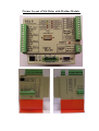
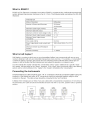
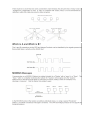
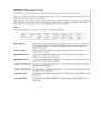
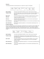
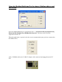
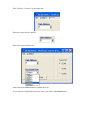
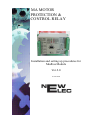
MA MOTOR
PROTECTION &
CONTROL RELAY
Installation and setting up procedures for
Modbus Module
Ver.2.0
26 June 2008
Picture Layout of MA-Relay with Modbus Module.
Description of Modbus Module Connections.
I2C Port
• Used as an engineering port to change the modules Modbus Address and baud rate.
Pin assignment:
1. VDD
2. SCL
3. SDA
4. Rx
5. Tx
6. GND
• This port can also be used with expansion modules, e.g. FLED unit.
5-Pin Modbus RTU connection.
• GND – Ground connection (Optional).
• A – Modbus High connection.
• SCRN – Cable Screen connection. (Optional).
• B – Modbus Low Connection.
• +5V – Output voltage of +5 Volt. (No connection required for Modbus).
DB9 Modbus RTU connection.
1. SCRN
2. N.C.
3. Modbus Connection A.
4. N.C.
5. GND
6. +5V
7. N.C.
8. Modbus Connection B.
9. N.C.
Using the ModbusModSetup Tool to change Modbus address and
BAUD rate
Open the ModbusModSetup.exe application in the “…\Information\Downloads\MA Relay
Downloads\Doc\Modbus Docs\ModBusMod Interface” directory on the NewElec
Application install CD.
When the application is opened, select the correct communication port you have connected to
the Modbus slave,
with a CAB0004 cable and a CAB0013 adaptor cable connected and plugged into the I2C
Port.
Then Click on “Connect” on the menu bar.
Enter the required slave address,
Select the required baud rate,
And click on the Write button to update the slave.
To read-up the configuration from the slave, just click on the Read button.