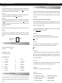
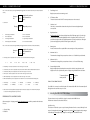
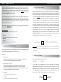
1
IMPORTANT NOTE: The output relays 2 and 3 time allocations are stored with the current I/O map. therefore
once you are satisfied with the input/output configuration and you have edited the timers it would then be
appropriate to save the I/O map to one of the memory slots (1 to 8) which would include the stored timer
settings.
3. The Load Preset Sub Menu
MA RDU - 216
Remote Display Unit
On entering this sub menu from the relay setting menu, you will be prompted by a cursor to select a stored
preset (numbered 1 to 8) with embedded I/O configuration. Navigate with the ⇐ (left) and ⇒ (right) keys to
choose a preset location. Once this has been done you could download to a connected MA relay or edit the
INSTALLATION AND SETTING UP PROCEDURE
I/O map to your liking and re-store the information in the same OR another preset slot.
On completion
press the
RESET
⇐
MENU
navigation key to
return you to the
previous menu.
4. The Download Map Sub Menu
Selection of this sub menu will automatically download the current Input/Output map with relay 2 and 3
timers settings to the connected relay.
IN CONCLUSION
This user’s guide appertains to all NewElec RDU 216 models manufactured from June 2005 onwards. Should your RDU 216 be
of an earlier version you might wish to send it to NewElec for re-programming to the latest version. Nonetheless the guide
will still serve as a general information channel for all users. The main differences between the latest versions and the earlier
models are summarized below:
*
*
*
*
*
Earth leakage sensing level permits users to se tthe threshold to as low as 50 mA.
The I/O map and associated timers are no longer treated as separate settings and are both found in the RELAY
SETTINGS menu.
The new version permits full use of digital input 5. (I.e.) Does not have to be allocated to remote reset.
The new version provides for a more powerful I/O selection as you are now able to add the logical “WHILE IN
SERVICE” function as well as allocate ALARM functions for unbalance, overloading, PTC high and under-load conditions.
The new RDU 216 permits the selection and downloading of PRESET stored values without the need for a
dongel if so desired.
REMEMBER, however, that these new functions will not work UNLESS you also upgrade your respective MA relays to Rev 10 e or
higher. If you are the owner of a new RDU 216 and need to programme an older version MA relay, this is still possible as long as
you make no attempt to use one of the new features. IF YOU DO, the RDU 216 will hang up when attempting to download.
298 Soutter Street, Pretoria West
Postnet Suite #73, Private Bag X06, Quagga, 0058
Tel: (012) 327-1729 Fax: (012) 327-1733
E-mail: [email protected] Http://www.newelec.co.za
1. Operating Instructions
OVERVIEW
The MA RDU 216 is a panel-mounted keypad entry (2 x 16 LCD) display unit which can be used as a hand-held
programming and display unit for the NewElec MA range of motor protection relays. It permits the user to set all
the protection parameters and monitor the actual values while the motor is in operation, as well as view the fault
alarms and real time clock logged faults. In order to circumvent unauthorised alterations of any given protection
relay setting parameters, the MA RDU 216 unit requires a dongel connected in line with the DB9 RS 232 serial
communication cable in order to alter any settings. Should the dongel not be present, read only functions will
be tolerated by the device. The MA RDU 216 requires a power supply of either 110 or 220 Volt a.c.
The MA RDU 216 unit measurement is 150 x 85 x 80 mm with a mass of 300 grams.
All functions in the unit are accessible via a descriptive membrane keypad while the 2 x 16 back lit LCD display
is used to indicate the menu driven requested values OR prompt the operator as to which key is to be pressed
next in the event of a multiple keystroke sequence. The latter would typically apply to extraction of trip records,
editing set values etc.
As far as memory allocation is concerned, an analogy could be considered to a PC in that the MA RDU 216 has a
RAM storage area where information could be lost if the auxiliary supply is removed BUT also has eight storage
areas for presets which are not affected by power disruptions. Favourite or frequently used settings including
the I/O map configurations chosen and timer settings can be stored in any 1 of the eight storage areas.
NAVIGATION KEYS
To move one character to the right
To move one character to the left
To move up OR increment a value
To move down OR decrement a value
The
ENTER
key is used to select a menu
OR sub-menu OR to toggle
between enable and disable
functions.
PRESS
PRESS
PRESS
PRESS
The
⇒
⇐
⇑
⇓
RESET
⇐
MENU
key is used to access the previous level of menus OR reset a
trip condition. If held down for
several seconds, it will return
you to the VERY beginning.
MA RDU - 216 REMOTE DISPLAY UNIT
On initial power up of the NewElec introductory splash screen, the MA RDU 216 will present the user with
a display of the main or initial menu consisting of five separate headings. Each of the main sections are
appropriately titled and can be selected by using the UP/DOWN navigation scrolling keys and entered into
by pressing the ENTER navigation key. When entering sub menus A and B at a later stage, the ENTER key will
toggle between ENABLE/DISABLE selection functions.
MA RDU - 216 REMOTE DISPLAY UNIT
1. Change I/O Map Sub Menu
This sub menu permits the user to select one of sixteen possible combinations which link digital inputs (1 to
4) with relay output numbers 2 and 3. For example, the first option on line 1 displays all four available digital
inputs in the low (untrue) logic positions. The top left corner displays the digital input states and are read
In order to facilitate the protection settings of multiple relays which may have different setting parameters in
association with either different applications or different kW motors, the MA RDU 216 accommodates up to 8
memory slots numbered from 1 to 8. These memory slots are useful for storing information (even when the
auxiliary power supply is removed) for the purpose of downloading of setting parameters to the appropriate
MA motor protection relays at a later time.
consecutively from right to left as digital inputs 1,2,3 and 4. Relays 2 and 3 are displayed on the bottom line
and the user can now dictate the state of these output contacts when all digital inputs are low (untrue). This
is achieved by means of the ⇐ (left) ⇒ (right) navigation keys and the enter key which will have the effect
of allocating the selected relay output (shown by an X) to operate or not operate. The following line 2> is
selected by the ⇓ navigation key. Line 2 will show digital input 1 to be high (true) and permit the operator
Any relay settings which are not stored in the MA RDU 216 memory slots will be lost if the auxiliary power
supply is removed from the unit.
MENUS AND SUB MENUS
The main and initial menu consists of FIVE categories as follows:
to once again select relay 2 OR 3 OR both to energise or not, as the case may be. There are 16 permutations
available and therefore 16 line allocations for this menu. The corresponding timers for relays 2 and 3 can be
reached and adjusted by means of the next sub menu. AFTER LINE 16 YOU MAY ALSO CHOOSE TO HAVE THE
CONFIGURATION APPLICABLE FOR MOTOR “IN SERVICE” ONLY OR ALLOCATE RELAY 3 TO ANY OF UP TO 4 PRETRIP WARNING ALARM OUTPUTS. Once the input/output configuration has been completed, it is a good idea
*
Actual Values
*
Relay Settings (only accessible on connection of the dongel)
to store the information into one of the memory slots (1 to 8) so as not to lose it.
* Fault Report
* Last Faults
* Options (only accessible on connection of the dongel)
1. Selecting the ACTUAL VALUES Menu
You would do this by pressing the
RESET
⇐
MENU
key twice and then selecting the SAVE MEMORY sub menu.
IMPORTANT NOTE: If control relay output number 2 is assigned to perform a function it will no longer perform the Minimum
Load restart output contact operation. Similarly, if relay output 3 in the I/O map is re-configured it will no longer act as a slave
This menu selection will enable the operator to READ the MA motor protection relay parameters either while
the motor is running or standing. Readable values are listed from 1 to 12.
The values are:
1. Thermal Capacity
Utilised thermal capacity expressed from 1 to 100 %. A zero is indicative of a cold motor while
100 % is indicative of a hot motor that has tripped on thermal overload.
2. Red/White And Blue Phase Currents
The currents will be displayed either as a % of full load setting or in amperes. The choice is achieved by inserting the MA relay model number. If “O” is selected a % display will occur. Alternatively, the currents will be displayed in Amp. Note that entry of the model number can only be achieved using the NewElec front-end software and a laptop.
3.
Phase Voltage
The voltage you would read between your phases.
4.
Line Voltage
The voltage you would read between phase and neutral.
to the main trip relay.
2. Edit Timers Sub Menu
When entering this sub menu you will be presented with:
1. Relay 2 Timer
2. Relay 3 Timer
Use the ⇓ (Down) and ⇑ (Up) navigation keys for your choice of output relay 2 OR 3 and then the
ENTER navigation key. This will bring up a further sub menu that will permit you to allocate a time interval
ranging from 0 seconds up to a maximum of 50 minutes for each timer / relay configuration. Use the ⇐ (left)
and ⇒ (right) navigation keys to bring the cursor to the minutes OR seconds display and adjust your time
allocations by using the ⇑ (Up) OR ⇓ (Down) navigation keys to alter the values respectively.
Finish by
pressing the
RESET
⇐
MENU
key to return to the
previous menu.
MA RDU - 216 REMOTE DISPLAY UNIT
Note: For the above selection, pressing the ENTER key will toggle between the alternatives of either (auto / manual) OR (enable/
disable).
Now press
the
RESET
⇐
MENU
navigation key and move
1 line downwards to
get to:
Pressing
ENTER
will permit you to set:
7. Sub menu B
1.
Earth Leakage enable/disable
2.
PTC 1 enable/disable
3. PTC 2 enable/disable
4.
PTC 3 enable/disable
5. Overvoltage enable/disable
6.
Single Phasing enable/disable
7. Earth Leakage Filter enable/disable
8.
Short Circuit enable/disable
Note: For the above selection pressing the ENTER key will toggle between the alternatives of either (enable/disable).
Now press
the
RESET
⇐
MENU
navigation key and move
1 line downwards to
get to:
MA RDU - 216 REMOTE DISPLAY UNIT
5. Earth Leakage Level
Displays any measured current running to earth.
6. PTC Resistance Value
The actual resistance value of the PTC over temperature sensors when connected.
7. Unbalance Level
Shows the % current unbalance between the three phase load currents being drawn by the
connected load.
8. Digital Input Status
Read from right to left. This indicates the digital state of the 5 field input signals. A (1) at the right most position would indicate that digital input number 1 is high (true) while a (0) in the second position from the right would refer to digital input number 2 as being low (untrue) etc. Although 8 positions are displayed only the first 5 from the right are actually used.
9.
Running Hours
Provides an indication of the completed full in service running hours of the protected motor.
10.
Maximum Load Set
The maximum load setting for the protected motor shown as a % of the MA relay model number.
8. Line Voltage - You are expected to enter a value from 0 to 3 in accordance with the following table:
0 = 0
Volt
1 = 110
Volt
2 = 380
Volt
3 = 525
Volt
9. PTC Trip Delay - You are expected to enter a value in the range 1 to 10 seconds.
10. Unbalance Trip Level - You are expected to set the phase current unbalance detection threshold between 5 to 50 %
11. Unbalance Trip Delay - You are expected to enter a value in the range 1 to 10 seconds.
11. Minimum Load Set
The minimum load setting for the protected motor shown as a % of motor full load setting.
12. Protection Relay Model No
Displays the MA relay model number that in turn enables or disables % amp indication on the
display unit. This can only be altered by means of a laptop using the NewElec front end software.
12. PTC Trip Level - You are expected to enter a value in ohms in the range 100 to 5100 Ohms.
To return to the main
menu press the
13. Min Load Trip Delay - You are expected to enter a value in the range 1 to 10 seconds.
14. Min Load Restart Delay - You are expected to enter a value from 0 to 9 in accordance with the following table:
0 = Manual only
5 = 30 Minutes
1 = 10 seconds
6 = 45 Minutes
2 = 5 Minutes
7 = 1 Hour
3 = 10 Minutes
8 = 3 Hours
4 = 20 Minutes
9 = 6 Hours
15. Reset Control - The factory default selects digital input 5 for remote reset purposes. This menu item will permit you
to cancel this and free digital input 5 for your own use.
EXPANDING ON THE I/O MAPPING SUB MENU
When entering the I / O Mapping menu (from the relay setting menu), you will be presented with 2 sub menus.
These are:
1. Change I/O Map
2. Edit timers
RESET
⇐
MENU
navigation
key.
FINAL NOTE CONCERNING THE ABOVE
If your RDU 316 is connected to an MA relay and is left un-attended, the RDU 216 will automatically scroll
through the twelve actual values every 10 seconds.
2. Selecting the RELAY SETTINGS Menu
This menu selection is only accessible if the dongel is connected to the MA RDU 216 unit.
FIVE sub menu selections become available. These are:
Upload from relay
This selection will allow the operator to upload setting information from the connected MA relay for the
purpose of viewing that relay’s settings OR editing that relay’s settings OR downloading that relay’s settings to
another MA relay OR storing that relay’s settings into a memory preset on the MA RDU 216 unit.
MA RDU - 216 REMOTE DISPLAY UNIT
Download to relay
This selection will permit the operator to download setting parameters currently in the MA RDU 216 to be
transmitted to the connected MA relay. This could be temporary stored settings (i.e. not from a memory preset)
OR from a preset slot. It could also take the form of edited settings.
Load Preset
This selection permits setting parameters presently stored in one of the memory slots numbered from 1 to 8
for the purpose of downloading to a connected MA relay OR for editing purposes.
Edit Memory
This selection permits the editing of setting parameters stored in one of the memory slots numbered from 1
to 8 OR entering new setting parameters for later storing into one of the memory slots OR downloading to a
connected MA relay without necessarily storing the information into one of the memory slots. Refer pages 6
and 7 for an expanded explanation.
Save Memory
This selection permits the storage of existing setting parameters to one of the memory slots numbered from
1 to 8.
I/O Mapping
This provides the user access to the digital input map and related output relays number 2 and 3 as well as
associated timers. Note that allocation of functions to output relays 2 and 3 will override any factory default
settings.
RESET
⇐
MENU
To return to the main
menu press the
navigation
key.
MA RDU - 216 REMOTE DISPLAY UNIT
5. Selecting the OPTIONS Menu
The factory default setting will not permit you to enter this menu without a supporting dongel. The selection
will permit you to select a stored memory preset setting for downloading to an MA relay without the
subsequent requirment for a dongel. However uploading and editing functions will continue to require the
security dongel.
EXPANDING ON THE RELAY SETTINGS EDIT MEMORY SUB MENU
When entering the EDIT MEMORY sub-menu, the following relay setting-up parameters will be encountered.
This review is intended to explain the settings, range of values and purpose for the settings. The same
navigation keys mentioned earlier will be used.
On entering the RELAY SETTINGS sub-menu, EDIT MEMORY (accessible only by means of a dongel) the
following setting parameters will require your attention:
1. Max Load Set
You are expected to enter a % Maximum load setting in the range 10 to 100 %.
Example: You have a MA 250 relay and the full motor load current is 120 Amp. The setting would then be
120 x 100 i.e. 48 %.
250
2. Min Load Set
3. Selecting the FAULT REPORT Menu
You are expected to enter a minimum % load setting in the range of 20 to 100% of the full load setting.
Example: From the previous step, the minimum load is 75 Amp. Therefore the setting would be
75 i.e. 62 %.
120
This menu selection permits the operator to view:
1. Alarm flags
2. Trip flags
3. Thermal Curve
A (0) value indicates a non event.
A (1) value indicates an occurrence.
You are expected to enter the correct cold thermal curve class for the protected motor. As a guide line refer to
pages 44 and 45 of the NewElec main catalogue (the yellow highlighted columns). The setting range is from 5
to 35 seconds. Considering the full load capability of the motor used in the above examples, a thermal curve
KEY TO ABREVIATIONS USED
Uv of 20 seconds could be adequate.
= Undervoltage Is = In Service
El = Earth Leakage Fc = Frozen contactor
Uc
= Undercurrent
Ov
=
Overvoltage
Sp
= Single Phasing
R3
=
RTD Input No 3
Ub
= Unbalance
R2
=
RTD Input No 2
Rs
= Running Stall
R1
=
RTD Input No 1
Oc
= Overcurrent
Pr
=
Phase Rotation
4. Selecting the LAST FAULTS Menu
This menu selection will access a list of the last 4 faults stored in the connected MA motor protection relay
memory. The faults are time and date stamped with the most recent fault shown first. The fault type is also
indicated.
4. EL Trip Level
You are expected to enter the earth leakage detection level in the range 50 to 1000 mA. When starting large
motors by DOL method you may expect nuisance trips if this setting is set below 250 mA.
5. EL Trip Delay
You are expected to enter a value ranging from 100 to 1000 milli seconds.
6. Sub menu A
Pressing enter will permit you to set:
1)
Auto/Manual reset for overload trips
3)
Minimum load auto reset enable/disable
5)
Relay Fail Safe enable/disable
7)
Phase Rotation enable/disable
2)
4)
6)
8)
Minimum load function enable/disable
Undervoltage enable/disable
Unbalance enable/disable
Running Stall enable/disable
MA RDU - 216 REMOTE DISPLAY UNIT
Note: For the above selection, pressing the ENTER key will toggle between the alternatives of either (auto / manual) OR (enable/
disable).
Now press
the
RESET
⇐
MENU
navigation key and move
1 line downwards to
get to:
Pressing
ENTER
will permit you to set:
7. Sub menu B
1.
Earth Leakage enable/disable
2.
PTC 1 enable/disable
3. PTC 2 enable/disable
4.
PTC 3 enable/disable
5. Overvoltage enable/disable
6.
Single Phasing enable/disable
7. Earth Leakage Filter enable/disable
8.
Short Circuit enable/disable
Note: For the above selection pressing the ENTER key will toggle between the alternatives of either (enable/disable).
Now press
the
RESET
⇐
MENU
navigation key and move
1 line downwards to
get to:
MA RDU - 216 REMOTE DISPLAY UNIT
5. Earth Leakage Level
Displays any measured current running to earth.
6. PTC Resistance Value
The actual resistance value of the PTC over temperature sensors when connected.
7. Unbalance Level
Shows the % current unbalance between the three phase load currents being drawn by the
connected load.
8. Digital Input Status
Read from right to left. This indicates the digital state of the 5 field input signals. A (1) at the right most position would indicate that digital input number 1 is high (true) while a (0) in the second position from the right would refer to digital input number 2 as being low (untrue) etc. Although 8 positions are displayed only the first 5 from the right are actually used.
9.
Running Hours
Provides an indication of the completed full in service running hours of the protected motor.
10.
Maximum Load Set
The maximum load setting for the protected motor shown as a % of the MA relay model number.
8. Line Voltage - You are expected to enter a value from 0 to 3 in accordance with the following table:
0 = 0
Volt
1 = 110
Volt
2 = 380
Volt
3 = 525
Volt
9. PTC Trip Delay - You are expected to enter a value in the range 1 to 10 seconds.
10. Unbalance Trip Level - You are expected to set the phase current unbalance detection threshold between 5 to 50 %
11. Unbalance Trip Delay - You are expected to enter a value in the range 1 to 10 seconds.
11. Minimum Load Set
The minimum load setting for the protected motor shown as a % of motor full load setting.
12. Protection Relay Model No
Displays the MA relay model number that in turn enables or disables % amp indication on the
display unit. This can only be altered by means of a laptop using the NewElec front end software.
12. PTC Trip Level - You are expected to enter a value in ohms in the range 100 to 5100 Ohms.
To return to the main
menu press the
13. Min Load Trip Delay - You are expected to enter a value in the range 1 to 10 seconds.
14. Min Load Restart Delay - You are expected to enter a value from 0 to 9 in accordance with the following table:
0 = Manual only
5 = 30 Minutes
1 = 10 seconds
6 = 45 Minutes
2 = 5 Minutes
7 = 1 Hour
3 = 10 Minutes
8 = 3 Hours
4 = 20 Minutes
9 = 6 Hours
15. Reset Control - The factory default selects digital input 5 for remote reset purposes. This menu item will permit you
to cancel this and free digital input 5 for your own use.
EXPANDING ON THE I/O MAPPING SUB MENU
When entering the I / O Mapping menu (from the relay setting menu), you will be presented with 2 sub menus.
These are:
1. Change I/O Map
2. Edit timers
RESET
⇐
MENU
navigation
key.
FINAL NOTE CONCERNING THE ABOVE
If your RDU 316 is connected to an MA relay and is left un-attended, the RDU 216 will automatically scroll
through the twelve actual values every 10 seconds.
2. Selecting the RELAY SETTINGS Menu
This menu selection is only accessible if the dongel is connected to the MA RDU 216 unit.
FIVE sub menu selections become available. These are:
Upload from relay
This selection will allow the operator to upload setting information from the connected MA relay for the
purpose of viewing that relay’s settings OR editing that relay’s settings OR downloading that relay’s settings to
another MA relay OR storing that relay’s settings into a memory preset on the MA RDU 216 unit.
MA RDU - 216 REMOTE DISPLAY UNIT
On initial power up of the NewElec introductory splash screen, the MA RDU 216 will present the user with
a display of the main or initial menu consisting of five separate headings. Each of the main sections are
appropriately titled and can be selected by using the UP/DOWN navigation scrolling keys and entered into
by pressing the ENTER navigation key. When entering sub menus A and B at a later stage, the ENTER key will
toggle between ENABLE/DISABLE selection functions.
MA RDU - 216 REMOTE DISPLAY UNIT
1. Change I/O Map Sub Menu
This sub menu permits the user to select one of sixteen possible combinations which link digital inputs (1 to
4) with relay output numbers 2 and 3. For example, the first option on line 1 displays all four available digital
inputs in the low (untrue) logic positions. The top left corner displays the digital input states and are read
In order to facilitate the protection settings of multiple relays which may have different setting parameters in
association with either different applications or different kW motors, the MA RDU 216 accommodates up to 8
memory slots numbered from 1 to 8. These memory slots are useful for storing information (even when the
auxiliary power supply is removed) for the purpose of downloading of setting parameters to the appropriate
MA motor protection relays at a later time.
consecutively from right to left as digital inputs 1,2,3 and 4. Relays 2 and 3 are displayed on the bottom line
and the user can now dictate the state of these output contacts when all digital inputs are low (untrue). This
is achieved by means of the ⇐ (left) ⇒ (right) navigation keys and the enter key which will have the effect
of allocating the selected relay output (shown by an X) to operate or not operate. The following line 2> is
selected by the ⇓ navigation key. Line 2 will show digital input 1 to be high (true) and permit the operator
Any relay settings which are not stored in the MA RDU 216 memory slots will be lost if the auxiliary power
supply is removed from the unit.
MENUS AND SUB MENUS
The main and initial menu consists of FIVE categories as follows:
to once again select relay 2 OR 3 OR both to energise or not, as the case may be. There are 16 permutations
available and therefore 16 line allocations for this menu. The corresponding timers for relays 2 and 3 can be
reached and adjusted by means of the next sub menu. AFTER LINE 16 YOU MAY ALSO CHOOSE TO HAVE THE
CONFIGURATION APPLICABLE FOR MOTOR “IN SERVICE” ONLY OR ALLOCATE RELAY 3 TO ANY OF UP TO 4 PRETRIP WARNING ALARM OUTPUTS. Once the input/output configuration has been completed, it is a good idea
*
Actual Values
*
Relay Settings (only accessible on connection of the dongel)
to store the information into one of the memory slots (1 to 8) so as not to lose it.
* Fault Report
* Last Faults
* Options (only accessible on connection of the dongel)
1. Selecting the ACTUAL VALUES Menu
You would do this by pressing the
RESET
⇐
MENU
key twice and then selecting the SAVE MEMORY sub menu.
IMPORTANT NOTE: If control relay output number 2 is assigned to perform a function it will no longer perform the Minimum
Load restart output contact operation. Similarly, if relay output 3 in the I/O map is re-configured it will no longer act as a slave
This menu selection will enable the operator to READ the MA motor protection relay parameters either while
the motor is running or standing. Readable values are listed from 1 to 12.
The values are:
1. Thermal Capacity
Utilised thermal capacity expressed from 1 to 100 %. A zero is indicative of a cold motor while
100 % is indicative of a hot motor that has tripped on thermal overload.
2. Red/White And Blue Phase Currents
The currents will be displayed either as a % of full load setting or in amperes. The choice is achieved by inserting the MA relay model number. If “O” is selected a % display will occur. Alternatively, the currents will be displayed in Amp. Note that entry of the model number can only be achieved using the NewElec front-end software and a laptop.
3.
Phase Voltage
The voltage you would read between your phases.
4.
Line Voltage
The voltage you would read between phase and neutral.
to the main trip relay.
2. Edit Timers Sub Menu
When entering this sub menu you will be presented with:
1. Relay 2 Timer
2. Relay 3 Timer
Use the ⇓ (Down) and ⇑ (Up) navigation keys for your choice of output relay 2 OR 3 and then the
ENTER navigation key. This will bring up a further sub menu that will permit you to allocate a time interval
ranging from 0 seconds up to a maximum of 50 minutes for each timer / relay configuration. Use the ⇐ (left)
and ⇒ (right) navigation keys to bring the cursor to the minutes OR seconds display and adjust your time
allocations by using the ⇑ (Up) OR ⇓ (Down) navigation keys to alter the values respectively.
Finish by
pressing the
RESET
⇐
MENU
key to return to the
previous menu.
IMPORTANT NOTE: The output relays 2 and 3 time allocations are stored with the current I/O map. therefore
once you are satisfied with the input/output configuration and you have edited the timers it would then be
appropriate to save the I/O map to one of the memory slots (1 to 8) which would include the stored timer
settings.
3. The Load Preset Sub Menu
MA RDU - 216
Remote Display Unit
On entering this sub menu from the relay setting menu, you will be prompted by a cursor to select a stored
preset (numbered 1 to 8) with embedded I/O configuration. Navigate with the ⇐ (left) and ⇒ (right) keys to
choose a preset location. Once this has been done you could download to a connected MA relay or edit the
INSTALLATION AND SETTING UP PROCEDURE
I/O map to your liking and re-store the information in the same OR another preset slot.
On completion
press the
RESET
⇐
MENU
navigation key to
return you to the
previous menu.
4. The Download Map Sub Menu
Selection of this sub menu will automatically download the current Input/Output map with relay 2 and 3
timers settings to the connected relay.
IN CONCLUSION
This user’s guide appertains to all NewElec RDU 216 models manufactured from June 2005 onwards. Should your RDU 216 be
of an earlier version you might wish to send it to NewElec for re-programming to the latest version. Nonetheless the guide
will still serve as a general information channel for all users. The main differences between the latest versions and the earlier
models are summarized below:
*
*
*
*
*
Earth leakage sensing level permits users to se tthe threshold to as low as 50 mA.
The I/O map and associated timers are no longer treated as separate settings and are both found in the RELAY
SETTINGS menu.
The new version permits full use of digital input 5. (I.e.) Does not have to be allocated to remote reset.
The new version provides for a more powerful I/O selection as you are now able to add the logical “WHILE IN
SERVICE” function as well as allocate ALARM functions for unbalance, overloading, PTC high and under-load conditions.
The new RDU 216 permits the selection and downloading of PRESET stored values without the need for a
dongel if so desired.
REMEMBER, however, that these new functions will not work UNLESS you also upgrade your respective MA relays to Rev 10 e or
higher. If you are the owner of a new RDU 216 and need to programme an older version MA relay, this is still possible as long as
you make no attempt to use one of the new features. IF YOU DO, the RDU 216 will hang up when attempting to download.
298 Soutter Street, Pretoria West
Postnet Suite #73, Private Bag X06, Quagga, 0058
Tel: (012) 327-1729 Fax: (012) 327-1733
E-mail: [email protected] Http://www.newelec.co.za
1. Operating Instructions
OVERVIEW
The MA RDU 216 is a panel-mounted keypad entry (2 x 16 LCD) display unit which can be used as a hand-held
programming and display unit for the NewElec MA range of motor protection relays. It permits the user to set all
the protection parameters and monitor the actual values while the motor is in operation, as well as view the fault
alarms and real time clock logged faults. In order to circumvent unauthorised alterations of any given protection
relay setting parameters, the MA RDU 216 unit requires a dongel connected in line with the DB9 RS 232 serial
communication cable in order to alter any settings. Should the dongel not be present, read only functions will
be tolerated by the device. The MA RDU 216 requires a power supply of either 110 or 220 Volt a.c.
The MA RDU 216 unit measurement is 150 x 85 x 80 mm with a mass of 300 grams.
All functions in the unit are accessible via a descriptive membrane keypad while the 2 x 16 back lit LCD display
is used to indicate the menu driven requested values OR prompt the operator as to which key is to be pressed
next in the event of a multiple keystroke sequence. The latter would typically apply to extraction of trip records,
editing set values etc.
As far as memory allocation is concerned, an analogy could be considered to a PC in that the MA RDU 216 has a
RAM storage area where information could be lost if the auxiliary supply is removed BUT also has eight storage
areas for presets which are not affected by power disruptions. Favourite or frequently used settings including
the I/O map configurations chosen and timer settings can be stored in any 1 of the eight storage areas.
NAVIGATION KEYS
To move one character to the right
To move one character to the left
To move up OR increment a value
To move down OR decrement a value
The
ENTER
key is used to select a menu
OR sub-menu OR to toggle
between enable and disable
functions.
PRESS
PRESS
PRESS
PRESS
The
⇒
⇐
⇑
⇓
RESET
⇐
MENU
key is used to access the previous level of menus OR reset a
trip condition. If held down for
several seconds, it will return
you to the VERY beginning.