1
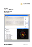
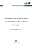
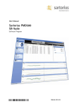
Lumencor
SPECTRA Light Engine ®
Instruction Manual
Lumencor, Inc. 14964 NW Greenbrier Parkway, Beaverton, OR 97006
T 503.213.4269 F 503.536.6741
www.lumencor.com
Emissions Certifications
This equipment has been tested and found to comply with the limits of EMC directive 2004/108/EC. These limits are
designed to provide reasonable protection against harmful interference when the equipment is operated in a commercial
environment. This equipment generates, uses, and can radiate radio frequency energy and, if not installed and used in
accordance with the instruction manual, may cause harmful interference to radio communications.
Safety Certifications
2006/95/EC
CB Scheme
CE Declaration of Conformity
TUV NRTL Listing
TUV Canadian Listing
TUV European License
SPECTRA, SPECTRA S and SPECTRA X Instruction Manual
1
Table of Contents
1 Introduction
2 Precautions and Warnings
3
Installation and Operating Instructions
4
Spectral Output
5
Routine Maintenance and Trouble Shooting
6
Customer Support
7
Product Specifications
8
Connectors
9
Declaration of Conformance
10 Warranty
SPECTRA, SPECTRA S and SPECTRA X Instruction Manual
2
1. Introduction
The Lumencor SPECTRA family of light engines (SPECTRA, SPECTRA S and SPECTRAX) are designed for laboratory
use by bioanalytical researchers and/or developers of life science instrumentation. The SPECTRA (all models) provides 3,
4, 5, 6 or 7 spectrally discrete, bright, controllable light outputs directly to a sample; or in the case of fluorescence
microscopy, to the objective. Each of the colors is produced by an independent module that has been optimized to
produce a precise set of wavelengths.
This manual covers all SPECTRA models: SPECTRA X-YYY-ZZ or SPECTRAX X-YYY-ZZ. X denotes the number of
colors, YYY denotes a unique customer code and ZZ denotes option and revision. The first Z variable indicates a
standard SPECTRA if it is blank or a color mix or simultaneous output SPECTRA (or SPECTRA X) if it is an “S”. The
second Z denotes the revision level. Any reference to “SPECTRA” in this manual shall apply to all SPECTRA models
unless noted otherwise.
The light sources within the SPECTRA are controlled by software; either via a serial interface (RS-232 or USB) to a
computer running a Lumencor supplied GUI or via a TTL interface to a computer running a third party microscopy
software application.The user can enable or disable each source independently and change the intensity of each source
independently. The only manual control is a power switch on the rear panel to turn on/off the power into the unit. A green
power indicator on the rear cover is lit (“ON”) when the power supply is connected to the SPECTRA and the power
switch is in the on position.
2. Precautions and Warnings
A few simple practices will ensure trouble-free operation for the life of the light engine.
Safety Instructions:
Please read and follow all safety instructions provided BEFORE using your new SPECTRA. Failure to comply with the
safety instructions may result in fire, electrical shock, or personal injury and may damage or impair protection provided by
equipment. Please save all safety instructions.
Safety Definitions:
Warning: Statements identify conditions or practices that could result in personal injury.
Caution: Statements identify conditions or practices that could result in damage to your equipment.
Safety Items:
Warning: DO NOT use an unapproved power supply. The Lumencor supplied external power supply is
recommended for use with the SPECTRA light engines. Alternate 24VDC/5A power supplies may be used for the
standard SPECTRA (no simultaneous outputs) or alternate 28-30VDC/7.9A power supplies may be used for SPECTRA
X and SPECTRA S (simultaneous outputs) but it is imperative that it has output over-current protection, as the power
input of the SPECTRA is not fused. Connect the AC power cord to a receptacle with a protective safety (earth) ground
terminal.
SPECTRA, SPECTRA S and SPECTRA X Instruction Manual
3
Warning: DO NOT stare into the output of the light engine. The brightness of this light source is higher than most
commercial lighting fixtures and is intended to couple directly into a microscope or other bioanalytjcal instrument.
Caution: DO NOT open the unit. There are no serviceable parts inside and opening the light engine enclosure will void
the manufacturer’s warranty.
Caution: DO NOT connect a video cable to the TTL input enable port. Although the connector might look
compatible, this input is not intended to be driven by a video signal.
Caution: DO NOT set liquids on the light engine. Spilled liquids may damage your light engine.
Caution: DO NOT drop the light engine. It contains glass optical components that could be damaged or misaligned
by the shock produced by a drop onto a hard surface.
DISCLAIMER: Lumencor shall not be liable for injury to the user or damage to the product resulting from the
SPECTRA being used in a way for which it was not intended and in complete disregard for all posted safety
precautions and warnings.
3. Installation and Operating Instructions
The SPECTRA family of light engines all ship with the following list of standard components.
1.
SPECTRA light engine, configured with five, six or seven channels (colors). The particular excitation filter
configuration within the unit will be noted on a label affixed to the bottom of the unit.
2.
A 24V/5A power supply (Lumencor part no. 27-10002) ships with SPECTRA X-YYY- Z and a 28V/7.9A power
supply (Lumencor part no. 27-10003) ships with SPECTRA X-YYY-SZ.
3.
A 6ft AC power cord for the power supply (for North American customers, Lumencor part no. 29-10002, for UK
customers, Lumencor part no. 29-10004 and for European customers, Lumencor part no. 29-10005).
4.
A USB-to-RS232 cable (Lumencor part no. 29-10011).
SPECTRA ships with one output adapter included with the unit. The user may choose from one of the following.
Output Adaptor
Lumencor Part No.
Liquid Light Guide
82-10012
Nikon TI
82-10011
Olympus IX71/81
82-10010
Zeiss x00M
82-10009
Fly-In
82-10013
1mm Quartz Fiber
82-10015
SPECTRA, SPECTRA S and SPECTRA X Instruction Manual
4
The SPECTRA X has a feature that other SPECTRAs in the family do not; removable optical excitation filters. There are
fixed in the SPECTRA and SPECTRA S. The filters are installed in individual holders which the user can access once the
top cover retained by two thumb screws is removed. Refer to the photo below.
SPECTRA X with removable filter holders
SPECTRA, SPECTRA S and SPECTRA X Instruction Manual
5
When setting the SPECTRA up for use, be sure to place the unit on a hard surface and avoid blocking or restricting
airflow at the air inlets or exhaust ports on the enclosure. Restricting the airflow will cause the unit to operate at elevated
temperatures and will result in decreased product life and/or premature failure.
Position the unit in such an orientation that allows unrestricted access to the DC power connector. In an emergency, you
may need to disconnect power to the unit quickly.
The SPECTRA can either be controlled by a Lumencor supplied GUI via a RS-232 port, by the Lumencor Remote
Control Accessory (RCA) via the RS-232 port or by a 3rd party laboratory software program via the TTL port. The GUI
provides a quick and easy way to control your new light engine. You will have the ability to turn each source within the
unit on/off, adjust the power of each source independently from off to full power, switch between the GREEN and
YELLOW excitation filters and also cycle through all sources automatically at a frequency chosen by the user. Refer to
the photo below of the rear panel for the location of the various connectors.
Rear Panel of SPECTRA light engine
SPECTRA, SPECTRA S and SPECTRA X Instruction Manual
6
3.1 GUI Installations
Installation instructions follow for GUI control of the SPECTRA. Connectivity between the computer and your
SPECTRA can be accomplished one of two ways; either using a RS-232 straight-thru cable or using the optional
USB-to-RS232 adapter cable. Both methods are covered below.
GUI Installation and Operating Instructions (using RS-232 straight-thru cable)
Download the zip file for the SPECTRA GUI from http://www.lumencor.com/software_control.html.
Unzip the file and run setup.exe to install the SPECTRA GUI.
Connect the RS-232 cable between the PC and the SPECTRA.
Connect the power supply to the SPECTRA.
Toggle the power switch on the rear panel to the ON “1” position. The green LED next to the switch should light.
Run the GUI by going to the Program Menu and selecting LLE Controller.
In the GUI, select “COMPUTER” mode.
In the COM pulldown menu, select the COM port assigned to serial communications. Generally this is COM1. [If
you are unsure which one that is then go to Control Panel, then System, then the Hardware tab. Select Device
Manager to see the hardware profile. Expand “PORTS (COM & LPT)” to see which COM port is assigned to the
“Communications Port” and select that port in the GUI.] The PC should now have control of each color channel in
the SPECTRA. You will have the ability to turn each color ON or OFF and adjust the intensity of each individually.
THIS STEP IS REQUIRED TO RE-ESTABLISH THE COMMUNICATION LINK WHENEVER THE SPECTRA LIGHT
ENGINE IS POWER CYCLED OR WHENEVER THE GUI IS STARTED.
GUI Installation and Operating Instructions (using USB-to-RS232 cable)
Download the zip file for the SPECTRA GUI from http://www.lumencor.com/software_control.html.
Unzip the file and run setup.exe to install the SPECTRA GUI.
Connect the USB-to-RS-232 cable between the PC and the SPECTRA.
Connect the power supply to the SPECTRA.
Toggle the power switch on the rear panel to the ON “1” position. The green LED next to the switch should light.
Run the GUI by going to the Program Menu and selecting LLE Controller.
In the GUI, select “COMPUTER” mode.
In the COM pulldown menu, select the COM port assigned to USB-to-Serial communications. [If you are unsure
which one is correct then go to Control Panel, then System, then the Hardware tab. Select Device Manager to see
the hardware profile. Expand “PORTS (COM & LPT)” to see which COM port is assigned to the “USB-to-Serial
Comm Port” and select that port in the GUI.] The PC should now have control of each color channel in the
SPECTRA, SPECTRA S and SPECTRA X Instruction Manual
7
SPECTRA. You will have the ability to turn each color ON or OFF and adjust the intensity of each individually. THIS
STEP IS REQUIRED TO RE-ESTABLISH THE COMMUNICATION LINK WHENEVER THE SPECTRA LIGHT
ENGINE IS POWER CYCLED OR WHENEVER THE GUI IS STARTED.
3.2 TTL Interface
The purpose of the TTL Interface is to provide the end-user with a more predictable means (in terms of timing) of
enabling/disabling each individual light source in the LE. This is accomplished via the parallel port on a PC. Merely
Connect the Lumencor supplied TTL cable between the PC and the TTL port on the rear of the SPECTRA. The
integration and set up of the 3rd party laboratory software is very application specific and beyond the scope of this
document. For programming information, visit the Lumencor website at http://www.lumencor.com/
software_control.html and download the SPECTRA TTL Interface Specification. Contact support if you need more
assistance.
3.3 Monitor Connector (Dosimeter)
This connector provides a means for monitoring the output of the internal Dosimeter that is measuring the relative
power output of the selected light source in the unit. The connector accepts a standard BNC connector. Lumencor
does not supply a cable.
SPECTRA, SPECTRA S and SPECTRA X Instruction Manual
8
4. Spectral Output
The spectra of the most commonly requested light engine outputs (colored bands) are shown below along with a 75W
Xenon trace (grey) and a 120W metal halide lamp output (brown). Other outputs are available upon request.
30
Relative Spectral Power (mW/nm)
25
20
15
10
5
0
350
400
450
500
550
600
650
700
Wavelength (nm)
5. Routine Maintenance and Trouble Shooting
Remove any built-up dust or accumulation on the air intake ports. A vacuum may be used to remove debris so that a
steady supply of air is available for cooling. It is recommended that these dust-filters be cleaned by a gentle suction
device at least every 6 months and more often in dusty or smoke-filled environments.
There are no user-replaceable components or sub-assemblies in SPECTRA.
6. Customer Support
T: 503.505.6985
E: [email protected]
W: http://www.lumencor.com/support/software_control
M: Lumencor, Inc., 14964 NW Greenbrier Parkway, Beaverton, OR 97006 U.S.A.
SPECTRA, SPECTRA S and SPECTRA X Instruction Manual
9
7. Product Specifications
The SPECTRA must be operated and stored within the environmental conditions specified.
Specification
Detail
Temperature
Operating
32 to 95° F (0 to 35° C)
Non-operating
-4 to 158° F (-20 to 70° C)
Humidity
Operating and non-operating
0 to 80% relative humidity, non-condensing
Altitude
Operating
0 to 10,000 feet (3,048 meters)
Non-operating
0 to 20,000 feet (6,096 meters)
Dimensions (LxWxH)
11.0 x 7.0 x 4.0 in / 27.9 x 17.8 x 10.2 cm
Weight
9 lb / 4.1 kg
Lifetime
> 10,000 hr
Input Power Requirements
24VDC / 5A (SPECTRA X-YYY- Z), 28-30VDC / 7.9A (SPECTRA X-YYY-SZ or
SPECTRAX X-YYY-SZ)
Warm-up Period
Less than 1 minute
Protection
IP Rating of X0
Sound Level
Sound Level at 1 meter < 65db(A)
Connectivity
RS-232, USB, TTL
Warranty
36 months parts and labor
SPECTRA, SPECTRA S and SPECTRA X Instruction Manual
10
8. Connectors
8.1 TTL Input Connector
This connector is used to enable/disable each source and select between the GRN/YEL excitation filter.
Pins
Definition
1, 2, 3, 11, 12, 13
Red, Green, Cyan, Teal, Blue, UV
respectively - low true enables
15 - Green/Yellow
Excitation Filter Select,
Vin = H => Green, Vin = L => Yellow
6, 7, 8, 10
Gnd
4, 9, 14
N/C
DC Characteristics
VCC = 5.0V,
Vilow (max) = 1.5V, Vihigh (min) = 3.3V,
Iilow = 0.5mA, Iihigh = 1.0μA
VCC = 5.0V,
Vilow (max) = 1.5V, Vihigh (min) = 3.3V,
Iilow = 0.5mA, Iihigh = 1.0μA
DB15HD connector Pin Definitions
8.2 RS-232 Connector
This port conforms to standard RS-232 Interface Protocol.
Pins
Definition
DC Characteristics
1, 2, 3, 4, 6, 7, 8
DCD, RXD, TXD, DTR, D3R, RTS,
CTS
VCC = 5.0V,
Vilow (max) = 0.8V, Vihigh (min) = 2.4V,
Iilow = 0.5mA, Iihigh = 1.0μA
5
Gnd
9
N/C
DB9 Connector Pin Definitions
8.3 Dosimeter Connector (Monitor)
This connector is a standard BNC connector located on the rear panel. It is used to read the internal dosimeter
by connecting to a scope or frequency counter. It outputs a square wave, 0-5V, frequency is proportional to the
power of the light being measured.
SPECTRA, SPECTRA S and SPECTRA X Instruction Manual
11
9. Declaration of Conformance
Manufacturer: Lumencor, Inc.
14964 NW Greenbrier Parkway, Beaverton, OR 97006 USA
We declare under our sole responsibility that the SPECTRA Light Engine conforms to the following directives and norms:
EMC directive 2004/108/EC
2006/95/EC
CB Scheme
CE Declaration of Conformity
TUV NRTL Listing
TUV Canadian Listing
TUV European License
10. Warranty
The SPECTRA family of light engines is backed by a 36 month warranty.
SPECTRA, SPECTRA S and SPECTRA X Instruction Manual
12