1
TVAC80020B
User guide
Version 08/2012
Original user guide in English.
Retain for future reference!
1
English
Introduction
Dear customer,
Thank you for purchasing this product.
This product complies with current domestic and European regulations. Conformity has been verified,
and all related certifications and documents are available from the manufacturer on request
(www.abus-sc.com).
To ensure this condition is maintained and that safe operation is guaranteed, it is your obligation to observe
these operating instructions!
Read the entire user guide carefully before starting operation of the product, and pay attention to all operating
instructions and safety information!
All company names and product descriptions are trademarks of the corresponding owner. All rights
reserved.
In the event of questions, please contact your local maintenance specialist or dealer.
Warning as required by §201 StGB (German Criminal Code):
Whosoever unlawfully makes an audio recording of the privately spoken words of another; or uses, or makes
a recording thus produced accessible to a third party, shall be liable to imprisonment or a fine.
Whosoever unlawfully overhears with an eavesdropping device the privately spoken words of another not
intended for his attention; or publicly communicates, verbatim or the essential content of, the privately spoken
words of another, recorded or overheard, shall incur the same penalty.
Disclaimer
This user guide has been produced with the greatest of care. Should you discover any missing information or
inaccuracies, please contact us under the address shown on the back of the manual.
ABUS Security-Center GmbH does not accept any liability for technical and typographical errors, and
reserves the right to make changes to the product and user guide at any time and without prior warning.
ABUS Security-Center GmbH is not liable or responsible for direct or indirect damage resulting from the
equipment, performance and use of this product. No forms of guarantee are accepted for the contents of this
document.
2
English
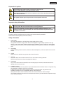
Explanation of symbols
The triangular high voltage symbol is used to warn of the risk of
injury or health hazards (e.g. caused by electric shock).
The triangular warning symbol indicates important notes in these operating instructions
which must be observed.
This symbol indicates special tips and notes on the operation of the unit.
Important safety information
All guarantee claims are invalid in the event of damage caused by non-compliance with
this user guide. We cannot be held liable for resulting damages.
In the event of material or personal damage caused by improper operation or noncompliance with the safety information, we cannot be held liable. All guarantee claims
are voided in such cases.
This device has been manufactured in accordance with international safety standards.
Please read the following safety instructions carefully.
Safety information
1.
Power supply
100 - 240 V AC voltage, 50 - 60 Hz (using a power supply unit for 5 V DC)
Only operate this device using a power source which supplies the grid voltage specified on the type
plate. If you are unsure which voltage is supplied at the installation location, contact your power supply
company. Disconnect the device from the power supply before carrying out maintenance or installation
work.
2.
Overloading
Avoid overloading electrical sockets, extension cables and adapters, as this can result in fires or electric
shocks.
3.
Liquids
Make sure that no liquids of any type are able to enter the device.
4.
Cleaning
Only use a damp cloth to clean the device. Do not use corrosive cleaning materials.
Disconnect the device from the power supply while doing so.
5.
Accessories
Only connect devices that are suitable for the intended purpose. Otherwise, hazardous situations or
damage to the device can occur.
6.
Installation position
This device is suitable both for operation in protected outdoor areas as well as indoors. The product may
be damaged if it is dropped, even from a low height.
Install the device so that no direct sunlight can shine on the image sensor. Pay attention to the
installation instructions in the corresponding section of this user guide.
Never place the device close to heaters, stoves, other sources of heat, or in direct sunlight.
Only operate the device at locations where temperatures within the permitted ambient temperature range
of -10 °C to 50 °C prevail.
3
English
7.
Wireless transmission
The wireless range depends on a variety of environmental factors. The local conditions at the installation
site may have a negative impact on the range. When there are no obstructions between the receiver and
transmitter, a range of up to 150m is possible, but this range will be considerably less within buildings.
The following environmental conditions compromise both the range as well as the frame rate:
Mobile communication masts, high-tension pylons, electrical wires, ceilings and walls, devices with the
same or an adjacent wireless frequency.
Warnings
Observe all safety and operating instructions before putting the device into operation for the first time.
1.
Observe the following information to avoid damage to the mains cable and plug:
x Do not modify or manipulate the power cable or plug.
x Do not pull the cable when disconnecting the device from the mains power – always hold of the plug.
x Ensure that the mains cable is positioned as far away as possible from any heating equipment, as this
could otherwise melt the plastic coating.
x The power supply unit for the door station must be protected from damp and moisture.
2.
Follow these instructions. Non-compliance with these instructions could lead to an electric shock.
1. Never open the housing or power supply unit.
2. Do not insert any metallic or flammable objects into the device.
3. Use overvoltage protection to prevent damage caused by overvoltage (e.g. electrical storms).
3.
Disconnect defective devices from the power immediately and contact your specialist dealer.
When installing the device in an existing video surveillance system, ensure that all devices have
been disconnected from the power supply and low-voltage circuit.
If in doubt, have a specialist technician carry out assembly, installation, and connection of the
device. Improper or unprofessional work on the power supply or domestic installation puts both
you and other persons at risk.
Connect the installations so that the power supply circuit and low-voltage circuit always run
separately from each other. They should not be connected at any point or be able to become
connected as a result of a malfunction.
Avoid the following adverse conditions during operation:
x Moisture or excess humidity
x Extreme heat or cold
x Direct sunlight
x Dust or flammable gases, vapors, or solvents
x Strong vibrations
x Strong magnetic fields (e.g. next to machines or loudspeakers)
x The camera for the door station must not be directed toward the sun, as otherwise the sensor may be
destroyed.
x The door station must not be installed on unstable surfaces
Unpacking the device
Handle the device with extreme care when unpacking it.
If the original packaging has been damaged, inspect the device. If the device shows signs of
damage, return it in the original packaging and inform the delivery service.
4
English
Contents
1. Intended use ................................................................................................................. 6
2. Scope of delivery ......................................................................................................... 6
3. Features and functions ................................................................................................ 6
4. Device description ....................................................................................................... 7
4.1
Guide to the front of the monitor ..................................................................................... 7
4.2
Guide to the rear of the monitor ...................................................................................... 8
4.3
Guide to the connections on the monitor ....................................................................... 8
4.4
Guide to the door station ................................................................................................. 9
4.5
Guide to the cable connections..................................................................................... 10
5. Installation .................................................................................................................. 11
5.1
Installation the door station ........................................................................................... 11
5.2
Assembling the door station ......................................................................................... 12
5.3
Installing the monitor ..................................................................................................... 13
6. Operation .................................................................................................................... 14
6.1
Live cast .......................................................................................................................... 14
6.2
Main menu....................................................................................................................... 15
6.3
Camera settings.............................................................................................................. 16
6.4
Recording settings ......................................................................................................... 16
6.5
Event list ......................................................................................................................... 17
6.6
System settings .............................................................................................................. 18
7. Maintenance and cleaning......................................................................................... 19
7.1
Maintenance.................................................................................................................... 19
7.2
Cleaning .......................................................................................................................... 19
8. Disposal ...................................................................................................................... 19
9. Technical data ............................................................................................................ 20
5
English
1. Intended use
Digital wireless video intercom system, comprised of a weatherproof housing and a 3.5" LCD monitor, each
with a hands-free speaker and power supply unit. You can install the system next to your door bell and
connect it to your door opener. The compact 3.5" LCD color monitor is portable, meaning you do not have to
walk to the intercom. The integrated microphone makes speaking to the visitor outside more convenient, and
the door opener can be operated from the monitor. The digital transmission technology ensures interferencefree reception. After the door bell has been pressed, images are recorded on an SD card (not included).
For a detailed description of functions, refer to Section 3, “Features and functions”
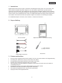
2. Scope of delivery
3.5" LCD monitor
Digital door station in weatherproof housing
Accessories
Power supply components
3. Features and functions
x
x
x
x
x
x
x
x
x
Intercom with an integrated camera and a portable 3.5" LCD color monitor thanks to its integrated battery
An existing bell - buzzer wire is easy to connect to the door station
Encrypted signal transmission between the door station and monitor
The door can be opened by pressing a button on the monitor
After pressing the door bell, images are recorded on an SD card in the monitor and can be watched
conveniently on the PC
Integrated microphone on the monitor allows speaking to the person outside
Door station for a sheltered outdoor area (protection class IP55)
Door station with batteries for use in the event of a power failure
Day/night camera with integrated IR LEDs
6
English
4. Device description
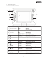
4.1 Guide to the front of the monitor
d
c
e
f
T
Q
R
U
S
Display of the current charge level:
c
Battery status display
Red:
Green:
Off:
Battery low
Charging
Battery fully charged
Device status display
d
PWR / REC
Blue:
Off:
Flashes 3x per sec.:
Flashes 1x per sec.:
Switch device on
Switch device off
Device recording
New recording in memory
e
XII
▲
Live cast:
In the menu:
Click to access event list directly
Navigate between menu items
f
◄
Live cast:
In the menu:
Reduce volume
Navigate between menu items
Q
►
Live cast:
In the menu:
Increase volume
Navigate between menu items
Standby:
Live cast:
In the menu:
Switch on monitor
Switch off monitor
Navigate between menu items
Live cast:
In the menu
Speech function
Confirm the settings and changes
Live cast:
In the menu:
Start/stop the recording
Delete the recording
Only possible with an SD card!
Live cast:
In the menu:
Door opener
Quit the sub-menu
The system will quit the menu automatically
after one minute of inactivity
R
S
T
U
Vol-
Vol+
T
OK-Taste
/ Del
/ ESC
7
English
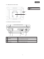
4.2
Guide to the rear of the monitor
c
Antenna
d
Stand
c
d
4.3 Guide to the connections on the monitor
c
c
d
e
f
d
Power supply
AV output
SD card slot
Power button and
menu button
e
f
5 VDC / 1 A (DC, 14.5 x 4.8 mm)
Output for displaying the screen image on a different device
using an RCA cable (not included)
Slot for using an SD card with a max. capacity of 32 GB
Switch monitor on or off
Live cast: Open / exit the menu
8
English
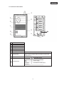
4.4 Guide to the door station
c
d
h
e
f
i
j
11
k
g
l
c
N
O
P
Q
R
S
T
Antenna
Infrared LED
Photo sensor
Loudspeaker
Microphone
Lens
Housing for attachment
Bell button
U
Pairing button
V
Reset button
11
Terminal block
When the bell button is pressed, the monitor is activated.
To connect the door station to the monitor, the pairing
button must be pressed. More information can be found
under point 5.3.
Reset button to restart the door station
{
Connection for bell
{
{
DCPower supply
{
DC+
{
Connection for door opener
UNLOCK{
UNLOCK+
9
English
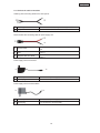
4.5 Guide to the cable connections
Cable lug with connecting cable for the door opener
c
c
d
d
Cable lug contacts
For connection to a door opener already installed
Stripped cable ends
For connection to the terminal block in the door station
Round socket with connecting cable for power supply unit
d
c
e
c
Round socket
d
Stripped cable ends
Red
e
Stripped cable end, black
Connected to the connecting cable for the power supply
unit
For connection to the terminal block in the door station
(“DC+”)
For connection to the terminal block in the door station
(“DC-”)
Power supply unit for the monitor
c
c
d
d
Wall adapter
Connection for power supply
Round plug
For connection to the monitor
Power supply unit for the door station
d
c
c
d
Wall adapter
Connection for power supply
Round plug
For connection to round sockets
10
English
5. Installation
5.1 Installation the door station
To install the door station, please proceed as described in the following:
I.
Preparation
1.
2.
3.
Please remove the rear cover of the door station and insert 6 AA batteries. Make sure the polarity is
correct.
The LEDs will then light up in green for 5 seconds.
The door station is now functional.
Important:
Weak batteries can cause the device to function incorrectly; please replace any depleted
batteries.
Important:
If you are in battery mode, please press the call button first to start operation of the door
station.
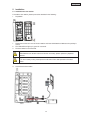
II.
Connecting the door station
11
English
1.
2.
3.
4.
5.
6.
7.
Remove the rear cover of the door station.
Attach the red cable for the round socket next to “DC+” in the terminal block.
The black connecting cable for the round socket must be attached to the terminal point “DC-”.
The two connecting cables for the cable lug must be inserted next to “UNLOCK”, with the terminals being
provided for an existing 2-cable door opener connection.
A round plug with a power supply unit can now be connected to the round socket.
Turn on the power to the power supply unit.
A door bell can be connected to the two uppermost connector points.
Important:
Please note that this contact is a potential-free relay contact, and a bell which lacks a power
supply of its own can therefore not be connected.
Important:
You also have the option of connecting your door opener directly to the door station, or to
connect an existing door opening transformer using a relay.
Important:
Please note that only DC door openers can be actuated, with AC door openers not being able
to be actuated.
More Information: www.abus.com Æ TVAC80020
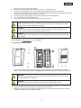
5.2 Assembling the door station
1.
Use the door bracket to help you find a suitable place for installation. Use the drill holes to mark the
surface, and drill the holes. Insert the wall plugs provided before attaching the bracket using the screws.
Important:
Before starting the installation, make sure than the wireless transmission range at the site of
the required installation is sufficient.
Important:
Before replacing the cover of the device, connect the door station to the monitor.
2.
3.
Close the housing for the door station using the four screws provided.
Place the door station into its housing and attach it using the anti-theft screws provided. The matching
screwdriver has been enclosed with the package.
12
English
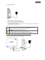
5.3 Installing the monitor
1.
2.
3.
Connect the power supply unit to the monitor.
Switch the device on. To do so, press the power button.
You can now connect the monitor to the door station.
To do so, please proceed as follows:
When the menu item “Camera set up” appears on the monitor, select the sub-item “Pairing” and press
the pairing button on the door station.
Important:
Please note that if the monitor does NOT have an external power supply, it must be
charged for at least 8 hours prior to being used for the first time.
The batteries will provide power for approx. 3.5 hours.
Important:
The integrated battery allows you to use the LCD monitor flexibly.
If the battery LED lights up in red, then the batteries must be charged. Please note that the
battery is always charged to a level which guarantees loss-free recording.
To display the monitor images on another display unit, please proceed as follows:
1. Connect the jack plug to the AV OUT connector on the monitor.
2. Then connect the RCA cable as shown in the drawing.
13
English
6. Operation
To switch the monitor ON / OFF, press and hold the power button for at least 2 seconds.
After each start, the monitor will switch to the live cast, selecting the last viewing settings.
If the
symbol is displayed, then the SD card was identified correctly by the monitor and is functioning
properly.
6.1 Live cast
Signal display
Display “Visitor is being recorded”
Battery status display for door station
Yellow: Battery charged
Red:
Battery low
Recording display: Flashes during recording
No SD card inserted
Full SD
SD card full
Err SD
SD card is not detected
SD card blocked
SD card will be overwritten when memory is full
SD card display
SD card memory capacity
NO SIGNAL
No connection between the door station and monitor
Speech function
01:12:45
Recording time
2011 05 01
14:30:11
Date / time display
14
English
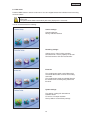
6.2 Main menu
Press the MENU button to enter the main menu. You can navigate between the individual menu items using
the arrow buttons.
Important:
Please note:
The symbols will be hidden automatically after being displayed for 10 seconds
You can choose between the following:
Camera settings:
Camera brightness
Pairing = add door stations
Recording settings:
Visiting record = visitor is being recorded
SD Card format = memory capacity on SD card
SD Card overwrite = SD card circular buffer
Event list:
The recordings are saved to sub-folders which
are named with the date on which the recording
was made.
The recordings are saved as individual files with
the duration of the recording being used as the
file name.
System settings:
Time setting = settings for date and time
Software version
TV format = TV output resolution
Factory default = restore factory settings
15
English
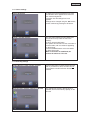
6.3 Camera settings
Camera brightness
To change the camera brightness level, press
the OK button which appears under the menu
item “Camera brightness”.
A selection bar with settings from 0 to 9
appears.
Settings can be changed using the ◄► buttons,
and be confirmed by pressing the OK button.
Pairing = add door stations
The connection between the door station and
the monitor is set up under the menu item
“Pairing”.
To do so, press the OK button.
The system will now search for the connection to
the door station, with a round arrow appearing
for 60 seconds.
Press the PAIRING button on the door station
for these 60 seconds.
When a connection is established, the
monitor will switch to a live cast.
6.4 Recording settings
Visiting Record = visitor is being recorded
Press the OK button to switch between ON and
OFF. If you switch it to OFF, the visitor will not
be recorded on the SD card when the bell is
pressed.
SD Card Format = memory capacity on SD card
This indicates the memory capacity which is
available, and the free memory capacity, on the
SD card.
16
English
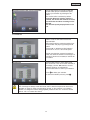
SD Card Overwrite = SD card circular buffer
Use the ◄► buttons to activate the SD card
circular buffer (ON) or to deactivate it (OFF).
Confirm your selection by pressing the OK
button.
The circular buffer is activated by default.
Important: When the memory capacity is
reached, the monitor will continue to record,
and will delete the oldest recordings on the
SD card.
The SD card capacity display flashes 0.0 in
red.
6.5 Event list
Event List
Use the arrow buttons to navigate between
folders. Press the OK button to select the
required folder.
Select the file with the required recording from
the sub-folder and play it by pressing the OK
button.
Press the ▲ or ▼ buttons to fast forward or
reverse at 2x / 4x / 8x / 16x normal speed.
Please note that when a manual recording is
made, the maximum duration of recording is 10
minutes. If this time is exceeded, a new file will
be created.
Deleting files
Press the DEL button to enter delete mode.
The current file or the current folder will flash on
the display. Use the ◄► buttons to choose
between all files or an individual file.
Press the OK button to confirm your selection.
to delete your selection.
Press
To cancel the deletion process, press
.
Important:
Your recordings are always made with sound, and it is therefore important to observe the
stipulation on page 2 in order to avoid putting yourself, or other persons, in an unlawful
situation. To change the volume during playback, please use the “Vol-” to turn the volume
down or “Vol+” to increase the volume.
17
English
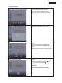
6.6 System settings
Time setting = settings for date and time
Press the ► button to toggle between
year/month/day/hour/minute.
Use the ▲▼ buttons to adjust the values.
Confirm your input by pressing the OK button.
Software version
This indicates the version of the software being
used by the door station and the monitor.
TV-format = TV output resolution
Use the ◄► buttons to select the preferred TV
format.
You can choose between NTSC and PAL.
Confirm your selection by pressing the OK
button.
Please note that the format selected can affect
the resolution.
Set to factory default =
Restore default parameters
Press the OK button to launch the factory
settings.
Confirm your selection by pressing
, and
cancel the process by pressing
.
Important:
Please note that this procedure does not
change the formatting of the SD card.
18
English
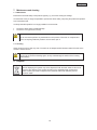
7. Maintenance and cleaning
7.1 Maintenance
Examine the technical safety of the product regularly, e.g. check the housing for damage.
If it seems that it may no longer be possible to operate the device safety, stop using the product and protect it
from unintentional use.
It is likely that safe operation is no longer possible in the event that:
x
x
The device shows signs of visible damage.
The device no longer works correctly
Please note:
You do not need to perform any maintenance on this product. There are no components to
service or anything inside the product to check. Never open it.
7.2 Cleaning
Clean the device with a clean, dry cloth. The cloth can be dampened with lukewarm water if the dirt on the
monitor is hard to remove.
Do not allow any liquids to enter the device.
Do not use any chemical cleaning agent, as they could damage the surface of the housing
(discoloration).
8. Disposal
Devices displaying this symbol may not be disposed of with domestic waste. At the end of
its service life, dispose of the product according to the applicable legal requirements.
Please contact your dealer or dispose of the products at the local collection point for
electronic waste.
19
English
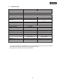
9. Technical data
Model number
Frequency
Modulation
Transmission power
Sensitivity
Wireless range
DC voltage supply
Power consumption
Battery type
Transmission channels
Viewing angle
Lens
Resolution
Number of IR LEDs
Image sensor
Range of night vision function
Video signal
Audio signal
Outputs
Storage medium
IP protection class
Rechargeable battery running
time
Dimensions
Net weight
Max. operating temperature
Door station
3.5" LCD monitor
2.4 GHz
GFSK
13dBm
-75dBm
150 m*
15V DC / 1.5 A
Max. 180mA
6 x AA 1.5 V lithium batteries
5V DC / 1 A
Max. 650mA
Li-Ion polymer battery, 3.7 V /
1,800 mA
1
--
1
85° (H) / 65° (V)
1.8 mm
640 x 480 pixels (VGA)
9 x IR LED
-1/4" CMOS
-0.8 m
--1.0 V p-p, 75 Ohm
-1.0 V p-p, 600 Ohm
Door opener: 12 V
3.5 mm jack (video)
-SD card, max. 32 GB
IP 55
-Max. 6 hours
Max. 4 hours
(WxHxD): 85 x 169 x 36 mm
0.205 kg
-10 °C - 40 °C
(WxHxD): 133 x 87 x 27 mm
0.2 kg
-10 °C - 40 °C
* The wireless transmission range depends on the environmental factors (e.g. mobile communication
masts, high-tension pylons, electrical wires, ceilings and walls, etc.).
If conditions are not favorable, the range will be limited.
20