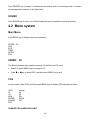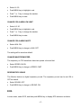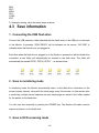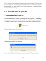
1
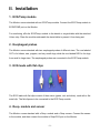
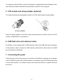
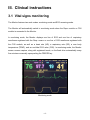
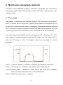
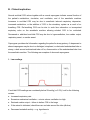
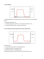
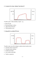
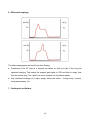
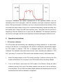
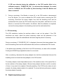
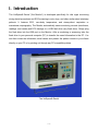
I. Introduction The VetSpecs® Dental (“the Monitor”) is developed specifically for vital signs monitoring during dental procedures and ECG screening in cats, dogs, and other similar sized veterinary patients. It features ECG, core-body temperature, and airway-direct respiration or mainstream capnography. The Monitor automatically saves monitoring records (waveforms, readings, and trends) and ECG tracings on a USB flash drive (any flash drive). Simply plug the flash drive into the USB port on the Monitor. After a monitoring or screening, take the flash drive to your personal computer (PC) to transfer the saved information to the PC. You can then review the information, email cases, and present the patient records to your clients directly on your PC or by printing out through any PC-compatible printers. The VetSpecs® Dental -1- II. Installation 1. ECG/Temp module The Monitor comes standard with an ECG/Temp module. Connect the ECG/Temp module to ECG&TEMP port on the Monitor. For monitoring, affix the ECG/Temp module to the dental or surgical table with the attached Velcro strip. Place the module underneath the dental table to prevent it from being wet. 2. Esophageal probes The Monitor comes standard with two esophageal probes of different sizes. The one labeled CAT is for kittens, cats, puppies, and very small dogs, while the one labeled DOG is for dogs from small to large sizes. The esophageal probes are connected to the ECG/Temp module. 3. ECG leads with flat clips The ECG leads with flat clips consist of three wires (green, red, and white), each with a flat metal clip. The flat clips are to be connected to the ECG/Temp module. 4. Resp. module and sensor The Monitor comes standard with a Resp. module and a Resp. sensor. Connect the sensor to the module, and then connect the module to Resp/CO2 port on the Monitor. -2- For monitoring, affix the Resp. module to the dental or surgical table with the attached Velcro strip. Place the module underneath the dental table to prevent it from being wet. 5. CO2 module and airway adapter (optional) The optional mainstream capnography consists of a CO2 module and an airway adapter. Attach the airway adapter to the CO2 module (as shown above), and then connect the CO2 module to Resp/CO2 port on the Monitor. 6. USB flash drive and extension cable The Monitor comes standard with a USB extension cable and a USB flash drive (connected to the extension cable). Connect the USB extension cable (with the flash drive) to the USB port on the back of the Monitor. 7. Connecting the power Plug the power cord into the power port on the back of the Monitor, and then into a standard 3-line 110V/60Hz power outlet in North America, or a standard 3-line 220V/50Hz power outlet in most other countries. For maximum safety, only connect the Monitor to a power outlet with three lines. -3- III. Clinical instructions 3.1 Vital signs monitoring The Monitor features two work modes: monitoring mode and ECG screening mode. The Monitor will automatically switch to monitoring mode when the Reps. module or CO2 module is connected to the Monitor. In monitoring mode, the Monitor displays one line of ECG and one line of respiratory waveforms registered with the Resp. sensor or one line of CO2 waveforms registered with the CO2 module, as well as a heart rate (HR), a respiratory rate (RR), a core body temperature (TEMP), and an end-tidal CO2 value (CO2). In monitoring mode, the Monitor saves a screen capture, along with registered trends, on the flash drive automatically every five minutes or manually upon pushing the FREEZE key. Monitoring mode -4- 1. ECG and temperature monitoring The esophageal probe labeled CAT is intended for kittens, cats, puppies, and very small dogs, while the esophageal probe labeled DOG is suitable for dogs from small to large sizes. In order for the probe to register high-quality ECG, all three metal rings must establish good contacts with the esophagus. If the probe is too small for the patient, it will not be able to establish good contacts with the esophagus. Applying the CAT probe in dogs may produce erratic ECG. Connect the esophageal probe to the ECG/Temp module. After the patient has been anesthetized and intubated, estimate how deep to insert by laying the probe onto the patient. The distal ring and middle ring should be positioned across the heart after inserted. Insert the probe into the esophagus to the depth as estimated above, and then watch the screen. If registered ECG is erratic, i.e. ECG baseline is unstable, adjust the position (depth) of the probe until stable ECG is registered. Motions induced to the patient and/or probe during the procedure may produce motion artifacts on the ECG. Tie the esophageal probe to the endotracheal probe to minimize motions if necessary. Never insert a probe into a patient not anesthetized and intubated. Do not use a probe which is defective or damaged externally. When using the esophageal probes in electrosurgery, the patient must be properly grounded as instructed in the User’s Manual for the electrosurgical unit being used. 2. Respiration monitoring The Monitor incorporates VetSpecs® proprietary airway-direct respiration monitoring technology, which provides real-time respiratory waveforms and RR. This technology is suitable for cats and dogs of all sizes, and effective and reliable even when motions are induced to the patient. To monitor respiration during dental or surgical procedures, simply insert the Resp. sensor between the breathing circuit and the endotracheal tube. -5- 3. Mainstream capnography (optional) The Monitor offers VetSpecs® proprietary mainstream capnography. This state-of-the-art technology provides real-time CO2 waveforms, end-tidal CO2 values, respiratory rates, and a respiratory sound. A. The concept Capnography is measurement and waveform display of CO2 concentration at the patient’s airway. It monitors various components of patient and anesthesia circuit/equipment as well as the critical connection between the two. A capnogram is the graphical waveform depicting CO2 concentration throughout respiration. End-tidal CO2, which can be expressed as mmHg or percentage, refers to the measurement of CO2 concentration at the end of exhalation. The normal range of end-tidal CO2 value for most mammals is 30 – 45 mmHg or 4.0 – 5.5%. It is considered to be abnormal when the end-tidal CO2 is higher than 50 mmHg (or 6.5%) or lower than 20 mmHg (or 2.5%). The diagram below shows the shape of a normal capnogram. Phase I: A near zero baseline — Exhalation of CO2-free gas contained in dead space. Phase II: Rapid, sharp rise — Exhalation of mixed dead space and alveolar gas. Phase III: Alveolar plateau — Exhalation of mostly alveolar gas. At the end of exhalation, CO2 concentration reaches the peak - end-tidal CO2 value. Phase 0: Rapid, sharp down-stroke — Inhalation. -6- B. Clinical implication Normal end-tidal CO2 values together with a normal capnogram indicate normal function of the patient’s metabolism, circulation, and ventilation, and of the anesthetic machine. Increases in end-tidal CO2 may be due to anesthetic induced respiratory depression, increased metabolism, or the addition of CO2 to the circulatory system as a result of rebreathing CO2. Re-breathing CO2 can be due to soda lime exhaustion or incompetent expiratory valve on the anesthetic machine allowing exhaled CO2 to be re-inhaled. Decreased or abolished end-tidal CO2 may be due to hyperventilation, low cardiac output, respiratory arrest, or cardiac arrest. Capnogram provides vital information regarding the patient's airway potency. A depressed or absent capnogram may be due to a dislodged, misplaced, or obstructed endotracheal tube or airway, a leak around endotracheal tube cuff or, disconnection of the endotracheal tube from the anesthetic machine. The following are examples of abnormal capnograms. 1. Low readings If end-tidal CO2 readings are consistently below 20 mmHg (or 2.5%), look for the following causes: ● Increased respiratory rate ● Excessive mechanical ventilation – minute volume ventilation too high ● Reduced cardiac output – failure to deliver CO2 to the lungs ● If the animal is intubated, check there are no leaks around the tube (dilution) ● Decreased metabolic activity – e.g. hypothermia -7- 2. High readings If end-tidal readings are consistently above 50 mmHg (or 6.5%), look for the following causes: ● Decreased respiratory rate ● Insufficient mechanical ventilation – minute volume ventilation too low ● Increased metabolic activity – shivering, hyperthermia 3. Rise in base-line caused by increased levels of inspired CO2 Possible causes: ● Insufficient fresh gas flow in non-rebreathing circuit ● Excessive dead space in anesthetic circuit ● Exhausted soda-lime in rebreathing circuit Note that at the same time the end-tidal CO2 value will also start to rise. -8- 4. Increase in the slope of phase II and phase III Possible causes: Reduced ability to expire – e.g. ● Block ET tube ● Bronchial disease / asthma ● Upper airway obstruction ● Faulty expiratory valve 5. Abrupt fall in end-tidal CO2 level Possible causes: any effect leading to sudden reduced cardiac output ● Pulmonary artery compression ● Pulmonary artery embolism ● Sudden hemorrhage ● Acute cardiac tamponade ● Cardiac compression -9- 6. Differential emptying The above capnograms can result from the following: ● Positioning of the ET tube at or beyond the carina, so that one side of the lung has impaired emptying. This makes the retained gas higher in CO2 and later to empty than from the normal lung. The “spike” can occur anywhere in the plateau phase. ● Any functional blockage of a major airway, below the carina – foreign body, mucous, compressed airway, etc. 7. Cardiogenic oscillations - 10 - Cardiogenic oscillations are ripples superimposed on the expiratory plateau and the descending limb of the capnogram, which are caused by small gas movements inside the airway. Although cardiogenic oscillations can occur in any animal where the pulsations of the aorta and heart cause areas of lungs to be compressed and thereby emptied and filled, they are typically seen in large dogs with slow respiratory rates. The guide to the fact that this is happening is that the oscillations are in synch with the heartbeats. The displayed respiratory rate can be much higher than the actual respiratory rate when cardiogenic oscillations occur. C. Operation instructions 1. CO2 module calibration The CO2 module will automatically start calibrating upon being powered on. In other words, turning on the Monitor, or connecting the CO2 module to the Monitor, automatically triggers the CO2 module to calibrate. “CO2 CAL” is displayed when the CO2 module is being calibrated. The calibration takes about three minutes. Upon completing the calibration, “CO2 CAL” goes away. To ensure the CO2 module to be calibrated correctly, follow these steps: 1. Attach the airway adapter on the CO2 module (see page 3) before connecting the CO2 module to the Monitor. Do not power on the CO2 module without the airway adapter. 2. Turn on the Monitor, and connect the CO2 module to the Monitor. During the entire calibration process, both ends of the airway adapter must be open in the air and away from the patient. Do not insert the airway adapter between the breathing circuit and the endotracheal tube until the calibration is completed. - 11 - If CO2 was detected during the calibration, or the CO2 module failed to be calibrated properly, “PLEASE RE_CAL” (in red) would be displayed. You would need to re-calibrate the CO2 module by disconnecting it from the Monitor and then re-connect it. 3. During a monitoring, if the Monitor is turned off, or the CO2 module is disconnected from the Monitor, you must re-calibrate the CO2 module before continuing the CO2 monitoring. Disconnect the airway adapter from both the breathing circuit and the endotracheal tube, place the CO2 module away from the patient, and then turn on the Monitor or reconnect the CO2 module to the Monitor. After the calibration is completed, re-insert the airway adapter to the breathing circuit and the endotracheal tube. 2. CO2 monitoring The CO2 waveforms indicate the real-time airflow in and out the patient. If the CO2 waveforms are erratic, check the patient respiratory status and the placement of the endotracheal tube. Adjust the endotracheal tube and/or bag the patient if necessary. During a monitoring, if “PLEASE RE_CAL” is displayed, disconnect the airway adapter from both the breathing circuit and the endotracheal tube, and then re-calibrate the CO2 module. If the patient stops breathing (a flat line for the CO2 waveforms), an alarm will be sounded. Pushing the SOUND key suspends the alarm for one minute. After a monitoring, disconnect the airway adapter from both the endotracheal tube and the breathing circuit, but leave the airway adapter on the CO2 module. The airway adapter is semi-disposable because of the sensitive nature of the optical film on the two windows of the airway adapter. After an airway adapter has been used for a number of times, it may need to be replaced. Generally speaking, if the CO2 function does not work properly, the airway adapter needs to be replaced. To ensure the best performance, replace the airway adapter frequently. D. Digital respiratory sound - 12 - The CO2 module offers a digital respiratory sound originated from real-time CO2 measurements. The rhythm of the sound reflects the respiratory rate. The respiratory sound allows continuously assessing the patient’s respiratory status without constantly watching the screen. The respiratory sound can be set ON or OFF in the menus, and the setting will be saved as default. The volume of the sound can be adjusted. 3.2 ECG Screening The Monitor features ECG leads with flat clips, designed specifically for ECG screening in cats, dogs, and other similar-sized animals. For ECG screening, apply the flat clips to the patient, and disconnect both the Resp. module and the CO2 module from the Monitor. The Monitor will automatically enter into ECG screening mode, displaying cascaded two lines of ECG. ECG screening mode 1. Applying the flat clips Attach the foreleg lead(s) to the appropriate foreleg just above the elbow and the rear leg - 13 - lead(s) to the appropriate rear leg immediately proximal to the stifle. It is not necessary to clip hair. Wet all three contact sites thoroughly with saline. In order to register interferencefree ECG, adequate amount of saline must be applied to all three contact sites. When using the flat clips for ECG monitoring, it is recommended to wet all three contact sites with saline and then apply ECG gel to these sites. 2. Placements of the leads With the ECG leads, the Monitor can record Lead-I, Lead-II, and Lead-III ECG, one Lead at a time. Lead-II is the Lead of choice for both monitoring and screening. Placements of leads (flat clips) to record different Leads of ECG are listed as below: LEAD-II ECG GREEN lead attaches to RIGHT REAR LEG RED lead attaches to LEFT REAR LEG WHITE lead attaches to RIGHT FORELEG LEAD-I ECG GREEN lead attaches to RIGHT REAR LEG RED lead attaches to LEFT FORELEG WHITE lead attaches to RIGHT FORELEG LEAD-III ECG GREEN lead attaches to RIGHT REAR LEG RED lead attaches to LEFT REAR LEG WHITE lead attaches to LEFT FORELEG The patient should be laid on its side, usually on a towel or rubber mat, and relaxed. Trembling and panting may produce motion artifacts on ECG. For more instructions on ECG screening, refer to pages 19 and 30 - 32. - 14 - IV. Operational instructions The POWER switch is located on the back of the Monitor. Always turn off the Monitor to refresh its internal memory after a monitoring or screening. Otherwise, the data of the previous patient will be mixed with the data of the next patient. 4.1 Control panel MENU Push MENU key to display main menu, enter submenus, or change settings in submenus. Push or key to select items, input new numbers, or change the volume of the speaker. TREND Push TREND key to display trends of HR, RR, Temp., and CO2. One hour of trends are displayed. When more than one hour of trends is recorded, push or key to change pages. FREEZE - 15 - Push FREEZE key to freeze or release the waveforms, and in monitoring mode, to make a screen capture and save it on the flash drive. SOUND Push SOUND key to turn on or off the heartbeats sound, respiratory sound, and alarm. 4.2 Menu system Main Menu Push MENU key to display main menu as below. SPEED: 50 CO2 ECG TEMP SETUP ESC SPEED: 50 The Monitor features two waveform speeds, 50 (default) and 25 mm/s. Select 50, push MENU key to change to 25, Push or key to select ESC, and then push MENU key to exit. CO2 In main menu, select CO2, and then push MENU key to display CO2 submenu as below. UNIT: HI: LO: ALM: SPEED: SOUND: ESC mmHg 50 20 ON SLOW OFF CHANGE CO2 ALARM HIGH LIMIT - 16 - Select HI: 50 Push MENU key to highlight in red. Push or key to change the number. Push MENU key to enter. CHANGE CO2 ALARM LOW LIMIT Select LO: 20 Push MENU key to highlight in red. Push or key to change the number. Push MENU key to enter. CHANGE CO2 ALARM ON/OFF Select ALM: ON Push MENU key to change to ALM: OFF The setting will be saved as default. CHANGE WAVEFORM SPEED The respiratory or CO2 waveforms have two speeds: slow and fast. Select SPEED: SLOW Push MENU key to change to SPEED: FAST RESPIRATORY SOUND The Monitor features a digital respiratory sound. The respiratory sound can be set ON or OFF as default. Select SOUND: OFF Push MENU key to change to SOUND: ON ECG In main menu, select ECG, and then push MENU key to display ECG submenu as below. - 17 - HI: LO: ALM: GAIN: SOUND: ESC 400 050 ON AUTO ON To change a setting, follow the same steps as above. CHANGE GAIN The ECG amplifier features six levels (1/2, 1, 2, 4, 8, and 16) of sensitivities (gains). The Monitor automatically adjusts the gain to display ECG in an optimal size (as large as possible without saturation). To suspend the automatic gain adjustment, change the gain setting from AUTO (default) to CAL. On CAL, the gain of the amplifier will be kept at the level 1 all the time. To change the setting, Select GAIN: AUTO Push MENU key to change to GAIN: CAL HEARTBEATS SOUND The Monitor features a heartbeats sound, which can be set ON or OFF as default. Select SOUND: ON Push MENU key to change to SOUND: OFF TEMP In main menu, select TEMP, and then push MENU key to display TEMP submenu as below: HI: LO: ALM: UNIT: ESC 105 095 OFF ºF To change a setting, follow the same steps as above. SETUP In main menu, select SETUP, and then push MENU key to display SETUP submenu. HOUR: - 18 - MIN: SEC: MON: DAY: YEAR: ESC To change a setting, follow the same steps as above 4.3 Save information 1. Connecting the USB flash drive Connect the USB extension cable (attached with the flash drive) to the USB port on the back of the Monitor. In seconds, “DISK READY” will be indicated on the screen. “NO DISK” is indicated when the flash drive is not plugged in. Each time when the flash drive is plugged in or the Monitor is powered on with the flash drive connected, a new folder will automatically be created on the flash drive. The folder will automatically be named PET01, PET02, PET03 … as shown below. 2. Save in monitoring mode In monitoring mode, the Monitor automatically saves, on the flash drive, information on the screen (screen capture), along with the trends page, every five minutes. In other words, after a monitoring, multiple screen captures and one trends page are saved in the folder created for the patient on the flash drive. You also can save manually by pushing the FREEZE key. The Monitor will make a screen capture and save it on the flash drive. 3. Save in ECG screening mode - 19 - In ECG screening mode, the Monitor automatically and continuously saves ECG on the flash drive. The Monitor will automatically start saving ECG as soon as valid ECG is registered, and automatically stop saving when ECG is no longer registered. Up to 99 screen captures can be saved for one screening. 4.4 Transfer data to your PC 1. Install the software to your PC The VetSpecs® Dental PC software is compatible with any PCs using a Windows® XP operating system. Insert the software CD into a CD drive on the PC, and then open the CD. To install the program on the PC, simply double click the file named “VetSpecs Dental.exe”. The window below pops up. Click Yes button. The window below pops up. Click OK button. An icon named “VetSpecs Dental” appears on the desktop of the PC, as shown below: - 20 - 2. Create a master folder on the hard drive It is highly recommended to create a new folder on the hard drive to be the master folder for storing all patient data recorded by the Monitor before you transfer any data to the PC. You can give any name to the master folder. For example, you can name it “My VetSpecs Data”. 3. Transfer data to the hard drive Remove the flash drive from the Monitor, and insert it to a USB port on the PC. The flash drive should be recognized by the PC automatically, and indicated as Removable Disk under My Computer. It is highly recommended that you copy all folders on the flash drive to the master folder or a folder inside the master folder on the same day they were recorded, and then delete all folders on the flash drive. Otherwise, you may get confused with the folders on the flash drive. You must rename all these folders immediately after they are copied to the hard drive, and you should rename them in a way that they can be identified easily. For example, you may rename a patient’s folder with the patient’s name, ID number, or name + ID number as below: There can be multiple folders inside a patient’s folder. For example, the data recorded in a - 21 - monitoring on July 1, 2005 are stored in the folder “M-07-01-05”, while the data recorded in an ECG screening on July 1, 2005 are stored in the folder “ECG-07-01-05”. 4.5 Review and print 1. Open the program from the desktop Double click the icon “VetSpecs Dental” on the desktop to open the program. A window titled VetSpecs Dental pops up as shown below. - 22 - Click the Open button located at the lower right corner of the window, or click File menu and select Open, as shown below, to go to the patient’s folder. If you see the window is partially out of the screen, the screen resolution setting on the PC is too low to display the entire window. To adjust the screen resolution, go to Control Panel window and double click Display icon, as shown below. In Display Properties window, click Settings. In the window below, set Screen resolution to 1024 by 768 pixels or higher, and then click Apply button and OK button. - 23 - 2. Review and print monitoring records To review saved monitoring records, go to the patient’s folder and then open it. There may be a number of files in the folder as shown below. WAVE00.VDT, WAVE01.VDT, WAVE02.VDT, and WAVE03.VDT…are screen captures, and TREND.VDT is the trends page. You can open any of them by double clicking on the file. - 24 - Four-file display format Four screen captures are opened up in one window. To select one of the four files, place the cursor in the waveform area (see the window on the previous page), and then click the left key on the mouse. The readings displayed on the right side of the window correspond to the selected screen capture. You can delete any screen captures. To delete a screen capture, place the cursor in the waveform area, and then click the right key on the mouse. To display only one screen capture, place the cursor in the waveform area of a selected screen capture, and then double click the left key. The selected screen capture is displayed in the whole window, as shown below. To go back to the four-file display format, place the cursor in the waveform area, and then double click the left key. - 25 - Single-file display format To change pages, click PgDn or PgUp button at the lower right corner of the window. To print a screen capture, click PRINT button. The screen capture will be printed through the default printer of the PC, as shown on the next page. To view trends, in a screen capture window, click Trend button at the upper left corner of the window, as shown below. The TREND window pops up. - 26 - To print the trends page, click PRINT button. The trend page will be printed through the default printer of the PC, as shown on page 28. - 27 - - 28 - To input patient information, click PetInfo button at the upper left corner of the window. The PetInformation window pops up, as shown below. Type in patient information and/or comments, and click Save button. You can make an update in this window at any time. When printing, the patient information will be printed on the top of each printout. To print the diagnostic comments, click the PRINT button. - 29 - 3. Review and print ECG To review saved ECG, go to the patient’s folder and then open it. There may be multiple screen captures in the folder. You can open any screen capture by double clicking the file. Four screen captures are opened up in one window as shown below. - 30 - Four-file display format To display only one screen capture in the window, place the cursor in its waveform area, and then double click the left key on the mouse. - 31 - Single-file display format To view ECG screen by screen, click PgDn or PgUp button. To go back to four screen captures in one window, double click the left key on the mouse. To print a screen capture, click PRINT button. The screen capture will be printed through the default printer of the PC, as shown on the next page. - 32 - V. Troubleshooting 1. ECG/Temp Channel - 33 - Problems Possible Causes After inserting the Not all metal rings have esophageal probe, the ECG established a good contact is erratic. with the esophagus. Recommended Actions 1. Make sure an appropriate sized probe is used. 2. Adjust the position (depth) of the esophageal probe. After inserting the The esophageal probe is Adjust the position (depth) of esophageal probe, the ECG inserted too shallow or deep. the esophageal probe. After inserting the A wire inside the esophageal Use another esophageal esophageal probe, “LEAD probe was damaged. probe. After inserting the The temperature sensor Use another esophageal esophageal probe, no inside the esophageal probe probe. temperature is registered. was bad. After applying the ECG Good electrode-to-tissue Make sure all three clips are leads, the ECG is erratic or contacts are not established. applied to the patient is too small. OFF” is still displayed. having a lot of interference. properly, and soak all three contact sites with saline. “LEAD OFF” is still displayed, A lead (wire inside) was after applying all three leads damaged. Use another set of leads. on the patient. “ECG OFF” is displayed while The ECG/Temp module is The ECG/Temp module the ECG/Temp module is needs to be serviced. malfunctioning. connected to the Monitor. 2. Respiration Channel Problems Possible Causes The respiratory waveforms A wire inside the Resp. are a flat line. sensor was damaged. - 34 - Recommended Actions Use another Resp. sensor. After the Resp. module is The Resp. module is The Resp. module needs to connected, the Monitor does malfunctioning. be serviced. not switch to the monitoring mode. 3. Mainstream Capnography Problems Possible Causes Recommended Actions “PLEASE RE-CAL” (in red) is 1. CO2 was detected during Re-calibrate the CO2 module displayed. the calibration. 2. The CO2 module failed to be calibrated properly. 3. Registered CO2 value is erroneously high. as instructed on pages 11 and 12. If the CO2 module still can not be calibrated properly, try another airway adapter. CO2 waveforms stay a flat The CO2 module was Re-calibrate the CO2 module line, and both CO2 reading calibrated without the airway with the airway adapter. and RR stay 00. adapter being attached. The CO2 function seems not Bad airway adapter. working properly. Insert another airway adapter, and then re-calibrate the CO2 module. “CO2 CAL” is not displayed The CO2 module is Turn off the Monitor and then after connecting the CO2 malfunctioning. turn it back on. If still the module to the Monitor. same, the CO2 module needs to be serviced. VI. Maintenance Keep the Monitor away from heat sources, liquid, and flammable or corrosive materials. Avoid dusty, humid, or wet places. Do not block the ventilation vent. - 35 - When using the Monitor in multiple procedures in a row, make sure to turn off the Monitor after each procedure. Keeping the Monitor powered on between procedures reduces the life span of the Monitor. Clean the esophageal probes and ECG leads with a paper towel wet with alcohol after each use. Disconnect them from the ECG/Temp module before cleaning. Never wash the CO2 module or immerse it in liquid. Do not use alcohol to clean the CO2 module or the airway adapter. If necessary, wash the airway adapter with soapy water and then shake it dry. Never autoclave any accessories or modules. Never modify any accessories. Never use any VetSpecs® accessories on any other monitors not made by VetSpecs. Never use on the Monitor any cables, leads, sensors, or probes which were not provided by VetSpecs. Never have the Monitor or its modules or accessories serviced by any unauthorized person. Warranty for the Monitor would automatically be voided if any of the above occurred. VII. Specifications Screen: Dimensions: Weight: Power Requirements: ECG Leads: ECG Sensitivities: Waveform Speeds: HR Range: 5.5” color TFT LCD 7.5” X 11” X 6.5” (D/W/H) 6 lbs 110V/60Hz or 220V/50Hz Lead-I, Lead-II, or Lead-III Automatically adjusted (X1/2, 1, 2, 4, 8, and 16) 25 mm/s and 50 mm/s (default) 0 - 400 bpm Temp. Range: RR Range: CO2 Range: 85 F - 113 F 0 - 150 brpm 0 - 100 mmHg or 0 - 10% VIII. Modules and accessories Dental-A Standard: One ECG/Temp module, one CAT esophageal probe, one DOG esophageal probe, one set of ECG leads with flat clips, one Resp. module, one Resp. sensor, one USB flash drive, one - 36 - USB extension cable, one power cord, one VetSpecs® Dental PC software CD, and one VetSpecs® Dental User’s Manual. Dental-B Standard: One ECG/Temp module, one CAT esophageal probe, one DOG esophageal probe, one set of ECG leads with flat clips, one CO2 module, one airway adapter, one USB flash drive, one USB extension cable, one power cord, one VetSpecs® Dental PC software CD, and one VetSpecs® Dental User’s Manual. Optional: ECG leads with limb plates, esophageal probe for exotics. IX. Customer services For technical support or ordering accessories, please call (770) 409-9291 LIMITED WARRANTY VetSpecs, Inc. (“VetSpecs”) warrants the VetSpecs® Dental main unit (hereinafter “the Monitor”) to be free from defects in materials and workmanship, when stored under appropriate conditions and given normal, proper and intended usage, for TWO (2) years from the date of delivery of the Monitor to the original end user purchaser (“Buyer”). VetSpecs agrees during the applicable warranty period - 37 - to repair or replace defective monitor without cost to Buyer. VetSpecs shall not have any obligation under this Limited Warranty to make replacements which result, in whole or in part, from catastrophe, fault or negligence of Buyer, or anyone claiming through or on behalf of Buyer, or from improper use of the Monitor, or use of the Monitor in a manner for which it was not designed, or by cause external to the Monitor. The ECG/Temp module, Resp. module, CO2 module, flash drive, and USB extension cable are covered by a six-month limited warranty. The esophageal probes, ECG leads with flat clips, ECG leads with limb plates, Resp. sensor, and airway adapter are covered by a one-month limited warranty. The Monitor PC software is covered by a life-time replacement warranty. Buyer shall notify VetSpecs of any product which it believes to be defective during the warranty period. Such product shall be returned by Buyer, transportation and insurance prepaid, to VetSpecs for examination and testing. VetSpecs shall repair or replace any such product found to be so defective and return such product to Buyer, transportation and insurance prepaid. The provisions of the foregoing Limited Warranty are exclusive and are expressly in lieu of any other warranty, whether express or implied, written or oral. VetSpecs neither assumes nor authorizes any employee, agent, distributor or other person or entity to assume for it any other liability in connection with the manufacture, sale, supplying or use of the Monitor. VetSpecs’ liability arising out of the manufacture, sale or supplying of the Monitor or its use or disposition, whether based upon warranty, contract, tort or otherwise, shall not exceed the actual purchase price paid by Buyer for the Monitor. In no event shall VetSpecs be liable to Buyer or any other person or entity for special, incidental or consequential damages (including, but not limited to, loss of profits, damages to properties, and injuries to the patient and/or the user) arising out of the manufacture, sale, supplying or use of the Monitor. The foregoing Limited Warranty extends to Buyer only and shall not be applicable to any other person or entity including, without limitation, customers of Buyer. - 38 -