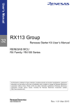
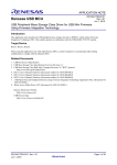
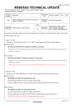
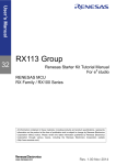
1
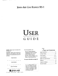
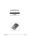
Application note RX113 Group CTSU Basis of Cap touch detection R30AN0218EJ0100 Rev 1.00 25th Dec 2014 Summary RX113 group is incorporated a hardware (Capacitive Touch Sensor Unit; CTSU) that detects human body contact by measuring capacitance existed between touch electrode and human body. This application note introduces the principle of capacitive touch detection as well as explains the detail of current-frequency conversion system that is used in RX113. The Target Device RX113 Group Contents Introduction ........................................................................................................................................ 2 The Basic of Capacitive Touch Switch .............................................................................................. 2 The Capacitive Touch Detection System of Renesas ....................................................................... 8 The method of Capacitive touch key constructing by CTSU .......................................................... 15 Noise Immunity................................................................................................................................ 30 Appendix ......................................................................................................................................... 35 R30AN0218EJ0100 25th Dec 2014 Rev 1.00 Page 1 of 37 RX113 Group CTSU Basis of Cap touch detection Introduction Touch switch using the capacitance generated between human body and touch electrode is widely used for home appliances, AV equipment, automotive, and industrial equipment including smart phones. Cap touch switch is robust as there is no mechanical parts and superior in design to the placement of the switch to the curved surfaces. Also it is possible to detect the movement of the finger to one or two dimensional direction which was difficult to achieve by the conventional switch. This application note introduces the basis of capacitive touch, the detail of capacitive touch switch detection of Renesas’ original system, and examples of capacitive touch switch with our system. The Basic of Capacitive Touch Switch The capacitive touch switch is different from the popular switch that has the electrical contact, and it detects the status of the switch (ON or OFF) by measuring a small capacitive (1pF or less) change which exists between the electrodes and the human body. There are several ways to measure the capacitance and convert it to the status of switch. The easiest way is called a relaxation oscillation method which forms a low-pass filter (LPF) by capacitance and resistance, and measures as changes in capacitance=changes in time constant of LPF. This method is widely used because the circuit is simple and the special capacitance measurement circuit is not necessary. However, it is vulnerable to noise in general and it may misjudge the status of switch by the effect of invertor noise generated from appliances and lighting equipment. For the capacitive touch detection method which Renesas has developed, it adopts the switchedcapacitor filter in order to achieve both high sensitivity and noise immunity, and judges the status of switch by converting the capacitance to current, amplifying and digitizing. (Figure 2-1) 2-2 Capacitance current conversion 2-3 Digitalization of current 2-4 Judge the status of switch Notify the status of switch 2-1 Generation of Capacitance Figure 2-1 Flow of capacitance touch switch detection (number-number is the chapter number) The basic of capacitance touch switch detection is described in this chapter in accordance with the flow of Figure 2-1. R30AN0218EJ0100 25th Dec 2014 Rev 1.00 Page 2 of 37 RX113 Group CTSU Basis of Cap touch detection Generation of Electrostatic Capacity The mechanism of existing electrostatic capacity is shown in Figure 2-2. Parasitic capacity (Cp) is existed between an electrode in the space and the conductive materials (ground pattern or metal frame etc.) of its surroundings. At this time, finger capacity (Cf) is newly generated between the human body and electrode if the human body approaches, and it is grounded to the ground through the sole capacity (Cs) which is generated between the sole of feet and the ground through human body as a conductor. (The red line in the figure) Figure 2-2 Generation of electrostatic capacity (self-capacitance method) Total capacity that is occurring on the electrode is shown the following equation. Total Capacity = Cp + Cf The capacitive touch switch judges the status of switch by detecting the increase Cf of capacitance by human body and measures the capacitance on electrode by cyclic measurement. Furthermore, this is a general self-capacitance method as a capacitive touch switch. It is configured by a single electrode. The shape of electrode is also simple and circuit configuration can be implemented relatively easily. However, it is necessary to consider the structure to reduce Parasitic Capacity as much as possible because the smaller Cf against Cp, the more difficult to configure as ensuring the dynamic range of capacity detection circuit is necessary. There is a mutual capacity method with pair of electrode in contrast with the self-capacity method with a single electrode. The example of mutual capacity method is shown in Figure 2-3. The mutual capacity method is configured by receiving electrode, transmitting electrode, and pulse generators. When AC pulse is inputted to the transmitting electrode, Field Coupling is generated between the receiving electrodes. If a human body approaches in this state, the part of the electric field moves to the human body and the electric field between electrodes decrease. It is possible to detect the approach of a human body if the decrease of electric field is measured by receiving electrode. The circuit of the mutual capacity method is more complicated than self-capacity method. However, it is possible to decrease the influence of parasitic capacity, which is a problem in a self-capacity method, and also possible to increase the strength of electric filed to be generated and make the detection to high sensitive. It is mainly used for a touch screen and a proximity sensor. R30AN0218EJ0100 25th Dec 2014 Rev 1.00 Page 3 of 37 RX113 Group CTSU Basis of Cap touch detection Figure 2-3 Mutual capacity method Capacitance-Current Conversion Switched capacitor filter (SCF) is used as the way of converting the amperage described in the chapter 2.1 from the capacitance that generates between human body and electrode. SCF is structured by capacitor, power, two switches and the control signal to toggle two switches ON/OFF alternatively. Figure 2-4 SCF configuration and Charge and discharge operation of capacitor SW1 and SW2 are controlled by the pulse as exclusive control when one turns ON and the other turns OFF. When SW1 turns ON and SW2 turns OFF, the capacitor is charged as described in Figure 2-4 (the left). After switching SW1 to OFF, SW2 to ON, the capacitor is discharged as describe in Figure 2-4(the right). R30AN0218EJ0100 25th Dec 2014 Rev 1.00 Page 4 of 37 RX113 Group CTSU Basis of Cap touch detection i t 0 SW1 ON OFF ON OFF OFF SW2 OFF ON OFF ON ON Figure 2-5 the status of SW1 and SW2 and the relationship of electric current i The status of SW when they cyclically repeat turning ON and OFF and the relationship of current i on the circuit are shown in Figure 2-5. The electric charge of the capacitor is 0 at the moment SW1 turns ON and the current flows into capacitor rapidly. As the charge of the capacitor progresses, the amperage decreases, and the current stops at full of charge. After that, the electric charge of capacitor flows into the ground when SW2 turns ON. This current (Figure 2-5 dashed line) does not appear on the power supply side because SW1 turns OFF. When cyclically repeats this operation, a certain amount of current flows intermittently synchronized with turning ON and OFF. When doubling the capacity of the capacitor while maintaining the ON/OFF cycle of SW, the amperage also be doubled. (Figure 2-6) Also as set the capacity of capacitor the same amount, doubling the ON/OFF cycle of SW makes the amperage double. (Figure 2-7) i t 0 Figure 2-6 double external capacitor capacity i t 0 Figure 2-7 double SW switching frequency From these relationships, the following equation holds by written the circuit current as i, the switch frequency as f, capacitor capacity as c, and circuit voltage as v. i = fcv In this case, if f and v are constant, i is proportional to c. In this way, the mechanism of converting the changes of capacitance by human approach to changes of current is feasible by SCF. Conversion ratio of capacitance and amperage can be changed by adjusting f and v. R30AN0218EJ0100 25th Dec 2014 Rev 1.00 Page 5 of 37 RX113 Group CTSU Basis of Cap touch detection Digitalizing of Current The capacity of the capacitor which is converted to amperage is digitalized by means of the circuit that changes oscillating frequency in accordance with amperage and the counter that counts pulse outputting from the circuit. The flow of digitalizing is shown in Figure 2-8. The electric current from SCF flows alternatively because the capacitor with SCF charges and discharges continually. This alternative current is smoothed by the power supply circuit connected SCF. The current is sent to the current oscillator that varies oscillation frequency in proportion to amperage, and converted to oscillation frequency. This pulse is sent to the counter, and the counter holds it by measuring the number of pulses for a certain time. The graph in the figure shows the example when the frequency of SCF is fixed and the capacitor capacity is doubled, then the amperage and the frequency of current oscillator become double. Eventually, the count value (6→12) measured by counter also becomes double. Figure 2-8 Flow of current digitalization ON/OFF switch judgment As explained in chapter 2.1, for self-capacitance method, it is possible to judge by the increase of capacitance whether or not the human body is touched to the electrode. It is possible to detect the contact of human body by regularly performing the capacitance measurement process of above chapter 2.1~2.3 and measuring the changes of the measurement value. The flow of ON/OFF switch judgment when finger approaches the electrode and away again is shown in Figure 2-9. Measurement of the capacitance is carried out at a regular interval as the measured timing shown in the figure. Count value obtained by measurement holds the certain count value when finger is away from electrode as the blue line on the graph. It increases with the increase of capacitance when finger is approached, and decreases and becomes to a certain value when the finger is away again. At this time, set the count value when finger is away as a standard value (green dashed line) and the value that added a certain value from the standard value as threshold value. Then, it will be possible to switch ON/OFF as capacitive touch switch by switching ON when measured count value exceeds the threshold value and switching OFF when the value is under the threshold value. In addition, sensitivity adjustment of capacitive touch switch can be done by changing the threshold value. Also, chattering suppression of the switch and the reaction rate can be adjusted by changing the cycle of measurement timing R30AN0218EJ0100 25th Dec 2014 Rev 1.00 Page 6 of 37 RX113 Group CTSU Basis of Cap touch detection and averaging the multiple times of count value. The detail is described later. Figure 2-9 ON/OFF switch judgment R30AN0218EJ0100 25th Dec 2014 Rev 1.00 Page 7 of 37 RX113 Group CTSU Basis of Cap touch detection The Capacitive Touch Detection System of Renesas Renesas’s original capacitive touch detection system has both high sensitivity and high noise immunity by CTSU (Capacitive Touch Sensing Unit). It has the analog circuit for capacity detection that is low impedance and high sensitivity, and the analog-digital conversion circuit that achieves excellent temperature characteristic and linearity. Also, Capacitive touch API (Application Program Interface) utilizing 32bitCPU of high speed/high efficiency facilitates the development of capacitive touch system without being aware of the hardware. These hardware and software are explained in this chapter. Overview Overview of Renesas’s capacitive touch detection system is shown in figure 3-1. The system is divided into a hardware part and a software part. The Hardware part includes I/O Driver part that connects directly to touch electrode and convert the capacity to electric current in pulse drive, Analog Front End part that converts the electric current to frequency, and Digital Control part that passes capacity measurement value to software by controlling these blocks. The Software part includes Device Driver that controls hardware, Middleware API that performs position determination of finger by slider, wheel, and matrix electrode, and Middleware API and user application that performs I/F with upper application. Software Layer User Application API Middleware Physical Driver Layer Hardware Digital Control Analog Front End I/O Driver Figure 3-1 Renesas’s capacitive touch system R30AN0218EJ0100 25th Dec 2014 Rev 1.00 Page 8 of 37 RX113 Group CTSU Basis of Cap touch detection Hardware Overview Overall view of hardware is shown in figure 3-2. Hardware is divided into I/O Driver part, Analog Front End part, Digital Control part, and CPU part. Operation overview is as follows. 1) Amperage outputting from I/O Driver changes when finger approaches to electrode which is connected to I/O Driver. Each I/O Driver is switched in switch matrix and sequentially performed the measurement in order to measure multiple electrodes. 2) I/O Driver is smoothed by an external LPF, sent to current oscillation circuit (ICO), and performed the electric current-frequency conversion. 3) Digital Control part counts frequency of certain period of time outputting from ICO. Capacitance generated in electrode part is converted to count value in the end and saved to the register. 4) Count value is automatically transferred to RAM through data transfer circuit. Finger approach is detected by the interruption of measurement completion to CPU at the same time as the data transfer, and then software refers to the value and monitors the changes of count value. Figure 3-2 overall view of hardware R30AN0218EJ0100 25th Dec 2014 Rev 1.00 Page 9 of 37 RX113 Group CTSU Basis of Cap touch detection I/O Driver & Drive pulse generator The structure of I/O Driver is shown in figure 3-3. I/O Driver is structured by switched capacitor filter. For I/O Driver, two pair of switch is reversely controlled by drive pulse supplied from the Digital part. In accordance with the above equation (i=FCV), amperage i changes depending on constant voltage v that is supplied from Touch VDD regulator, capacitance c that is generating to electrode, and frequency f of drive pulse. This electric current is smoothed through LPF and sent to ICO in the Analog Front End part. Figure 3-3 diagram of I/O Driver Analog Front End The structure of AFE is shown in figure 3-4. AFE part is mainly structured by power generation part and ICO part. The capacitance converted to electric current in I/O Driver part is converted to frequency in AFE part, and sent to Digital control part. Figure3-4 R30AN0218EJ0100 25th Dec 2014 Rev 1.00 Analog Front End Page 10 of 37 RX113 Group (a) CTSU Basis of Cap touch detection Touch VDD regulator & Sensor ICO The structure of Touch VDD Regulator is shown in figure 3-5. Touch VDD Regulator is structured by Voltage Regulator that supplies voltage to I/O Driver, Current offset to offset the detected electric current, and current mirror that passes electric current to ICO part. ICO is an oscillator that changes oscillating frequency depending on the input electric current, and increases the number of frequency in proportion to the increase of the current. Current offset is a mechanism to offset the amount of electric current in order to reduce the influence of the parasitic capacitance included in the current that is measured as an electrostatic capacitance. Detail is described later. Figure3-5 Touch VDD Regulator & Sensor ICO (b) Basic current generator, Reference ICO & ICO for spread spectrum The structure of Basic current generator, Reference ICO, and Spread spectrum ICO is shown in figure 3-6. These two ICO differ in a role. The pulse generated in Spread spectrum ICO is eventually sent to I/O Driver and used for frequency diffusion of drive pulse of SCF. The other Reference ICO is used for comparison of Sensor ICO which is mentioned above. Detail of how to use is described later respectively. Figure3-6 Basic current generator, Reference ICO & for spread spectrum Basic current generator is structured by Voltage Regulator to supply electric current with a constant voltage, and Current Modulator and Current Offset that supply controlled electric current to ICO through Current mirror. Voltage Regulator is the same as the structure of Voltage Regulator in Touch VDD Regulator above, and supplies a constant voltage to subsequent current through Current mirror. Current modulator modulates electric current outputting from R30AN0218EJ0100 25th Dec 2014 Rev 1.00 Page 11 of 37 RX113 Group CTSU Basis of Cap touch detection Voltage Regulator in order to diffuse frequency of subsequent ICO for spread spectrum. As shown in the graph of figure 3-6, as a result, waveform that ICO for spread spectrum output is modulated to FM and sent to Drive pulse generator of Digital control part. Current Offset controls the output frequency of subsequent Reference ICO by restricting the current output from Voltage Regulator. 3.2.4 Digital Control & CPU unit Digital control and CPU unit is shown in figure 3-7. Digital control is structured by counter to count output pulse of ICO, Drive pulse generator to generate drive pulse of I/O Driver based on FM modulation pulse of ICO, and Sequencer to control sequence operation for whole CTSU and Register group to exchange the data with CPU. CPU unit exchanges the data with CTSU through DTC (Data Transfer Controller) or Register and execute a process involved in the touch switch in accordance with algorism of software. Figure3-7 (a) Digital control & CPU unit Drive pulse generator The structure of Drive pulse generator is shown in figure 3-8. Drive pulse generator is structured by Clock pulse generator, Phase shifter, Polynomial counter, and Mixer. Input from CPU oscillator is divided to an appropriate frequency in Clock pulse generator and sent to Phase shifter. Phase shifter follows the instruction from Polynomial counter and inverts the phase. Polynomial counter is controlling to randomize the phase of pulse output from Phase shifter based on the pseudorandom number and generating polynomial. Output from Phase shifter is normalized by FM modulation output of ICO for spread spectrum and randomized the cycle. Pulse output that was randomized for both phase and cycle is sent to I/O driver, and randomize the switch timing of I/O Driver. In this way, the purpose of Drive R30AN0218EJ0100 25th Dec 2014 Rev 1.00 Page 12 of 37 RX113 Group CTSU Basis of Cap touch detection pulse generator is to spread the cycle and phase of SCF switch timing in I/O Driver, control the synchronization of exogenous noise and switch timing, and protect the influence to touch detection. The detail is described later. Figure 3-8 Drive pulse generator (b) Reference counter & Sensor counter The structure of Reference counter and Sensor counter is shown in figure 3-9. These counters are controlled by Sequencer and count the pulse outputting from ICO for a certain time. The count value is transferred to RAM of CPU unit through DTC. The count value transferred to RAM is eventually processed by the software and be able to detect the changes of capacitance, that is, contact of the human body. Figure3-9 R30AN0218EJ0100 25th Dec 2014 Rev 1.00 Reference counter & Sensor counter Page 13 of 37 RX113 Group CTSU Basis of Cap touch detection Firmware Overview General View of Software is shown in figure 4-10. Software consists of Physical Driver, Middleware, API, and Application. Physical Driver exchanges data directory with CTSU and exchange the data with upper layer. Middleware process the ICO value obtained via Physical Driver and pass it to API. It also has a role to pass the command which is specified by the upper layer to Physical Driver. API mediates the exchange of data between Application layer and Middleware layer. Application is the entity of touch key, slider, and wheel processing. It returns ON/OFF status of the key and the finger position on the slider and wheel depending on the request of User Application. Also, it includes the debugger interface to connect with the capacitive touch integrated development environment “Workbench6” and USB interface. Application PC Software Application Workbench6 Key Process Wheel Process User Application CS+ e2studio USB COM Driver Slider Process Calibration() MakeCthr() OnOffJudgement() DriftCorrection() API CTSU API E1 Debugger CtsuGetDataCheck() CtsuGetSensorData() etc・・・ Workbench I/F Middleware Touch common control CTSUMainProc() CTSUAutoTuning() MovingAverage() CTSUSetCtsuStart() CTSUStartSetup() USB driver Physical Driver Physical driver Hardware Layer USB I/F H/W RX113 TOOL I/F Workbench module Figure 3-1 Overview of the firmware structure 3.3.2 Physical Driver Physical Driver is the internal function group to access all the resister of CTSU. It reads out and returns the data from the resister in order to respond to the request from upper layer. Also, it receives the writing request from upper layer and writes the value to the resister. 3.3.3 Middleware Middleware operates initialization of CTSU (including the DTC initialization for transferring the CTSU resister value), averaging of ICO value, and resister setting. 3.3.4 API API is the function group to exchange the data between Application and Middleware. R30AN0218EJ0100 25th Dec 2014 Rev 1.00 Page 14 of 37 RX113 Group CTSU Basis of Cap touch detection -CTSU measurement mode setting API -CTSU measurement data acquisition confirmation API -CTSU sensor ICO measurement data acquisition API For the detail of other API and each API, see the application note “CTSU API Reference guide” (r30an0215ej_rx113). 3.3.5 Application Application is an entity of touch key, slider, and wheel processing. It performs the following processing from data that was collected by API. -Calibration processing -Follow-up correction processing of measurement data to environmental changes -ON/OFF processing of the key -Detection processing of slider and wheel position -User’s applications such as system control of the product and display of LED and LCD. The method of Capacitive touch key constructing by CTSU Overview This chapter shows how to construct Cap touch key with CTSU. Overall order is as follows. - Design of Cap touch key board - Preparing the firmware for Cap touch - Tuning the sensitivity of Cap touch key - Evaluation (including the noise immunity test) Design of Cap touch board Design of the self-capacitance method Cap touch key board (a) Basis of the capacitance Figure 4-1 shows the capacitance model. Capacitance C has some characteristic with following formula as follows: It is proportional to electrode surface area A. It is proportional to the relative permittivity κ of the inter-electrode material. It is in inverse proportion to the distance of inter-electrode. C = κ ε 0A/d A d κ C: Capacitance A: Electrode area d: Interelectrode distance ε 0: Electric constant κ : Relative permittivity Panel Electrode To Touch Sensor device Figure 4-1 Capacitance model Capacitive touch detects the touch of the human body using these characteristics. Capacitive touch detector measures the capacitance between the human body and the electrode as shown Figure 4-1. It gains higher sensitivity and noise immunity by bigger capacitance’s difference between non touch and touch. A large value will provide an accuracy R30AN0218EJ0100 25th Dec 2014 Rev 1.00 Page 15 of 37 RX113 Group CTSU Basis of Cap touch detection improvement of the touch detection and high noise immunity if it is possible to improve it. However, the electrode surface area is related to the touch area of the finger and it is not effective to increase the area past some value. The interelectrode distance depends on thickness of the material with which the surface of the touch key is covered. Table 41 shows the relative permittivity of some common materials. It is different according to each material. The glass has the best relative permittivity excluding water. Acrylic and plastic are also often used. Table 4-1 the relative permittivity of some common materials Dielectric Material (b) k Acrylic 2.4-4.5 Glass 4.5-7.5 Nylon Plastic 3.0-5.0 Flexible Vinyl Film 3.2 Air 1.0 Water 80 Electrode shape The recommended size of the electrode is in forms of or ■ with an space of 10×10 to 15×15(in millimeter). In a form of ▲or E-shape is not recommended since the electrode in those forms work as antenna, and can be easily affected by noises. Lighting with LED lights from the back of the electrode is also effective when its form is in a donut-shape or mesh configuration. However, in those forms, the sensitivity of the electrode can be weakened due to decreased area or noise can be created by the PWM control of LED. The preferable area of the electrode is as the same size of area as or as twice the size of area as the point of finger contact. Because the point and surrounding areas of the finger contact are effective as a capacitor, the bigger size of the electrode than the size stated above can become a parasitic capacitance that may lower the sensitivity. Not recommend Possible Recommend Figure 4-2 the shapes of the electrode The best arrangement of the electrode and the microcomputer is to connect with as short a wiring as possible on the same board. When those two can’t be mounted on the same board due to the form of the panel, the alternative arrangement as shown in Figure 4-3 is applicable. Panel (glass, acrylic, etc) Conductor (Copper , aluminum foil) Metallic fiber + Urethane Spring Conductor (metal, conductive rubber) Conductor (copper, aluminum foil) Flexible cable PCB Figure 4-3 (c) How to connect when board and electrode are widely separated Electrode’s wiring The wiring between the electrode and TS port has to be the shortest length as possible as it can. It is recommended to separates from the noisy signal lines such as PWM output and Serial communications as far as possible not to get the noise effects. For some unavoidable reasons if you use to cross the electrode and the signal wiring, we recommend to cross them both side and at the right angle as shown Figure 4-5. Figure 4-5 shows the parasitic capacitance and the R30AN0218EJ0100 25th Dec 2014 Rev 1.00 Page 16 of 37 RX113 Group CTSU Basis of Cap touch detection resistance on the cap touch key board. The parasitic capacitance exists between the electrode, the electrode wiring, the connecter and the GND pattern, the metal frame, the signal line. The maximum capacitance that CTSU supposes is 50pF. So you have to design your board that has 50pF or less the parasitic capacitance within the touched capacitance. Conversely you have to design your board that has 10pF or over the parasitic capacitance within the touched capacitance because too small capacitance causes the worse of the noise immunity. In addition, we recommend to insert the damping resistance between the electrode and TS port to protect from the surge breakdown and to improve the noise immunity. In order to the impedance between the electrode and TS port effects the frequency of SCF as the sensitivity, we recommend the total resistance including the damping resistance is under 2Kohm. Total Resistance: 2KΩ or less Parasitic Capacitance Resistor(contact point, material inherent) GND Damping Resistor Capacitor 10nF RX113 Total Capacitance: 50pF or less Metal chassis Figure 4-4 the parasitic capacitance and the resistance on the board Signal wiring (PWM, serial etc. ) Orthogonal crossing on Top and Bottom Electrode wiring Figure 4-5 Wiring pattern (d) GND shield for the electrode and it’s wiring The measure against noise with GND patterns set surrounding the electrode is effective when the electromagnetic shield is required in severe noise environment. A mesh GND pattern is effective to decrease the parasitic capacitance. R30AN0218EJ0100 25th Dec 2014 Rev 1.00 Page 17 of 37 RX113 Group (e) CTSU Basis of Cap touch detection TSCAP port It is necessary to insert 10nF capacitance between TS port and GND as LPF. This capacitance must be nearby TSCAP port and the wiring must be short as possible as it can. Design of the mutual-capacitance method Cap touch key board (a) Outline Capacitive touch detection by the mutual method utilizes the phenomenon that a part of capacitive coupling moves from the mutual electrodes generating the electric field to the conductive material such as a human body as shown in Figure 4-6. One electrode is impressed the pulse as the transmitting electrode and the other is connected to the capacity detector as the receiving electrode. The capacity detector measures the coupling of electric charge from one electrode to the other. If the conductive material comes closer the mutual electrode, a part of capacitive coupling is diverted into that object and the coupling to the receiving electrode is decreased. By periodically measuring the coupled field it is possible to detect a “touch”. Electromagnetic field Panel(Dielectric materail) PCB Transmitting electrode Receiving electrode Driving pulse Figure 4-6 Basis of Mutual capacitance The basis of Renesas mutual capacitance method is shown in Figure 4-7. CTSU(Capacitive Touch Sensing Unit) is constructed using a capacitance-current convertor with SCF (Switched Capacitor Filter) and a current detector. The CTSU can represent any parasitic capacitance connected the external port of the MCU as a digital value. In addition, it includes a pulse generator synchronized with the SCF switching cycle and it is possible to measure the mutual capacitance of electrodes that are placed between SCF port and the pulse output port. R30AN0218EJ0100 25th Dec 2014 Rev 1.00 Page 18 of 37 RX113 Group CTSU Basis of Cap touch detection Driving Voltage (Vd) Driving pulse Pulse generater Parasitic Capacitance (Cp) Transmitting electrode Receiving electrode Converting Voltage (Vt) Mutual Capacitance (Cm) CTSU Current detecter Parasitic Capacitance (Cp) Capacitance-Current Convertor Figure 4-7 Renesas mutual capacitance method In order to measure the capacitance Cm existing on the mutual electrodes, the CTSU measures the mutual electrode’s capacitance twice. The primary measurement measures the capacitance when SCF and the driving pulse are driven to the same level, and secondly measurement occurs when the pulse is driven to the opposite level of the SCF. The Cm value is determined by subtracting the first measurement value from the secondly one. The formulas below show the relationship of the currents for the two measurements. These are based on the fundamental formula relating current, frequency and capacitance in a switched network with a constant voltage. Basic Formula: Ic = VFC Where Ic = Capacitor Current F = Switching Frequency C = capacitance V = Switching Voltage Mutual Capacitance Formulas: Ipri = FCpVd + FCm(Vt - Vd) ・・・・・・・・Formula 4-1 Isec = FCpVd + FCm(Vt + Vd) ・・・・・・・・Formula 4-2 Formula 4-1 – Formula 4-2 = Isec – Ipri = FCpVd + FCm(Vt + Vd) – [FCpVd + FCm(Vt - Vd)] = 2FCmVd ・・・・・・・・Formula 4-3 Ipri = Primary current measurement value Isec = Secondly current measurement value F = Frequency of SCF and Driving pulse Vd = Voltage of the pulse generator circuit Vt = Voltage of SCF driving Cm = Capacitance existing between the electrodes R30AN0218EJ0100 25th Dec 2014 Rev 1.00 Page 19 of 37 RX113 Group CTSU Basis of Cap touch detection Cp = Parasitic capacitance of each electrode and its wiring Formula 4-1 and Formula 4-2 show the current values resulting from the primary and secondary measurements. Formula 4-4 shows the subtraction the primary measurement from the second one. In the CTSU circuit F and Vd are constant values so Cm value can be calculated from Formula 4-3. Notice another benefit is the parasitic capacitance is cancelled in the result. R30AN0218EJ0100 25th Dec 2014 Rev 1.00 Page 20 of 37 RX113 Group (b) CTSU Basis of Cap touch detection Button design of the mutual capacitance method Figure 4-8 shows the recommended pattern for a mutual button. (Tx) and inside is the receiving electrode (Rx). Transmitting electrode The outside pattern is the transmitting electrode Receiving electrode Figure 4-8 the sample of the button pattern by the mutual capacitance method In order to increase the capacitance, the opposing areas of the transmit and receive surface should be kept large. The opposing surfaces form the plates of the coupling capacitance. The recommended area of the button is from 10x10 to 16x16 mm. It is possible to construct a button larger than 16 x16mm button but there will be little increase in the sensitivity of the mutual field influence and you have to consider the effect of the parasitic capacitance. 1.0xPanel Thickness 0.6xPanel Thickness Up to 0.5mm Figure 4-9 the electrode pattern width Figure 4-9 shows the electrode pattern width. To reduce the parasitic capacitance, the width of Rx pattern is recommended less than 0.5mm. The actual width used depends on the resistance of the pattern material. When the material resistance is large (ex. Carbon film), the width will have to be increased to keep the resistance small. It is recommended to keep the Tx pattern the same thickness as the cover panel. The distance of Rx and Tx should be 0.6 x thickness of cover panel. If there is a conflict between these trace thicknesses and the parallel areas of the Rx and Tx surface the opposing area is a higher priority. (c) Wiring When sensing using the mutual method, the Rx trace layout is the most critical. Noise injection from other wirings and the parasitic capacitance with GND pattern can become problems. This section details examples of routing. In order to prevent unanticipated capacitive coupling between Tx and Rx wiring, Tx and Rx wiring should be separated as far as they practical. At a minimum, the distance should be more than a finger touch distance as shown Figure 4-10. In addition, if Tx and Rx must cross it is recommended to wire orthogonal and to minimize any parallel traces as shown Figure 4-11. R30AN0218EJ0100 25th Dec 2014 Rev 1.00 Page 21 of 37 RX113 Group CTSU Basis of Cap touch detection Figure 4-10 Tx and Rx wirings distance Figure 4-11 In case of crossing Tx and Rx wirings The trace length from the Rx MCU port pin should be kept as short as possible to minimize the parasitic capacitance and series resistance. We recommend keeping the parasitic capacitance under 20pF and the resistance under 2Kohm as shown Figure 4-12. Figure 4-12 Parasitic capacitance and resistance of Rx wiring (d) TSCAP port It is necessary to insert 10nF capacitance between TS port and GND as LPF. This capacitance must be nearby TSCAP port and the wiring must be short as possible as it can. R30AN0218EJ0100 25th Dec 2014 Rev 1.00 Page 22 of 37 RX113 Group CTSU Basis of Cap touch detection CTSU register setting CTSU register setting for self-capacitance method Initialize It is necessary to set the register initial value to measure the capacitance. Refer RX113 User’s manual. ・TS port setting ・TSCAP port LPF discharge process ・CTSU initialize ・DTC setting for transmitting and receiving from/to RAM and CTSU registers The explanation of the measurement time of ICO counter As discussed above, the oscillation output of Sensor ICO & Reference ICO is counted by each Sensor ICO counter & Reference ICO counter during the measurement period, and these value are stored to the registers as the count values. This measurement period is shown by as follows register values and the formula. - IO driver base clock cycle: It is determined by PCLK frequency inputted to CTSU, CTSU Count Source Select bit and CSTU Sensor Drive pulse Division Control bit. For example, If it is set PCK =32MHz, CTSU Count Source Select bit = PCLK/2 and CTSU Sensor Drive pulse Division Control bit = 1/16, IO driver base clock frequency is 0.5MHz (Cycle is 2uSec). CTSU Sensor Drive pulse Division Control bit is transmitted by DTC and it can change for each TS port. PCLK CTSUCount Source Select bit PCLK PCLK/2 PCLK/4 Figure 4-13 - CTSUSensor Drive pulse Division Control bit 1/2 1/4 ・ ・ 1/64 IO driver Base Clock Cycle IO driver Base Clock Cycle Base pulse number: A base unit of the pulse output from IO driver. This is 1 period of IO driver output randomized by the phase shifter - Measurement cycle number This number is repeat number of Base pulse number. It is determined by CTSUPRRATIO register setting. CTSU Base pulse number 510 126 62 - Measurement cycle number 1 2 ・ ・ 16 Measurement number:The measurement number as shown the formula below. It is determined by CTSUSNUM register setting. It is possible to set the measurement number to each TS port by DTC transfer. Measurement time (Sec) = IO driver base clock cycle × [Base pulse number × Measurement pulse number + (Base pulse number-2) × 0.25] ×Measurement cycle number Formula 4-5 Measurement time R30AN0218EJ0100 25th Dec 2014 Rev 1.00 Page 23 of 37 RX113 Group CTSU Basis of Cap touch detection This value determines not only the measurement time of ICO counters but also the measurement time of each TS port. As IO driver base clock cycle and Measurement number are transferred by DTC, SCF frequency and the measurement period are changeable for each TS port. You have to determine IO driver base clock and the measurement period considering the parasitic capacitance and the resistance of each measurement port, and also you have to consider that Sensor ICO counter does not overflow. Figure 4-14 shows the relation example of IO driver output and ICO counter. It shows when CTSUSNUM resister as Measurement number is set twice, ICO counter count value becomes 0xFFFF as the result of overflow and it is impossible to get a correct measurement value. When ICO counter overflows, the measurement value is fixed 0xFFFF and CTSUSOVF (Sensor ICO counter overflow flag) or/and CTSUROVF (Reference ICO counter overflow flag) are set “1”. You should clear “0” them manually. ↑ Count Value Overflow 0xFFFF time → ICO counter time - count value IO driver output A period of pulse output CTSUSNUM=0 A period of IO counter counting Counter Captures Count value CTSUSNUM=1 A period of IO counter counting Counter Captures Count value Figure 4-15 the relation example of IO driver output and ICO counter Determination of IO driver frequency As it is described above, IO driver frequency is the most important parameter to determinate the measurement sensitivity of Capacitance by CTSU. Following the formula i=FCV, the current “i” is proportion to SCF frequency “F”, the capacitance “C” and the voltage “V”. If the voltage and the capacitance are fixed, the current “i” increases in accordance with increasing SCF frequency. But if the frequency is faster than the capacitance charge & discharge time, the current increasing reaches the limit. As the result, we have to determine the frequency as much as the capacitance connected TS port. As another condition, the resistance between the electrode and TS port affects the capacitance charge & discharge time and SCF frequency decreases following the resistance increasing. If the resistance is already established, the approximate parasitic capacitance of the cap touch key board can be measured by CTSU as follows the method. First, you manufacture the cap touch key board following the guide of the construction of the self-capacitance method cap touch key. After that the sensor ICO count value is measured by CTSU. In this case, CTSU register values are as follows; - IO driver baseclock:0.5MHz R30AN0218EJ0100 25th Dec 2014 Rev 1.00 Page 24 of 37 RX113 Group Example If CTSU Basis of Cap touch detection PCLK=32MHz, CTSUCLK=00B、CTSUSDP=31 If Vcc≧2.4V then ”0” else ”1” - CTSUATUNE0: - CTSUATINE1: 1 - CTSUPRRATIO: 3 - CTSUPRMODE: 10B Base pulse number 62 - CTSUSOFF: 1 High frequency range noise immunity OFF - CTSUSO:00000000B No sensor ICO offset - CTSUSNUM:0 Measurement number once High output Recommend parameter The approximate parasitic capacitance connected each TS port gains with checking by comparing Sensor ICO counter count value and the capacitance ( Table 4-2). If the parasitic capacitance gained from the table is under 9pF or over 50pF, it is possible not to be enough sensitivity as the cap touch key. In this case, you have to modify the board to much from 10pF to 50pF. - Under 9pF The capacity coupling between the electrode and GND is too small to gain the electromagnetic field noise immunity. - Over 50pF The over current that SCTU does not estimated is flow and it is possible not to measure the correct capacitance. Table 4-2 the companion table of the approximate parasitic capacitance and Sensor ICO count value Sensor ICO count value Capacitance (pF) 9801 or under Under 9 9800-10200 Approximately 10 10201-11000 Approximately 12 11001-11900 Approximately 15 11901-13000 Approximately 18 13001-14600 Approximately 22 14601-16200 Approximately 27 16201-18000 Approximately 33 18001-19600 Approximately 39 19601-20300 Approximately 47 20301 or over Over 50 *Sensor ICO count is the actual value measured by RX113 sample chip IO driver frequency gains with checking by comparing the approximate capacitance and the resistance value (Table 4-3). 4MHz 2MHz 1MHz 0.5MHz R30AN0218EJ0100 25th Dec 2014 Rev 1.00 Page 25 of 37 RX113 Group Table 4-3 CTSU Basis of Cap touch detection the relation of Sensor ICO frequency with the measured capacitance and the resistance Trimming of Sensor ICO Sensor ICO is a current oscillator and the amount of input current determines its frequency. The linear specification of frequency with the input current is up to approximately 100MHz. The linearly of frequency response is lost at over 100MHz and very low frequency area.(Shown the upper left of Figure 4-16). The characteristic of frequency and current has difference among the individual chips. In order to adjust the characteristic each by each chip, Reference ICO is used. The circuit of Sensor ICO and Reference ICO is almost same, so these characteristic are also same in the individual chip. Sensor ICO is driven by the current that is generated IO driver and TSCAP voltage and Reference ICO is driven by the current that is changeable by the register setting (0-19.5uA). As shown the upper right of Figure 4-16, the linear range of ICO is shown by Reference ICO counts that gains from register value between 0x03FF and 0x0FFF (It shown blue line circled area in Figure 4-16). On the other hand, Sensor ICO frequency is determined the current supplied by IO driver. As this current is determined by the external capacitance and IO driver frequency, it goes not only into the linear range. (Refer the lower left of Figure 4-16 ). When the current get over the linear range of ICO, it is possible that the current is limited by the current offset function and goes into the linear range of ICO (Refer the lower right of Figure 4-16 ). Definitely, CTSUSO & CTSURIOA register are used for trimming the current. First, write 0x3FF to CTSURIOA. It means 5uA current is supplied to Reference ICO and 5uA is the best current for trimming. Secondly, measure Reference ICO count value. Finally, trim CTSUSO value until Sensor ICO count and Reference ICO become the same value. CTSUSO is possible to offset the current about 100uA. As described, ICO frequency specification is different with each chip. We recommend that trimming one by one chip using the embedded firmware in the initialize process. R30AN0218EJ0100 25th Dec 2014 Rev 1.00 Page 26 of 37 RX113 Group CTSU Basis of Cap touch detection ↑ i CTSURIOA Input value Approx.20uA 0FFFH Approx.5uA 03FFH Approx.25MHz Approx.100MHz 12000-16000 f → Characteristic ICO current - frequency 48000-64000 Reference ICO counter output value example Characteristic reference ICO CTSURIOA - ICO Counter Linear area Non linear area Sensor ICO Input current Sensor ICO Input current Approx.100uA Approx.20uA Approx.5uA 12000-16000 Over 20uA current - Sensor ICO counter is over flow - Linearly is lost 48000-64000 Current offset value follows the sensor ICO counter that is controlled as same as reference ICO count value when CTSURIOA is set 03FFh. Approx.20uA Current offset Approx.5uA 12000-16000 48000-64000 Sensor ICO counter output value example Characteristic Sensor ICO Input current - ICO Counter Figure 4-16 Sensor ICO counter output value example Characteristic Sensor ICO Input current - ICO Counter (offset current) the relation of Sensor ICO, reference ICO and the current Sensor ICO underflow In a case of trimming process described above, if the offset current is over the current from IO driver, it causes the underflow of Sensor ICO. In this situation, Sensor ICO count value becomes unstable and incorrectness. In order to R30AN0218EJ0100 25th Dec 2014 Rev 1.00 Page 27 of 37 RX113 Group CTSU Basis of Cap touch detection measure correctly, confirm TSCAP voltage error monitoring bit (CTSUICOMP). Since some TS port measurement value is measured under the underflow situation when CTSUICOMP bit is set “1”, stop the measurement and check the offset value each TS port measurement. If the offset trimming process examines correctly, the underflow does not occur. If such an occasion exists, it may break a wiring between the electrode and TS port and the capacitance decrease extremely. Or it shorts the other wiring such as GND and the signal line. Anyway, it may be impossible to correct by the firmware because of the hardware defectives. CTSU register setting for mutual-capacitance method (a) Initialize As same as the initialize of the self-capacitance method, it is necessary to initial in order to use as the mutual capacitance method. Refer User’s manual to know the detail of it. (b) The measurement periods of ICO counter As shown the captor 4.2.2, the measurement period of the mutual-capacitance method is twice as long as the measurement period of the self-capacitance method because the mutual-capacitance method measures the capacitance twice each electrode. (c) Determine of IO driver (SCF) frequency It is similar as self-capacitance method. It is determined by the measurement of approximately capacitance. Firmware process Firmware process of self-capacitance method (a) Measurement process Cap touch process is measuring the capacitance continuously and is judging the key ON or OFF by the change of it. It is necessary that Cap touch process has to measure continuously and cyclically. CTSU measures TS port that selected to measure following the set order and transfers the result of the measurement from the Registers of Sensor ICO counter and Reference ICO counter to ordered RAM via DTC. The firmware process kicks the CTSU to start cyclically and get the result from ordered RAM when the interrupt of the measurement finish from CTSU and judges key ON or OFF. The measurement period of the each TS port is approximately 500uSEC. For example if 10 TS port are used for key, it takes approximately 5mSEC to detect 10 keys. A period of Measurement TS0 TS1 ・・・・・・・・・・・ Approx. 5mSec TS9 Aprox.500uSec Measurement by CTSU Firmware process - Count value averaging - Reference value generating - Drift compensation - Key judgement Firmware process Trigger to start measurement Interrupt Finish measurement Figure 4-17 the timing cheat of CTSU and Firmware process (b) Generating the reference value and the threshold value Cap touch key is different from the mechanical switch key and there is not clear status of ON or OFF as same as the mechanical switch. It is judged by the change of the capacitance when a human touches. This “Non touch” as Switch off status should be generated virtual by the firmware. It is called the reference value and when the difference between the reference value and the measurement value overs a certain value, the firmware judges key “ON”. The certain value is called the threshold value. Updating the reference value is calculated by the firmware averaging the measurement value. The key response can be changed by modifying the number of averaging and its speed. Cap touch key’s sensitivity can be changed by changing the threshold value. In order to a key is changed ON to OFF because the reference value follows the measurement value and becomes as same as the measurement value when a user touches a R30AN0218EJ0100 25th Dec 2014 Rev 1.00 Page 28 of 37 RX113 Group CTSU Basis of Cap touch detection key for long time, the reference value stops to follow the measurement value. The reference value follows the measurement value again after a key is judged “OFF” (Refer Figure 4-18). Measurement value ↑ Count Value Threshold value Threshold Reference value Touch OFF Touch ON Touch OFF Time → Figure 4-18 Measurement value, Reference value and Threshold value (c) Tuning of the firmware parameters Tuning parameters of the standard firmware are shown below. - Continual touch limiter There is a possibility that the key status “ON” never changes by injecting the strong noise or the sudden increasing the parasitic capacitance. The drift correction process can not follow the phenomenon. To return the normal status, when the key ON a period continually it is possible that the key turns OFF compulsorily and the drift correction process works. It is called Continual touch limiter. User can change the parameters as follows; Continual touch limiter process ON or OFF - Drift correction - Multi touch cancel - Response delay time to touch/non-touch - Hysteresis - Threshold Firmware process of mutual-capacitance method Firmware process of mutual-capacitance method is almost all the process as same as self-capacitance method. As mentioned above, since the capacitance between the electrodes is decreased when a human body approaches it, the threshold is set to decreasing direction and the firmware judges key ON or OFF. Refer the application note regarding the mutual capacitance firmware process for detail understanding. R30AN0218EJ0100 25th Dec 2014 Rev 1.00 Page 29 of 37 RX113 Group CTSU Basis of Cap touch detection Noise Immunity Overview Capacitive touch switch need to be designed not to be affected to the noise or power supply variation as much as possible in order to capture slight changes in capacitance. In addition to various types of noise immunity mechanism incorporated in CTSU as mentioned above, Renesas capacitive touch solution has prepared the noise filter by software. Moreover, it’s possible to realize the higher noise immunity by means of ingenuity on the user board. These noise immunities are explained in this chapter. Inverter noise Radio noise Temperature/ Power-supply Aging of parts noise Figure 5-1 Disturbance factors to affect the touch measurement 5.2 Noise Immunity on the Board 5.2.1 Power Supply Circuit It needs to supply the fully stabilized power to touch MCU. Following is the precautions and measures. (a) Using 3 port regulator We recommend using fully charged 3 port regulator in order to remove ripple component of power supply. (b) Peripheral ports of the port used for the touch measurement In peripheral ports of the port used for the touch measurement, we recommend not to perform the process which is high speed and consumes the electric current such as PWM drive of LED, sound output, and serial communication. Especially if the current consumption between the port used as a sender in the mutual capacitance method and the port of Vcc increases, there is a possibility for the port voltage in MCU to drop and the touch measurement to become unstable. We recommend not operating the power output in the port. (c) Inserting the Ferrite Core If the conducted noise from the power supply line or human body is assumed, it is recommended to insert the ferrite core to the power supply line. (d) Separation of Power When sharing the power with other devices, it is recommended to separate the power from the root of the power supply which the sufficient capacity is secured and reduce the impact from other devices. R30AN0218EJ0100 25th Dec 2014 Rev 1.00 Page 30 of 37 RX113 Group CTSU Basis of Cap touch detection Touch Electrode and Wiring Since the touch electrode and wiring are used as antenna of the noise reception, the measures are required in the environment of the electromagnetic noise is concerned. Following is the precautions and measures. (a) Wiring The distance of wiring between touch electrode and touch measurement port should be as short as possible. There is a possibility that the noise is superimposed on wires due to the capacitive coupling if it runs in parallel with the high speed signal lines. (b) Position of GND Pattern In the environment of the electromagnetic noise is concerned, it is recommended to place the GND pattern in the vicinity of touch electrode and wiring as an electromagnetic shield. However, when placing GND, set the GND pattern as the net of about 70%/30% sea-land ratio and reduce the impact since there is a possibility to affect touch sensitivity by means of parasitic capacitance. (c) Cover Panel For the thickness and material of cover panel, it is recommended to ensure adequate breakdown-resistant for assumed electrostatic strength. Also, care should be taken not to generate the gap in the panel joint since there is a possibility that the static electricity to sneak from the panel junction and lightning attacks to electrode. Figure 5-2 Cases where static electricity sneaks from the gap of the cover panel Noise Immunity of CTSU In CTSU, various noise immunity circuits are incorporated in order to operate the stable capacitance measurement against the noise contamination by conduction. The mechanism of these circuits is explained below. Phase Shift of the SCF Clock Since CTSU converts the capacitance to amperage using SCF, SCF repeats charging/discharging to external capacity by turning ON/OFF the switch at a constant period. If the noise synchronized with the switch cycle is contaminated into electrode, the peak and the bottom of noise always match in the charging period and the amperage increases/decreases for noise so that it could not correctly be measured. As the same measure against noise, CTSU is equipped the phase shift circuit of SCF drive pulse. It prevents from the noise of peak and bottom to synchronize by allowing phase inversion. Phase shift is determined by polynomial counter and adjusted the number of shift and 180 degree shift to become the same number in one measurement. Figure 5-3 is shown the impact of synchronous noise and equilibration of synchronous noise by 180 degree shift. When SCF drive pulse at the time of charging and peak of the noise are synchronized, the noise is superimposed to charge and discharge waveform of electric current. In this case, the amperage is measured greater than the actual capacity for noise as the amperage at charging is increased by noise. When the amount of noise is greater than the incremental capacity at the finger touch, it is misjudged as touch ON at applying the noise. Then, synchronize the peak/bottom of noise respectively by letting the SCF drive pulse to invert the sync relationship and shift 180 degree phase at a constant law. In this way, it balances the increase and decrease of the amperage by noise. Number and frequency of polynomial counter can be adjusted by CTSU resister. Moreover, phase shift is effective not just to the same frequency of noise, but also to the frequency noise in the odd relationship. R30AN0218EJ0100 25th Dec 2014 Rev 1.00 Page 31 of 37 RX113 Group CTSU Basis of Cap touch detection Effect by Noise peak Effect by Noise bottom Effect by Noise peak Effect by Noise bottom Figure 5-3 Impact of synchronized noise and equilibration of synchronous noise by 180 degree shift Edge Spread of SCF Drive Pulse When the frequency of SCF drive pulse and the noise in multiplication relation are applied, the edge of drive pulse synchronizes with the noise and affects to capacitance measurement. (See Figure 5-4) Normalize the edge of SCF drive pulse by asynchronies signal with drive pulse and spread the edge frequency for the same measure. Avoiding the SCF drive pulse to synchronize to the noise by supplying the modulated current as mentioned above to ICO for spread spectrum and generating the pulse for normalization. (See Figure 5-5) Figure 5-4 Applying SCF drive pulse and the noise in multiplication relation Figure 5-5 Normalization of SCF Drive Pulse by Spread Clock R30AN0218EJ0100 25th Dec 2014 Rev 1.00 Page 32 of 37 RX113 Group CTSU Basis of Cap touch detection Software Noise suppression circuit of CTSU cannot remove the low frequency (a few KHz or less) of the noise. Noise of this bandwidth is removed by the software. Following is the example of filter by the software. Drift Correction Process The capacitive touch measurement is influenced by environmental changes such as temperature, humidity, and aging of member. A few Hz of gradual changes are difficult to deal with the hardware, so it is corresponded by the integration process by the software. Figure 5-6 is shown the operation of drift correction process. As mentioned above, create the reference value and the value that threshold to be linked by the software, and perform a touch ON/OFF judgment by sequentially comparing with the measured value. This reference value ease the variation of measurement value due to the environmental changes since it is calculated the measurement value by integrating and averaging. It is possible to adjust the follow-up performance to the environmental changes by changing the number of integration times. Moreover, when the touch ON is judged, the operation of drift correction process stops temporally and resume with the OFF judge. This is to prevent not to be able to do the ON judgment as it becomes measurement value = reference value by pressing and holding the key when continuously execute the drift correction during the touch ON judgment. Measurement value ↑ Count Value Threshold value Threshold Reference value Touch OFF Touch ON Touch OFF Time → Figure 5-6 Drift Correction Processing Countermeasure of Random Noise Insert the software filter to average the measurement value in order to remove the noise which randomly generates in the measurement value. The following is the example of software filter. (a) Moving Average Filter The example of moving average filter is described on figure 5-7. In the example, average the measurement value before up to 4 times at a time measurement and use as a measurement value. Adjust the number of times and average the applied frequency of noise. As an example, when the measurement cycle is 20mSED, adjust to more than 5 times to average the 10Hz (cycle of 100mSEC) noise. However, it is necessary to note that the reaction rate of the key is deteriorated enough to increase the average number of times. Figure 5-7 Example of Moving Average Filter R30AN0218EJ0100 25th Dec 2014 Rev 1.00 Page 33 of 37 RX113 Group (b) CTSU Basis of Cap touch detection Upper Limit Filter Upper limit filter is to compare the previous and latest measurement value and process to add only for the upper limit value to the previous measurement value if there is a difference of more than the upper limit value to a predetermined. It is possible to stabilize the measurement value when the measurement value is volatility by applied burst noise. Figure 5-8 shows the example of Upper Limit Filter. If there is a difference of more than +/- 20 the count value is limited +/20. As shown the graph, the filter suppress the sudden change of count value and keeps the judgment of touch On or OFF correctly. It is possible that Upper Limit Filter works more effective for the noise than Moving Average Filer because Upper Limit Filter shaves the noise peaks. However if the limit range is set narrower, the time of touch detecting becomes slower. Count value RAW data Filtered data Time Figure 5-8 Example of Upper Limit Filter Debounce Filter As same as the mechanical key, it is necessary to use the debounce filter for cap touch key to reduce the debounce. Some example shows below. (a) Confirming correspondence with N times This process confirms the key ON or OFF status N times continuously when the determination of the key ON to OFF or OFF to ON. If N number is increased it is better for stability of the key judgment but the key response becomes worse. (b) Decision by majority This process decides the key ON or OFF by the majority of a period. It is faster than the process confirming correspondence with N times, but the canceling of the debounce effect is weaker than above. R30AN0218EJ0100 25th Dec 2014 Rev 1.00 Page 34 of 37 RX113 Group CTSU Basis of Cap touch detection Appendix To understand Switched Capacitor Filter (SCF) It is easy to understand by replacing the function of SCF to the function of water wheel. It is explained by comparing the electric current to water current, capacitor to a bucket, and frequency to the number of buckets. Turn the water wheel at a constant speed while putting the water with a hose into the buckets hanging on to the water wheel. A certain amount of water flow is generated in the gutter when placing the gutter on the tip and sheding a bucket of water. (Figure 6-1) Water flow will be doubled if the number of bucket placing on the water wheel is doubled. (Speed sent by the bucket in a certain period of time inceases→frequency increases) (Figure 6-2) In the same way, the amount of water is doubled if the bucket size is doubled. (amount of water in a bucket increases→capacity increases) (Figure 6-3) However, if you increase the number of buckets blinedly, amount of water entering the per bucket decreases. As a result, water will not increase more than a certain level. (Figure 6-4) Also, it is inefficient because the water amount in a bucket will not be full. In actual operation, it is most efficient to drive SCF with the maxim frequency which the capacitor is full of charge. Also, it will be possible to generate the maximum capacitor capacity and capture a small capacitance change Figure 6-1 Water wheel Figure 6-2 increase of the number of bucket (Increase of frequency) R30AN0218EJ0100 25th Dec 2014 Rev 1.00 Page 35 of 37 RX113 Group CTSU Basis of Cap touch detection Figure 6-3 the size of the bucket is doubled. Figure 6-4 the number of bucket is 4 times (frequency increases more) R30AN0218EJ0100 25th Dec 2014 Rev 1.00 Page 36 of 37 RX113 Group CTSU Basis of Cap touch detection Website and support Renesas Electronic Web Site: http://japan.renesas.com/ Inquiries: http://japan.renesas.com/contact/ R30AN0218EJ0100 25th Dec 2014 Rev 1.00 Page 37 of 37 REVISION HISTORY Rev. 1.00 RX113 Group Date 2014.12.25 Page — Description Summary First edition issued All trademarks and registered trademarks are the property of their respective owners. General Precautions in the Handling of MPU/MCU Products The following usage notes are applicable to all MPU/MCU products from Renesas. For detailed usage notes on the products covered by this document, refer to the relevant sections of the document as well as any technical updates that have been issued for the products. 1. Handling of Unused Pins Handle unused pins in accordance with the directions given under Handling of Unused Pins in the manual. The input pins of CMOS products are generally in the high-impedance state. In operation with an unused pin in the open-circuit state, extra electromagnetic noise is induced in the vicinity of LSI, an associated shoot-through current flows internally, and malfunctions occur due to the false recognition of the pin state as an input signal become possible. Unused pins should be handled as described under Handling of Unused Pins in the manual. 2. Processing at Power-on The state of the product is undefined at the moment when power is supplied. The states of internal circuits in the LSI are indeterminate and the states of register settings and pins are undefined at the moment when power is supplied. In a finished product where the reset signal is applied to the external reset pin, the states of pins are not guaranteed from the moment when power is supplied until the reset process is completed. In a similar way, the states of pins in a product that is reset by an on-chip power-on reset function are not guaranteed from the moment when power is supplied until the power reaches the level at which resetting has been specified. 3. Prohibition of Access to Reserved Addresses Access to reserved addresses is prohibited. The reserved addresses are provided for the possible future expansion of functions. Do not access these addresses; the correct operation of LSI is not guaranteed if they are accessed. 4. Clock Signals After applying a reset, only release the reset line after the operating clock signal has become stable. When switching the clock signal during program execution, wait until the target clock signal has stabilized. When the clock signal is generated with an external resonator (or from an external oscillator) during a reset, ensure that the reset line is only released after full stabilization of the clock signal. Moreover, when switching to a clock signal produced with an external resonator (or by an external oscillator) while program execution is in progress, wait until the target clock signal is stable. 5. Differences between Products Before changing from one product to another, i.e. to a product with a different part number, confirm that the change will not lead to problems. The characteristics of an MPU or MCU in the same group but having a different part number may differ in terms of the internal memory capacity, layout pattern, and other factors, which can affect the ranges of electrical characteristics, such as characteristic values, operating margins, immunity to noise, and amount of radiated noise. When changing to a product with a different part number, implement a system-evaluation test for the given product. Notice 1. Descriptions of circuits, software and other related information in this document are provided only to illustrate the operation of semiconductor products and application examples. You are fully responsible for the incorporation of these circuits, software, and information in the design of your equipment. Renesas Electronics assumes no responsibility for any losses incurred by you or third parties arising from the use of these circuits, software, or information. 2. Renesas Electronics has used reasonable care in preparing the information included in this document, but Renesas Electronics does not warrant that such information is error free. Renesas Electronics assumes no liability whatsoever for any damages incurred by you resulting from errors in or omissions from the information included herein. 3. Renesas Electronics does not assume any liability for infringement of patents, copyrights, or other intellectual property rights of third parties by or arising from the use of Renesas Electronics products or technical information described in this document. No license, express, implied or otherwise, is granted hereby under any patents, copyrights or other intellectual property rights of Renesas Electronics or others. 4. You should not alter, modify, copy, or otherwise misappropriate any Renesas Electronics product, whether in whole or in part. Renesas Electronics assumes no responsibility for any losses incurred by you or third parties arising from such alteration, modification, copy or otherwise misappropriation of Renesas Electronics product. 5. Renesas Electronics products are classified according to the following two quality grades: "Standard" and "High Quality". The recommended applications for each Renesas Electronics product depends on the product's quality grade, as indicated below. "Standard": Computers; office equipment; communications equipment; test and measurement equipment; audio and visual equipment; home electronic appliances; machine tools; personal electronic equipment; and industrial robots etc. "High Quality": Transportation equipment (automobiles, trains, ships, etc.); traffic control systems; anti-disaster systems; anti-crime systems; and safety equipment etc. Renesas Electronics products are neither intended nor authorized for use in products or systems that may pose a direct threat to human life or bodily injury (artificial life support devices or systems, surgical implantations etc.), or may cause serious property damages (nuclear reactor control systems, military equipment etc.). You must check the quality grade of each Renesas Electronics product before using it in a particular application. You may not use any Renesas Electronics product for any application for which it is not intended. Renesas Electronics shall not be in any way liable for any damages or losses incurred by you or third parties arising from the use of any Renesas Electronics product for which the product is not intended by Renesas Electronics. 6. You should use the Renesas Electronics products described in this document within the range specified by Renesas Electronics, especially with respect to the maximum rating, operating supply voltage range, movement power voltage range, heat radiation characteristics, installation and other product characteristics. Renesas Electronics shall have no liability for malfunctions or damages arising out of the use of Renesas Electronics products beyond such specified ranges. 7. Although Renesas Electronics endeavors to improve the quality and reliability of its products, semiconductor products have specific characteristics such as the occurrence of failure at a certain rate and malfunctions under certain use conditions. Further, Renesas Electronics products are not subject to radiation resistance design. Please be sure to implement safety measures to guard them against the possibility of physical injury, and injury or damage caused by fire in the event of the failure of a Renesas Electronics product, such as safety design for hardware and software including but not limited to redundancy, fire control and malfunction prevention, appropriate treatment for aging degradation or any other appropriate measures. Because the evaluation of microcomputer software alone is very difficult, please evaluate the safety of the final products or systems manufactured by you. 8. Please contact a Renesas Electronics sales office for details as to environmental matters such as the environmental compatibility of each Renesas Electronics product. Please use Renesas Electronics products in compliance with all applicable laws and regulations that regulate the inclusion or use of controlled substances, including without limitation, the EU RoHS Directive. Renesas Electronics assumes no liability for damages or losses occurring as a result of your noncompliance with applicable laws and regulations. 9. Renesas Electronics products and technology may not be used for or incorporated into any products or systems whose manufacture, use, or sale is prohibited under any applicable domestic or foreign laws or regulations. You should not use Renesas Electronics products or technology described in this document for any purpose relating to military applications or use by the military, including but not limited to the development of weapons of mass destruction. When exporting the Renesas Electronics products or technology described in this document, you should comply with the applicable export control laws and regulations and follow the procedures required by such laws and regulations. 10. It is the responsibility of the buyer or distributor of Renesas Electronics products, who distributes, disposes of, or otherwise places the product with a third party, to notify such third party in advance of the contents and conditions set forth in this document, Renesas Electronics assumes no responsibility for any losses incurred by you or third parties as a result of unauthorized use of Renesas Electronics products. 11. This document may not be reproduced or duplicated in any form, in whole or in part, without prior written consent of Renesas Electronics. 12. Please contact a Renesas Electronics sales office if you have any questions regarding the information contained in this document or Renesas Electronics products, or if you have any other inquiries. (Note 1) "Renesas Electronics" as used in this document means Renesas Electronics Corporation and also includes its majority-owned subsidiaries. (Note 2) "Renesas Electronics product(s)" means any product developed or manufactured by or for Renesas Electronics. SALES OFFICES http://www.renesas.com Refer to "http://www.renesas.com/" for the latest and detailed information. Renesas Electronics America Inc. 2801 Scott Boulevard Santa Clara, CA 95050-2549, U.S.A. Tel: +1-408-588-6000, Fax: +1-408-588-6130 Renesas Electronics Canada Limited 1101 Nicholson Road, Newmarket, Ontario L3Y 9C3, Canada Tel: +1-905-898-5441, Fax: +1-905-898-3220 Renesas Electronics Europe Limited Dukes Meadow, Millboard Road, Bourne End, Buckinghamshire, SL8 5FH, U.K Tel: +44-1628-585-100, Fax: +44-1628-585-900 Renesas Electronics Europe GmbH Arcadiastrasse 10, 40472 Düsseldorf, Germany Tel: +49-211-6503-0, Fax: +49-211-6503-1327 Renesas Electronics (China) Co., Ltd. Room 1709, Quantum Plaza, No.27 ZhiChunLu Haidian District, Beijing 100191, P.R.China Tel: +86-10-8235-1155, Fax: +86-10-8235-7679 Renesas Electronics (Shanghai) Co., Ltd. Unit 301, Tower A, Central Towers, 555 Langao Road, Putuo District, Shanghai, P. R. China 200333 Tel: +86-21-2226-0888, Fax: +86-21-2226-0999 Renesas Electronics Hong Kong Limited Unit 1601-1613, 16/F., Tower 2, Grand Century Place, 193 Prince Edward Road West, Mongkok, Kowloon, Hong Kong Tel: +852-2265-6688, Fax: +852 2886-9022/9044 Renesas Electronics Taiwan Co., Ltd. 13F, No. 363, Fu Shing North Road, Taipei 10543, Taiwan Tel: +886-2-8175-9600, Fax: +886 2-8175-9670 Renesas Electronics Singapore Pte. Ltd. 80 Bendemeer Road, Unit #06-02 Hyflux Innovation Centre, Singapore 339949 Tel: +65-6213-0200, Fax: +65-6213-0300 Renesas Electronics Malaysia Sdn.Bhd. Unit 906, Block B, Menara Amcorp, Amcorp Trade Centre, No. 18, Jln Persiaran Barat, 46050 Petaling Jaya, Selangor Darul Ehsan, Malaysia Tel: +60-3-7955-9390, Fax: +60-3-7955-9510 Renesas Electronics Korea Co., Ltd. 12F., 234 Teheran-ro, Gangnam-Ku, Seoul, 135-920, Korea Tel: +82-2-558-3737, Fax: +82-2-558-5141 © 2014 Renesas Electronics Corporation. All rights reserved. Colophon 4.0