1
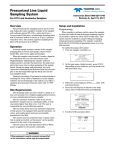
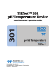
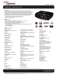
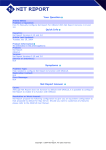
1640 Liquid Level
Actuator
Installation and Operation Guide
Part #60-1643-009
Copyright © 1976. All rights reserved, Teledyne Isco, Inc.
Revision H, May 2008
Foreword
This instruction manual is designed to help you gain a thorough understanding of the
operation of the equipment. Teledyne Isco recommends that you read this manual
completely before placing the equipment in service.
Although Teledyne Isco designs reliability into all equipment, there is always the possibility of a malfunction. This manual may help in diagnosing and repairing the malfunction.
If the problem persists, call or e-mail the Teledyne Isco Technical Service Department
for assistance. Simple difficulties can often be diagnosed over the phone.
If it is necessary to return the equipment to the factory for service, please follow the
shipping instructions provided by the Customer Service Department, including the
use of the Return Authorization Number specified. Be sure to include a note
describing the malfunction. This will aid in the prompt repair and return of the
equipment.
Teledyne Isco welcomes suggestions that would improve the information presented in
this manual or enhance the operation of the equipment itself.
Teledyne Isco is continually improving its products and reserves the right to
change product specifications, replacement parts, schematics, and instructions without notice.
Contact Information
Customer Service
Phone:
(800) 228-4373
(USA, Canada, Mexico)
(402) 464-0231
(Outside North America)
Fax:
(402) 465-3022
Email:
[email protected]
Technical Service
Phone:
Email:
(800) 775-2965
(Analytical)
(800) 228-4373
(Samplers and Flow Meters)
[email protected]
Return equipment to: 4700 Superior Street, Lincoln, NE 68504-1398
Other Correspondence
Mail to:
P.O. Box 82531, Lincoln, NE 68501-2531
Email:
[email protected]
Web site:
www.isco.com
Revised September 15, 2005
1640 Liquid Level Actuator
Table of Contents
Section 1 Introduction
1.1 Manual Organization . . . . . . . . . . . . . . . . . . . . . . . . . . . . . . . . . . . . . . . . . . . . . . . .
1.2 Description. . . . . . . . . . . . . . . . . . . . . . . . . . . . . . . . . . . . . . . . . . . . . . . . . . . . . . . . .
1.2.1 Control and Connector . . . . . . . . . . . . . . . . . . . . . . . . . . . . . . . . . . . . . . . . . .
1.2.2 Technical Specifications . . . . . . . . . . . . . . . . . . . . . . . . . . . . . . . . . . . . . . . .
1.3 Contacting Teledyne Isco . . . . . . . . . . . . . . . . . . . . . . . . . . . . . . . . . . . . . . . . . . . . .
1-1
1-1
1-2
1-2
1-2
Section 2 Operating Procedures
2.1 Connection to a Teledyne Isco Wastewater Sampler . . . . . . . . . . . . . . . . . . . . . . .
2.2 Mounting The Probe Assembly. . . . . . . . . . . . . . . . . . . . . . . . . . . . . . . . . . . . . . . . .
2.3 Operation . . . . . . . . . . . . . . . . . . . . . . . . . . . . . . . . . . . . . . . . . . . . . . . . . . . . . . . . . .
2.3.1 Latch . . . . . . . . . . . . . . . . . . . . . . . . . . . . . . . . . . . . . . . . . . . . . . . . . . . . . . . .
2.3.2 Toggle/Reset . . . . . . . . . . . . . . . . . . . . . . . . . . . . . . . . . . . . . . . . . . . . . . . . . .
2.4 Sampler Programming . . . . . . . . . . . . . . . . . . . . . . . . . . . . . . . . . . . . . . . . . . . . . . .
2.4.1 Programming LATCH Operation . . . . . . . . . . . . . . . . . . . . . . . . . . . . . . . . .
2.4.2 Programming TOGGLE Operation . . . . . . . . . . . . . . . . . . . . . . . . . . . . . . . .
2-1
2-2
2-3
2-3
2-3
2-3
2-3
2-4
Section 3 Construction
3.1 Mechanical Construction . . . . . . . . . . . . . . . . . . . . . . . . . . . . . . . . . . . . . . . . . . . . . 3-1
3.2 Description of the Electronic Circuitry . . . . . . . . . . . . . . . . . . . . . . . . . . . . . . . . . . 3-3
3.3 Routine Inspection and Care . . . . . . . . . . . . . . . . . . . . . . . . . . . . . . . . . . . . . . . . . . 3-4
iii
1640 Liquid Level Actuator
Table of Contents
iv
Section 1 Introduction
The first section of the 1640 instruction manual provides a
general introduction to the Liquid Level Sampler Actuator. It
includes a brief discussion of the organization of the manual, an
overall description of the 1640, including a listing of the controls
and connectors, a list of technical specifications, and information
for contacting the factory.
1.1 Manual Organization
The purpose of this manual is to assist the user in understanding
the operating procedures, maintenance, and basic construction of
the 1640 Liquid Level Sampler Actuator. To accomplish this
purpose, the manual is divided into three sections. The first
section provides a general introduction to the 1640. The second
section details procedures for setting up and operating the 1640.
The third section explains required routine inspection and care,
as well as the actuator’s physical construction.
1.2 Description
The Liquid Level Actuator is a device used in conjunction with an
Isco wastewater sampler to begin a sampling routine when the
liquid level reaches a predetermined height. Thc 1640 consists of
a control box assembly connected to the end of a 22 ft. coaxial
cable as shown in Figure 1-1. Refer to Table 1-2 for compatible
Teledyne Isco samplers.
Figure 1-1 1640 Liquid Level Sampler Actuator
1-1
1640 Liquid Level Actuator
Section 1 Introduction
1.2.1 Control and Connector
The control switch and connector of the 1640 are briefly
described in Table 1-1.
1.2.2 Technical
Specifications
Table 1-2 contains the technical specifications for the 1640.
Table 1-1 Control and Connector of the 1640
Control
Settings
Control Switch
Latch, Toggle/Reset
Connector
Function
Selects mode of 1640 operation; Latch
for latch mode and Toggle/Reset for toggle mode or for resetting the actuator.
Type
Sampler
6 Conductor Socket
Function
Power input from, and output signal to,
Teledyne Isco wastewater sampler.
Table 1-2 Technical Specifications of the 1640
Dimensions (Control Box)
Height: 2.92 in (7.4 cm)
Width: 1.38 in (3.5 cm)
Length: 2.25 (5.7cm)
Weight
1.0 lb. (453 gm)
Compatible Isco Samplers
3700 Series Portable and Refrigerated Samplers, 6700 Series Portable and
Refrigerated Samplers, GLS Compact Portable Sampler, Glacier Transportable Sampler, 6100 VOC Portable and Refrigerated Samplers
Output to Sampler
Open Collector
Power Required
12 VDC (Supplied by sampler)
Ambient Temperature Range
32°-120°F (0°-49°C)
1.3 Contacting Teledyne
Isco
Customer Service Department
P.O. Box 82531
Lincoln, NE 68501 USA
Phone:
(800) 228-4373
(402) 464-0231
FAX:(402) 465-3022
E-mail: [email protected]
1-2
1640 Liquid Level Actuator
Section 2 Operating Procedures
The second section of the 1640 instruction manual presents
detailed operating procedures for the Liquid Level Sampler
Actuator.
2.1 Connection to a
Teledyne Isco
Wastewater Sampler
This portion details the procedures which must be performed
before using the 1640. The 1640 comes with two velcro Dual
Lock™ fasteners - one permanently attached to the switch box,
the other with an adhesive strip for permanent attachment to
the sampler control box (Figure 2-2). Remove the backing from
the adhesive strip and press the assembly to the control box.
Make sure the sampler is off and connect the SAMPLER connector of the 1640 to the FLOW METER socket on the sampler.
Figure 2-1 1640 Liquid Level Actuator Installed on a Sampler
Figure 2-2 Dual Lock Fastener Attached to a Sampler
2-1
1640 Liquid Level Actuator
Section 2 Operating Procedures
2.2 Mounting The Probe
Assembly
Thc 1640 probe assembly should be rigidly mounted above the
flow stream using weather resistant hardware. The probe
assembly is connected to the control box by a 22 ft. cable, and
must be mounted within approximately 22 ft. of the sampler.
Figure 2-3 shows the probe assembly mounted on a stake using
the probe clamp supplied with the 1640. The probe is mounted
over the flow stream with the stainless steel pin pointing down
towards the liquid. The plastic rain deflector is positioned so that
it nearly covers the probe. The rain deflector prevents rain from
wetting the probe and accidentally actuating the sampler. It
should be kept clean on the inside. The vent hole in the side of
the rain deflector must be kept unobstructed so air can escape as
the liquid level rises inside of the rain deflector. The 1640 will
actuate the sampler when the liquid touches the stainless steel
ring inside of the rain deflector. Therefore the probe assembly
should be mounted with the stainless steel ring (not the probe
tip) positioned at the height where the sampler is to be actuated.
However, if the sampler is connected to a 117 VAC power pack,
the 1640 will actuate the sampler when the liquid touches the
probe tip.
Stake
(furnished by customer)
Clamp
Probe
Figure 2-3 Mounting the 1640 Probe Assembly
2-2
1640 Liquid Level Actuator
Section 2 Operating Procedures
2.3 Operation
The 1640 Liquid Level Sampler Actuator is switch-selectable for
either LATCH or TOGGLE/RESET operation. The following
paragraphs describe in detail both methods of operation.
2.3.1 Latch
When the switch is set to LATCH, the 1640 will actuate the
sampler when the liquid level rises to the stainless steel ring on
the probe assembly. The sampler remains actuated even if the
liquid level recedes.
2.3.2 Toggle/Reset
With the Liquid Level Actuator is set to TOGGLE/RESET the
sampler takes samples only while the liquid is touching the
probe assembly. When the liquid level rises to the probe assembly
the 1640 actuates the sampler. The sampler will continue taking
samples only as long as the liquid touches the stainless steel
ring. If the liquid level recedes, the sampler will be inhibited
until the liquid level again rises to the probe assembly. If the
liquid level recedes while the sampler is taking a sample, it will
finish taking the sample before shutting off.
The TOGGLE/RESET switch selection is also used to reset the
Liquid Level Actuator.
2.4 Sampler
Programming
2.4.1 Programming LATCH
Operation
You must configure the sampler to respond to the actuator. Information on programming the sampler for use with the actuator
can be found in the discussion of the ENABLE PIN or SAMPLER
ENABLE configure option in the sampler’s manual. All Isco samplers can be used in either the Time or Flow mode when used in
conjunction with the 1640. If the Flow mode is used, a “Y”
connect cable (Isco part #60-3004-019) will be necessary to
connect both the 1640 and the flow meter to the FLOW METER
port on the sampler.
To program the sampler and 1640 when the actuator is set to
LATCH, the following set of instructions is recommended.
1. Program the sampler for the time interval or number of
flow pulses between samples following the instructions
given in the sampler’s manual.
2. Momentarily set the 1640 CONTROL switch to the TOGGLE/RESET position to reset the actuator.
3. Set the CONTROL switch to the LATCH position.
When first actuated, the sampler will immediately take a
sample, if the time period from when the sampler and actuator
were turned on to when the liquid level reaches the probe
assembly is greater than one time period between samples (as
programmed on the sampler). The sampler will then return to its
prescribed time base and take samples at the programmed time
intervals. If, after the sampler and 1640 have been turned on, the
liquid level rises to the probe before one time interval between
samples (as programmed on the sampler) has passed, the
sampler will wait until the end of the first time interval to take
the first sample. Thereafter, it will take samples as programmed.
For example: The 1640 is set to LATCH and the sampler is
turned on at 4:00. The sampler is programmed to take a sample
2-3
1640 Liquid Level Actuator
Section 2 Operating Procedures
every hour on the hour. At 6:20 (more than one time interval
between samples has passed) the liquid level rises to the probe,
and the 1640 actuates the sampler. The sampler then takes the
first sample at 6:20, the second at 7:00, the third at 8:00, etc. and
continues taking samples every hour until it completes it’s entire
program. However, if the sampler is turned on at 4:00 and the
liquid level rises to the probe at 4:20 (less than one time interval
between samples has passed), then the sampler will take the
first sample at 5:00, the second at 6:00, the third at 7:00, etc.
until it has completed it’s entire program.
2.4.2 Programming TOGGLE
Operation
To program the sampler and 1640 when the actuator is set to
TOGGLE/RESET, the following set of instructions is recommended.
1. Program the sampler for the time interval or number of
flow pulses between samples following the instructions
given in the sampler’s manual.
2. Set the 1640 CONTROL switch to the TOGGLE/RESET
position.
When the liquid level rises to the probe assembly, the 1640
actuates the sampler. The sampler will react just as it does in the
LATCH setting. However, the sampler will continue taking
samples only as long as the liquid level touches the stainless
steel ring.
2-4
1640 Liquid Level Actuator
Section 3 Construction
This section of the 1640 instruction manual presents a basic
description of the mechanical and electronic construction of the
1640 Liquid Level Sampler Actuator in order to provide background information which may be necessary for special applications.
Note
The Liquid Level Actuator is not serviceable in the field. If
replacement of parts becomes necessary, contact Teledyne
Isco.
3.1 Mechanical
Construction
The 1640 is constructed to be extremely weather resistant and
watertight. The electronic circuitry is placed inside of the control
box which is then filled with an epoxy potting compound. The
CONTROL switch is protected by a water resistant boot. Thus,
the electronic circuitry is made immune to moisture and dust.
The actuator hold-down, the probe tip, and the probe ring are all
made of stainless steel for corrosion resistance and strength. The
probe assembly is mounted on the end of a 22 ft. coaxial cable.
The center conductor is terminated by the stainless steel pin.
The stainless steel ring is crimped over the outer conductor. The
probe is then covered by a plastic rain deflector which protects it
from rain and other unwanted moisture. This ensures that the
sampler will not be actuated accidently. The rain deflector has a
vent hole which must be unobstructed so that air can escape from
the interior of the deflector as the liquid level rises.
The 1640’s individual parts are identified in Figure 3-1.
3-1
1640 Liquid Level Actuator
Section 3 Construction
Figure 3-1 1640 Liquid Level Actuator, Assembly #60-1644-000
ID No.
Description
1
Probe Clamp (not shown)
2
Switch Boot N-5030L
3
Rain Deflector
4
Probe Sleeve
5
Cable Termination Pin
6
“Y” Connect Cable - Sampler/Flow
Meter/1640 (not shown)
Part #60-3004-019
7
Dual Lock Fastener #170
Part #60-3703-123
8
Dual Lock Fastener #400
Part #60-3703-114
3-2
1640 Liquid Level Actuator
Section 3 Construction
3.2 Description of the
Electronic Circuitry
Although the electronic circuitry is enclosed in an epoxy potting
compound and is inaccessible, a description of the circuitry is
included in order to provide background information which
might be needed for special applications. Refer to Figure 3-2, the
1640 schematic diagram. Placing the CONTROL switch in the
TOGGLE/RESET position resets the circuit insuring that it is
not actuating the sampler. This sets the output of UlA to its HI
state, causing the 2N3704 (Q1) transistor to conduct. Thus, while
the probe assembly is out of the liquid, the transistor and the 100
ohm resistor act as a current sink. When the probe assembly is
not in the liquid, the input of U1D is set HI. However, when the
liquid rises until it covers both the probe and the stainless steel
ring a current will flow from the pin to the ring causing the input
to U1D to become LO. Consequently, the output of UlA becomes
LO, which shuts off the transistor. This actuates the sampler. If
the CONTROL switch is in the TOGGLE/RESET position, the
transistor will remain off only while liquid is covering the probe
assembly. If the liquid level recedes, the transistor will again
conduct, which inhibits the sampler from taking samples.
However, if the CONTROL switch is in the LATCH position
when the liquid first rises to the probe assembly, the output of
U1A will latch to the LO state. This will shut off the transistor
(and actuate the sampler) until the CONTROL switch is again
set to the TOGGLE/RESET position.
C
D
B
A
Figure 3-2 1640 Schematic Diagram
Note
If the sampler is connected to a 117 VAC power pack, it will be
actuated when the liquid first touches the stainless steel pin
rather than when it touches the stainless steel ring. This
occurs because the 117 VAC power pack has an earth ground.
Thus when the liquid touches the stainless steel pin a current
will flow from the pin to the earth causing the input to U1D to
become LO which actuates the sampler.
3-3
1640 Liquid Level Actuator
Section 3 Construction
3.3 Routine Inspection
and Care
The 1640 probe assembly should be periodically inspected for
cracks in the rain deflector, and for loosening of the stainless
steel pin and/or ring. If any of these conditions occur the
respective parts should be replaced. The interior of the rain
deflector must be kept clean and free from debris, and the vent
hole must be free of obstructions. Under normal conditions,
simply wiping the probe assembly off will suffice. If heavy
deposits build up on the probe assembly, it may be cleaned with a
soapy solution.
Note
The Liquid Level Actuator is not serviceable in the field. If
replacement of parts becomes necessary, contact Teledyne
Isco.
3-4
Warranty
Teledyne Isco One Year
Limited Factory Service Warranty *
Teledyne Isco warrants covered products
against failure due to faulty parts or
workmanship for a period of one year (365
days) from their shipping date, or from the
date of installation by an authorized Teledyne
Isco Service Engineer, as may be appropriate.
During the warranty period, repairs,
replacements, and labor shall be provided at
no charge. Teledyne Isco’s liability is strictly
limited to repair and/or replacement, at
Teledyne Isco’s sole discretion.
Failure of expendable items (e.g., charts,
ribbon, tubing, lamps, glassware, seals,
filters, fittings, and wetted parts of valves), or
from normal wear, accident, misuse,
corrosion, or lack of proper maintenance, is
not covered. Teledyne Isco assumes no
liability for any consequential damages.
This warranty does not cover loss, damage,
or defects resulting from transportation
between the customer’s facility and the repair
facility.
Teledyne Isco specifically disclaims any
warranty of merchantability or fitness for a
particular purpose.
This warranty applies only to products sold
under the Teledyne Isco trademark and is
made in lieu of any other warranty, written or
expressed.
No items may be returned for warranty
service without a return authorization number
issued from Teledyne Isco.
The warrantor is Teledyne Isco, Inc.
4700 Superior, Lincoln, NE 68504, U.S.A.
* This warranty applies to the USA and countries where Teledyne Isco Inc. does not have an authorized dealer. Customers in countries outside
the USA, where Teledyne Isco has an authorized dealer, should contact their Teledyne Isco dealer for warranty service.
In the event of instrument problems, always contact the Teledyne Isco Service Department, as problems can
often be diagnosed and corrected without requiring an on-site visit. In the U.S.A., contact Teledyne Isco Service
at the numbers listed below. International customers should contact their local Teledyne Isco agent or Teledyne
Isco International Customer Service.
Return Authorization
A return authorization number must be issued prior to shipping. Following authorization,
Teledyne Isco will pay for surface transportation (excluding packing/crating) both ways for 30
days from the beginning of the warranty period. After 30 days, expense for warranty shipments
will be the responsibility of the customer.
Shipping Address:
Mailing address:
Phone:
Fax:
Email:
February 1, 2006 P/N 60-1002-040 Rev C
Teledyne Isco, Inc. - Attention Repair Service
4700 Superior Street
Lincoln NE 68504 USA
Teledyne Isco, Inc.
PO Box 82531
Lincoln NE 68501 USA
Repair service: (800)775-2965 (lab instruments)
(800)228-4373 (samplers & flow meters)
Sales & General Information (800)228-4373 (USA & Canada)
(402) 465-3001
[email protected]
Web site: www.isco.com