1
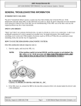
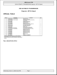
2004 Acura TSX
2004 ENGINE PERFORMANCE Fuel & Emissions Systems - TSX
2004 ENGINE PERFORMANCE
Fuel & Emissions Systems - TSX
SPECIAL TOOLS
Fig. 1: Special Tools (1 Of 2)
Fig. 2: Special Tools (2 Of 2)
GENERAL TROUBLESHOOTING INFORMATION
Wednesday, March 12, 2008 2:06:18
2:05:56 AM
Page 1
2004 Acura TSX
2004 ENGINE PERFORMANCE Fuel & Emissions Systems - TSX
INTERMITTENT FAILURES
The term "intermittent failure" means a system may have had a failure, but it checks OK now. If the
malfunction indicator lamp (MIL) on the dash does not come on, check for poor connections or loose pins at all
connectors related to the circuit that you are troubleshooting.
OPENS & SHORTS
"Open" and "Short" are common electrical terms. An open is a break in a wire or at a connection. A short is an
accidental connection of a wire to ground or to another wire. In simple electronics, this usually means
something won't work at all. With complex electronics (such as ECMs and PCMs) this can sometimes mean
something works, but not the way it's supposed to.
HOW TO USE THE HDS (HONDA DIAGNOSTIC SYSTEM)
If the MIL (Malfunction Indicator Lamp) has come on
1. Start the engine and check the MIL (A).
NOTE:
If the ignition switch is turned ON (II), and the engine is not started, the
MIL will stay on for 15-20 seconds (see HOW TO SET READINESS
CODES ).
Wednesday, March 12, 2008 2:05:56 AM
Page 2
2004 Acura TSX
2004 ENGINE PERFORMANCE Fuel & Emissions Systems - TSX
Fig. 3: Identifying MIL (Malfunction Indicator Lamp)
2. If the MIL stays on, connect the HDS to the data link connector (DLC) (A) located under the driver's side
of the dashboard.
Wednesday, March 12, 2008 2:05:56 AM
Page 3
2004 Acura TSX
2004 ENGINE PERFORMANCE Fuel & Emissions Systems - TSX
Fig. 4: Connecting The HDS To The Data Link Connector (DLC) Located Under The Driver's Side
Of The Dashboard
3. Turn the ignition switch ON (II).
4. Check the diagnostic trouble code (DTC) and note it. Also check the freeze data. Refer to the DTC
Troubleshooting Index and begin the appropriate troubleshooting procedure.
NOTE:
z
z
z
Freeze data indicates the engine conditions when the first
malfunction, misfire, or fuel trim malfunction was detected.
The HDS can read the DTC, freeze data, current data, and other
engine control module (ECM)/powertrain control module (PCM) data.
For specific operations, refer to the user's manual that came with the
HDS.
5. If no DTC are found, go to MIL troubleshooting (see MIL CIRCUIT TROUBLESHOOTING ).
If the MIL did not stay on
Wednesday, March 12, 2008 2:05:56 AM
Page 4
2004 Acura TSX
2004 ENGINE PERFORMANCE Fuel & Emissions Systems - TSX
If the MIL did not stay on but there is a driveability problem, refer to the Symptom Troubleshooting Index in
this section.
If you can't duplicate the DTC
Some of the troubleshooting requires you to reset the ECM/PCM and try to duplicate the DTC. If the problem is
intermittent and you can't duplicate the code, do not continue through the procedure. To do so will only result in
confusion and, possibly, a needlessly replaced ECM/PCM.
HDS CLEAR COMMAND
The ECM/PCM stores various specific data to correct the system even when there is no electrical power such as
the battery negative terminal or No. 8 FI ECU (ECM/PCM) (15A) fuse are disconnected. Stored data based on
failed parts should be cleared by using the "CLEAR COMMAND" of the HDS, if parts are replaced.
The HDS has three kinds of clear commands to meet the purpose. They are DTC clear, ECM/PCM clear, and
CKP pattern clear. DTC clear command erases all stored DTC codes, freeze data and readiness codes. This must
be done with the HDS after reproducing the DTC during troubleshooting in this service manual.
ECM/PCM clear command erases all stored DTC codes, freeze data, readiness codes, and all specific data to
correct the system except CKP pattern. If the CKP pattern data in ECM/PCM was cleared, you must do the
CKP pattern learn procedure. The CKP pattern clear command erases only CKP pattern data. This command is
for the repair of a misfire or CKP sensor.
DTC CLEAR
1.
2.
3.
4.
Do the DTC CLEAR in the CLEAR MENU with the HDS while the engine is stopped.
Turn the ignition switch OFF.
Turn the ignition switch ON (II). Wait for 30 seconds.
Turn the ignition switch OFF, and disconnect the HDS from the DLC.
ECM/PCM RESET
This command clears stored specific data from each vehicle such as DTCs freeze data, and readiness codes. It
does not clear CKP PATTERN data.
1.
2.
3.
4.
5.
Do the ECM/PCM RESET in the CLEAR MENU with the HDS while the engine is stopped.
Turn the ignition switch OFF.
Turn the ignition switch ON (II). Wait for 30 seconds.
Turn the ignition switch OFF, and disconnect the HDS from the DLC.
Do the ECM/PCM idle learn procedure (see ECM/PCM IDLE LEARN PROCEDURE ).
CKP PATTERN CLEAR/CKP PATTERN LEARN PROCEDURE
Enable Criteria
Wednesday, March 12, 2008 2:05:56 AM
Page 5
2004 Acura TSX
2004 ENGINE PERFORMANCE Fuel & Emissions Systems - TSX
ECT at 176°F (80°C) or higher.
Procedure
1.
2.
3.
4.
Do the CKP PATTERN CLEAR in the CLEAR MENU with the HDS while the engine is stopped.
Turn the ignition OFF.
Turn the ignition ON (II), and wait for 30 seconds.
Test-drive the vehicle on a level road: Decelerate (with the throttle fully closed) from engine speed of
2,500 RPM to 1,000 RPM with the A/T in 2 position, or the M/T in 2nd or 3rd gear.
5. Stop the vehicle. Do not turn the ignition off.
6. Select the ALL DATA LIST in the DATA LIST MENU of the HDS.
7. Check the status of PULSER F/B LEARN. If it is set to NG, the enable criteria was probably not met;
repeat the procedure from the beginning.
HOW TO END A TROUBLESHOOTING SESSION (REQUIRED AFTER ANY
TROUBLESHOOTING)
1.
2.
3.
4.
Do the ECM/PCM RESET in the CLEAR MENU with the HDS.
Do the ECM/PCM idle learn procedure (see ECM/PCM IDLE LEARN PROCEDURE ).
Turn the ignition switch OFF.
Disconnect the HDS from the DLC.
NOTE:
The ECM/PCM is part of the immobilizer system. If you replace the ECM/PCM, it
will have a different immobilizer code. In order for the engine to start, you must
rewrite the immobilizer code with the HDS.
HOW TO REMOVE THE ECM/PCM FOR TESTING
If DTC troubleshooting requires voltage or resistance checks at the ECM/PCM connectors, remove the
ECM/PCM and test it.
1. Jump the SCS line with the HDS.
2. Remove the center lower covers (A).
Wednesday, March 12, 2008 2:05:57 AM
Page 6
2004 Acura TSX
2004 ENGINE PERFORMANCE Fuel & Emissions Systems - TSX
Fig. 5: Removing The ECM/PCM
3.
4.
5.
6.
7.
Remove the duct (B).
Disconnect the ECM/PCM connectors (C).
Remove the bolts (D), then remove the ECM/PCM (E).
Install the ECM/PCM in the reverse order of removal.
Open the SCS line with the HDS.
HOW TO TROUBLESHOOT CIRCUITS AT THE ECM/PCM
Special Tools Required:
Wednesday, March 12, 2008 2:05:57 AM
Page 7
2004 Acura TSX
2004 ENGINE PERFORMANCE Fuel & Emissions Systems - TSX
z
z
Digital Multimeter KS-AHM-32-003 (1) or a commercially available digital multimeter
Backprobe Set 07SAZ-001000A (2)
1. Connect the backprobe adapters (A) to the stacking patch cords (B), and connect the cords to a digital
multimeter.
Fig. 6: Connecting The Backprobe Adapters To The Stacking Patch Cords & The Cords To A
Digital Multimeter
2. Using the wire insulation as a guide for the contoured tip of the backprobe adapter, gently slide the tip
into the connector from the wire side until it touches the end of the wire terminal.
Wednesday, March 12, 2008 2:05:57 AM
Page 8
2004 Acura TSX
2004 ENGINE PERFORMANCE Fuel & Emissions Systems - TSX
3. If you cannot get to the wire side of the connector or the wire side is sealed (A), disconnect the connector
and probe the terminals (B) from the terminal side. Do not force the probe into the connector.
NOTE:
Do not puncture the insulation on a wire. Punctures can cause poor or
intermittent electrical connections.
Fig. 7: Do Not Force The Probe Into The Connector
ECM/PCM UPDATING AND SUBSTITUTION FOR TESTING
Special Tools Required: Honda Interface Module (HIM) EQS05A35570
Use this procedure when you have to substitute a known-good ECM/PCM in a troubleshooting procedure.
Update the ECM/PCM only if the ECM/PCM does not have the latest software loaded.
NOTE:
Do not turn the ignition switch OFF while updating the ECM/PCM. If you turn the
ignition switch OFF before completion, the ECM/PCM can be damaged.
HOW TO UPDATE THE ECM/PCM
NOTE:
z
z
To ensure the latest program is installed, do an ECM/PCM update
whenever the ECM/PCM is substituted or replaced.
You can not update an ECM/PCM with the program it already has. It will
only accept a new program.
Wednesday, March 12, 2008 2:05:57 AM
Page 9
2004 Acura TSX
2004 ENGINE PERFORMANCE Fuel & Emissions Systems - TSX
z
z
z
Before you update the ECM/PCM, make sure the vehicle's battery is fully
charged.
To prevent ECM/PCM damage, do not operate anything electrical (audio
system, brakes, A/C, power windows, moonroof, door locks, etc.) during
the update.
If you need to diagnose the Honda Interface Module (HIM) because the
HIM's red (#3) light came on or was flashing during the update, leave the
ignition switch in the ON (II) position when you disconnect the HIM from
the data link connector (DLC). This will prevent ECM/PCM damage.
1. Turn the ignition switch ON (II). Do not start the engine.
2. Connect the HDS or the Honda Interface Module (HIM) to the data link connector (DLC) (A) located
under the driver's side of the dashboard.
Fig. 8: Connecting The HDS Or HIM To The Data Link Connector (DLC) Located Under The
Driver's Side Of The Dashboard
Wednesday, March 12, 2008 2:05:57 AM
Page 10
2004 Acura TSX
2004 ENGINE PERFORMANCE Fuel & Emissions Systems - TSX
3. Do the ECM/PCM update procedure as described on the HIM label and in the ECM/PCM update system.
4. Do the ECM/PCM idle learn procedure (see ECM/PCM IDLE LEARN PROCEDURE ).
5. Do the CKP pattern learn procedure, if you did the troubleshooting for DTC P0300, P0301, P0302,
P0303, P0304, P0335 or P0339.
HOW TO SUBSTITUTE THE ECM/PCM
1. Remove the ECM/PCM form the vehicle.
2. Install a known-good ECM/PCM.
3. Rewrite the immobilizer code with the ECM/PCM replacement procedure in the HDS; it allows you to
start the engine.
4. After completing your tests, install the original ECM/PCM and rewrite the immobilizer code with the
ECM/PCM replacement procedure in the HDS.
OBD STATUS
The OBD status shows the current system status of each DTC and all of the parameters. This function is used to
see if the technician's repair was successfully finished. The results of diagnostic tests for the DTC are displayed
as:
z
z
z
z
z
PASSED: On board diagnosis is successfully finished.
FAILED: On board diagnosis has finished but failed.
EXECUTING: The vehicle is in enable criteria conditions for the DTC and the on board diagnosis is
running.
NOT COMPLETED: The on board diagnosis was running but is out of the enable conditions of the
DTC.
OUT of COND: The vehicle has stayed out of the enable conditions of the DTC.
DTC TROUBLESHOOTING INDEX
Wednesday, March 12, 2008 2:05:57 AM
Page 11
2004 Acura TSX
2004 ENGINE PERFORMANCE Fuel & Emissions Systems - TSX
Fig. 9: DTC Troubleshooting Index (1 Of 3)
Wednesday, March 12, 2008 2:05:57 AM
Page 12
2004 Acura TSX
2004 ENGINE PERFORMANCE Fuel & Emissions Systems - TSX
Fig. 10: DTC Troubleshooting Index (2 Of 3)
Wednesday, March 12, 2008 2:05:57 AM
Page 13
2004 Acura TSX
2004 ENGINE PERFORMANCE Fuel & Emissions Systems - TSX
Fig. 11: DTC Troubleshooting Index (3 Of 3)
SYMPTOM TROUBLESHOOTING INDEX
When the vehicle has one of these symptoms, check for a diagnostic trouble code (DTC) with the scan tool. If
there is no DTC, do the diagnostic procedure for the symptom, in the sequence listed, until you find the cause.
Wednesday, March 12, 2008 2:05:57 AM
Page 14
2004 Acura TSX
2004 ENGINE PERFORMANCE Fuel & Emissions Systems - TSX
Fig. 12: Symptom Troubleshooting Index (1 Of 2)
Fig. 13: Symptom Troubleshooting Index (2 Of 2)
SYSTEM DESCRIPTIONS
Wednesday, March 12, 2008 2:05:57 AM
Page 15
2004 Acura TSX
2004 ENGINE PERFORMANCE Fuel & Emissions Systems - TSX
ELECTRONIC CONTROL SYSTEM
The functions of the fuel and emission control systems are managed by the engine control module (ECM) on
vehicles with manual transmissions or the powertrain control module (PCM) on vehicles with automatic
transmissions.
FAIL-SAFE FUNCTION
When an abnormality occurs in the signal from a sensor, the ECM/PCM ignores that signal and assumes a
preprogrammed value for the sensor that allows the engine to continue to run.
BACK-UP FUNCTION
When an abnormality occurs in the ECM/PCM, the injectors are controlled by a back-up circuit independent of
the system to permit minimal driving.
SELF-DIAGNOSIS
When an abnormality occurs in the signal from a sensor, the ECM/PCM supplies ground for the malfunction
indicator lamp (MIL) and stores the diagnostic trouble code (DTC) in erasable memory. When the ignition is
first turned on, the ECM/PCM supplies ground to the MIL for 15 to 20 seconds to check the MIL bulb
condition. If all readiness code are not set, the MIL will flash five times. If readiness codes are set to complete,
the MIL will go out.
TWO DRIVING CYCLE DETECTION METHOD
To prevent false indications, the "two driving cycle detection method" is used for some self-diagnostic
functions. When an abnormality occurs, the ECM/PCM stores it in its memory. When the same abnormality
recurs after the ignition switch is turned OFF and ON (II) again, the ECM/PCM turns on the MIL.
SELF SHUT DOWN MODE (SSD)
After the ignition switch is turned off, the ECM/PCM stays ON (up to 15 minutes). If the ECM/PCM connector
is disconnected during this mode, the ECM/PCM may be damaged. To cancel this mode, disconnect the
negative cable from the battery or jump the SCS line with the HDS after the key is turned off.
ECM/PCM ELECTRICAL CONNECTIONS
Wednesday, March 12, 2008 2:05:57 AM
Page 16
2004 Acura TSX
2004 ENGINE PERFORMANCE Fuel & Emissions Systems - TSX
Fig. 14: ECM/PCM Wiring Diagram (1 Of 5)
Wednesday, March 12, 2008 2:05:57 AM
Page 17
2004 Acura TSX
2004 ENGINE PERFORMANCE Fuel & Emissions Systems - TSX
Fig. 15: ECM/PCM Wiring Diagram (2 Of 5)
Wednesday, March 12, 2008 2:05:57 AM
Page 18
2004 Acura TSX
2004 ENGINE PERFORMANCE Fuel & Emissions Systems - TSX
Fig. 16: ECM/PCM Wiring Diagram (3 Of 5)
Wednesday, March 12, 2008 2:05:57 AM
Page 19
2004 Acura TSX
2004 ENGINE PERFORMANCE Fuel & Emissions Systems - TSX
Fig. 17: ECM/PCM Wiring Diagram (4 Of 5)
Wednesday, March 12, 2008 2:05:57 AM
Page 20
2004 Acura TSX
2004 ENGINE PERFORMANCE Fuel & Emissions Systems - TSX
Fig. 18: ECM/PCM Wiring Diagram (5 Of 5)
ECM/PCM INPUTS & OUTPUTS AT CONNECTOR A (31P)
Wednesday, March 12, 2008 2:05:57 AM
Page 21
2004 Acura TSX
2004 ENGINE PERFORMANCE Fuel & Emissions Systems - TSX
Fig. 19: Identifying ECM/PCM Connector A (31P) Terminals
NOTE:
Standard battery voltage is 12 V.
Fig. 20: ECM/PCM Connector A (31P) Pin Voltage Chart (1 Of 2)
Wednesday, March 12, 2008 2:05:57 AM
Page 22
2004 Acura TSX
2004 ENGINE PERFORMANCE Fuel & Emissions Systems - TSX
Fig. 21: ECM/PCM Connector A (31P) Pin Voltage Chart (2 Of 2)
ECM/PCM INPUTS & OUTPUTS AT CONNECTOR B (24P)
Fig. 22: Identifying ECM/PCM Connector B (24P) Terminals
NOTE:
Standard battery voltage is 12 V.
Wednesday, March 12, 2008 2:05:57 AM
Page 23
2004 Acura TSX
2004 ENGINE PERFORMANCE Fuel & Emissions Systems - TSX
Fig. 23: ECM/PCM Connector B (24P) Pin Voltage Chart
PCM INPUTS & OUTPUTS AT CONNECTOR C (22P)
Wednesday, March 12, 2008 2:05:57 AM
Page 24
2004 Acura TSX
2004 ENGINE PERFORMANCE Fuel & Emissions Systems - TSX
Fig. 24: Identifying ECM/PCM Connector C (22P) Terminals
NOTE:
Standard battery voltage is 12 V.
Wednesday, March 12, 2008 2:05:57 AM
Page 25
2004 Acura TSX
2004 ENGINE PERFORMANCE Fuel & Emissions Systems - TSX
Fig. 25: ECM/PCM Connector C (22P) Pin Voltage Chart (1 Of 2)
Fig. 26: ECM/PCM Connector C (22P) Pin Voltage Chart (2 Of 2)
ECM/PCM INPUTS & OUTPUTS AT CONNECTOR D (17P)
Wednesday, March 12, 2008 2:05:57 AM
Page 26
2004 Acura TSX
2004 ENGINE PERFORMANCE Fuel & Emissions Systems - TSX
Fig. 27: Identifying ECM/PCM Connector D (17P) Terminals
NOTE:
Standard battery voltage is 12 V.
Wednesday, March 12, 2008 2:05:57 AM
Page 27
2004 Acura TSX
2004 ENGINE PERFORMANCE Fuel & Emissions Systems - TSX
Fig. 28: ECM/PCM Connector D (17P) Pin Voltage Chart
ECM/PCM INPUTS & OUTPUTS AT CONNECTOR E (31P)
Fig. 29: Identifying ECM/PCM Connector E (31P) Terminals
NOTE:
Standard battery voltage is 12 V.
Wednesday, March 12, 2008 2:05:57 AM
Page 28
2004 Acura TSX
2004 ENGINE PERFORMANCE Fuel & Emissions Systems - TSX
Fig. 30: ECM/PCM Connector E (31P) Pin Voltage Chart (1 Of 2)
Fig. 31: ECM/PCM Connector E (31P) Pin Voltage Chart (2 Of 2)
Wednesday, March 12, 2008 2:05:57 AM
Page 29
2004 Acura TSX
2004 ENGINE PERFORMANCE Fuel & Emissions Systems - TSX
VACUUM HOSE ROUTING
Fig. 32: Vacuum Hose Routing
VACUUM DISTRIBUTION
Wednesday, March 12, 2008 2:05:57 AM
Page 30
2004 Acura TSX
2004 ENGINE PERFORMANCE Fuel & Emissions Systems - TSX
Fig. 33: Vacuum Distribution
PGM-FI SYSTEM
The Programmed Fuel Injection (PGM-FI) system is a sequential multiport fuel injection system.
AIR CONDITIONING (A/C) COMPRESSOR CLUTCH RELAY
When the ECM/PCM receives a demand for cooling from the A/C system, it delays the compressor from being
Wednesday, March 12, 2008 2:05:57 AM
Page 31
2004 Acura TSX
2004 ENGINE PERFORMANCE Fuel & Emissions Systems - TSX
energized, and enriches the mixture to assure smooth transition to the A/C mode.
AIR FUEL RATIO (A/F) SENSOR
The A/F Sensor operates over a wide air/fuel range. The A/F Sensor is installed upstream of the TWC, and
sends signals to the ECM/PCM which varies the duration of fuel injection accordingly.
Fig. 34: Identifying Air Fuel Ratio (A/F) Sensor
BAROMETRIC PRESSURE (BARO) SENSOR
The BARO sensor is inside the ECM/PCM. It converts atmospheric pressure into a voltage signal that modifies
the basic duration of the fuel injection discharge.
CAMSHAFT POSITION (CMP) SENSOR B
CMP sensor B detects the position of the No. 1 cylinder as a reference for sequential fuel injection to each
cylinder.
Wednesday, March 12, 2008 2:05:57 AM
Page 32
2004 Acura TSX
2004 ENGINE PERFORMANCE Fuel & Emissions Systems - TSX
Fig. 35: Cutaway View Of Camshaft Position (CMP) Sensor B
COUNTERSHAFT SPEED SENSOR
This sensor detects countershaft speed.
Wednesday, March 12, 2008 2:05:57 AM
Page 33
2004 Acura TSX
2004 ENGINE PERFORMANCE Fuel & Emissions Systems - TSX
Fig. 36: Cutaway View Of Countershaft Speed Sensor
CRANKSHAFT POSITION (CKP) SENSOR
The CKP sensor detects crankshaft speed and is used by the ECM/PCM to determine ignition timing and timing
for fuel injection of each cylinder as well as detecting engine misfire.
Wednesday, March 12, 2008 2:05:57 AM
Page 34
2004 Acura TSX
2004 ENGINE PERFORMANCE Fuel & Emissions Systems - TSX
Fig. 37: Cutaway View Of Crankshaft Position (CKP) Sensor
ENGINE COOLANT TEMPERATURE (ECT) SENSOR
The ECT sensor is a temperature dependent resistor (thermistor). The resistance of the thermistor decreases as
the engine coolant temperature increases.
Wednesday, March 12, 2008 2:05:57 AM
Page 35
2004 Acura TSX
2004 ENGINE PERFORMANCE Fuel & Emissions Systems - TSX
Fig. 38: Cutaway View Of Engine Coolant Temperature (ECT) Sensor
IGNITION TIMING CONTROL
The ECM/PCM contains the memory for basic ignition timing at various engine speeds and manifold absolute
pressure. It also adjusts the timing according to engine coolant temperature and intake air temperature.
INJECTOR TIMING & DURATION
The ECM/PCM contains the memory for basic discharge duration at various engine speeds and manifold
pressures. The basic discharge duration, after being read out from the memory, is further modified by signals
sent from various sensors to obtain the final discharge duration.
By monitoring long term fuel trim, the ECM/PCM detects long term malfunctions in the fuel system and sets a
diagnostic trouble code (DTC).
INTAKE AIR TEMPERATURE (IAT) SENSOR
The IAT sensor is a temperature dependent resistor (thermistor). The resistance of the thermistor decreases as
the intake air temperature increases.
Wednesday, March 12, 2008 2:05:57 AM
Page 36
2004 Acura TSX
2004 ENGINE PERFORMANCE Fuel & Emissions Systems - TSX
Fig. 39: Cutaway View Of Intake Air Temperature (IAT) Sensor
KNOCK SENSOR
The knock control system adjusts the ignition timing to minimize knock.
Wednesday, March 12, 2008 2:05:57 AM
Page 37
2004 Acura TSX
2004 ENGINE PERFORMANCE Fuel & Emissions Systems - TSX
Fig. 40: Cutaway View Of Knock Sensor
MALFUNCTION INDICATOR LAMP (MIL) INDICATION (IN RELATION TO READINESS
CODES)
The vehicle has certain "readiness codes" that are part of the on-board diagnostics for the emissions systems. If
the vehicle's battery has been disconnected or gone dead, if the DTCs have been cleared, or if the ECM/PCM
has been reset, these codes are reset. In some states, part of the emissions testing is to make sure these codes are
set to complete. If all of them are not set to complete, the vehicle may fail the test, or the test cannot be finished.
To check if the readiness codes are set to complete, turn the ignition switch ON (II), but do not start the engine.
The MIL will come on for 15-20 seconds. If it then goes off, the readiness codes are complete. If it flashes five
Wednesday, March 12, 2008 2:05:57 AM
Page 38
2004 Acura TSX
2004 ENGINE PERFORMANCE Fuel & Emissions Systems - TSX
times, one or more readiness codes are not complete. To set each code, drive the vehicle or run the engine as
described in the procedures in this section (see HOW TO SET READINESS CODES ).
MANIFOLD ABSOLUTE PRESSURE (MAP) SENSOR
The MAP sensor converts manifold absolute pressure into electrical signals to the ECM/PCM.
Fig. 41: Cutaway View Of Manifold Absolute Pressure (MAP) Sensor
SECONDARY HEATED OXYGEN SENSOR (SECONDARY HO2S)
The secondary HO2S detects the oxygen content in the exhaust gas downstream of the three way catalytic
converter (TWC), and sends signals to the ECM/PCM which varies the duration of fuel injection accordingly.
To stabilize its output, the sensor has an internal heater. The ECM/PCM compares the HO2S output with the
A/F sensor output to determine catalyst efficiency. The secondary HO2S is located on the TWC.
Wednesday, March 12, 2008 2:05:57 AM
Page 39
2004 Acura TSX
2004 ENGINE PERFORMANCE Fuel & Emissions Systems - TSX
Fig. 42: Cutaway View Of Secondary Heated Oxygen Sensor (Secondary HO2S)
ELECTRONIC THROTTLE CONTROL SYSTEM
The throttle is electronically controlled by the electronic throttle control system. Refer to the System Diagram to
see the functional layout of the system.
Idle Control: When the engine is idling, the ECM/PCM controls the throttle actuator to maintain the proper
idle speed according to engine loads.
Acceleration Control: When the accelerator pedal is pressed, the ECM/PCM opens the throttle valve
depending on the accelerator pedal position (APP) sensor signal.
Cruise Control: The ECM/PCM controls the throttle actuator to maintain set speed when the cruise control is
operating. The throttle actuator takes the place of the cruise control actuator.
ACCELERATOR PEDAL POSITION (APP) SENSOR
As the accelerator pedal position changes, the sensor varies the signal voltage to the ECM/PCM.
Wednesday, March 12, 2008 2:05:57 AM
Page 40
2004 Acura TSX
2004 ENGINE PERFORMANCE Fuel & Emissions Systems - TSX
Fig. 43: Locating Accelerator Pedal Position (APP) Sensor
Wednesday, March 12, 2008 2:05:57 AM
Page 41
2004 Acura TSX
2004 ENGINE PERFORMANCE Fuel & Emissions Systems - TSX
Fig. 44: Cutaway View Of Accelerator Pedal Position (APP) Sensor
THROTTLE BODY
The throttle body is a single-barrel side draft type. The lower portion of the throttle valve is heated by engine
coolant from the cylinder head to prevent icing of the throttle plate.
Wednesday, March 12, 2008 2:05:57 AM
Page 42
2004 Acura TSX
2004 ENGINE PERFORMANCE Fuel & Emissions Systems - TSX
Fig. 45: Identifying Throttle Body Components
VTEC/VTC
The i-VTEC has a VTC (Variable Valve Timing Control) mechanism on the intake camshaft in addition to the
usual VTEC. This mechanism improves fuel efficiency and reduces exhaust emissions at all levels of engine
speed, vehicle speed, and engine load.
The VTEC mechanism changes the valve lift and timing by using more than one cam profile.
The VTC changes the phase of the intake camshaft via oil pressure. It changes the intake valve timing
continuously.
Wednesday, March 12, 2008 2:05:57 AM
Page 43
2004 Acura TSX
2004 ENGINE PERFORMANCE Fuel & Emissions Systems - TSX
Fig. 46: VTEC/VTC Operation Chart
Fig. 47: VTEC/VTC Description
VTC system
The VTC system makes continuous intake valve timing changes based on operating conditions. Intake valve
timing is optimized to allow the engine to produce maximum power.
Cam angle is advanced to obtain the EGR effect and reduce pumping loss. The intake valve is closed quickly to
reduce the entry of the air/fuel mixture into the intake port and improve the charging effect.
The system reduces the cam advance at idle, stabilizes combustion, and reduces engine speed.
Wednesday, March 12, 2008 2:05:57 AM
Page 44
2004 Acura TSX
2004 ENGINE PERFORMANCE Fuel & Emissions Systems - TSX
If a malfunction occurs, the VTC system control is disabled and the valve timing is fixed at the fully retarded
position.
Fig. 48: VTC System Intake Valve Timing Chart
Wednesday, March 12, 2008 2:05:57 AM
Page 45
2004 Acura TSX
2004 ENGINE PERFORMANCE Fuel & Emissions Systems - TSX
Fig. 49: VTC System Intake Valve Timing
VTEC system
The VTEC system changes the cam profile to correspond to the engine speed. It maximizes torque at low
engine speed and output at high engine speed.
The low lift cam is used at low engine speeds, and the high lift cam is used at high engine speeds.
Wednesday, March 12, 2008 2:05:57 AM
Page 46
2004 Acura TSX
2004 ENGINE PERFORMANCE Fuel & Emissions Systems - TSX
Fig. 50: Low Speed Valve Timing
Wednesday, March 12, 2008 2:05:57 AM
Page 47
2004 Acura TSX
2004 ENGINE PERFORMANCE Fuel & Emissions Systems - TSX
Fig. 51: High Speed Valve Timing
VTEC/VTC
Fig. 52: VTEC/VTC System Wiring Diagram
CAMSHAFT POSITION (CMP) SENSOR A
This sensor detects camshaft angle position for the VTC system.
Wednesday, March 12, 2008 2:05:57 AM
Page 48
2004 Acura TSX
2004 ENGINE PERFORMANCE Fuel & Emissions Systems - TSX
Fig. 53: Cutaway View Of Camshaft Position (CMP) Sensor A
IDLE CONTROL SYSTEM
When the engine is cold, the A/C compressor is on, the transmission is in gear, the brake pedal is pressed, the
power steering load is high, or the alternator is charging, the ECM/PCM controls current to the throttle actuator
to maintain the correct idle speed.
Wednesday, March 12, 2008 2:05:57 AM
Page 49
2004 Acura TSX
2004 ENGINE PERFORMANCE Fuel & Emissions Systems - TSX
BRAKE PEDAL POSITION SWITCH
The brake pedal position switch signals the ECM/PCM when the brake pedal is pressed.
POWER STEERING PRESSURE (PSP) SWITCH
The PSP switch signals the ECM/PCM when the power steering load is high.
FUEL SUPPLY SYSTEM
Fuel Cut-off Control
During deceleration with the throttle valve closed, current to the injectors is cut off to improve fuel economy at
engine speeds over 1,000 RPM. Fuel cut-off control also occurs when the engine speed exceeds 7,300 RPM,
regardless of the position of the throttle valve, to protect the engine from over-revving. When the vehicle is
stopped, the ECM/PCM cuts the fuel at engine speeds over 5,000 RPM (M/T: 4,500 RPM). Engine speed of
fuel cut is lower on a cold engine.
Fuel Pump Control
When the ignition is turned on, the ECM/PCM grounds the PGM-FI main relay which feeds current to the fuel
pump for 2 seconds to pressurize the fuel system. With the engine running, the ECM/PCM grounds the PGM-FI
main relay and feeds current to the fuel pump. When the engine is not running and the ignition is on, the
ECM/PCM cuts ground to the PGM-FI main relay which cuts current to the fuel pump.
PGM-FI MAIN RELAY 1 & 2
The PGM-FI relay consists of two separate relays. PGM-FI main relay 1 (FI MAIN) is energized whenever the
ignition switch is ON (II) to supply battery voltage to the ECM/PCM, power to the injectors, and power for
PGM-FI main relay 2 (FUEL PUMP). PGM-FI main relay 2 is energized to supply power to the fuel pump for 2
seconds when the ignition switch is turned ON (II), and when the engine is cranking or running.
INTAKE AIR SYSTEM
This system supplies air for engine needs.
Intake Air Bypass Control Thermal Valve
When the engine is cold, the intake air bypass control thermal valve sends air to the injector. The amount of air
is regulated by engine coolant temperature. Once the engine is hot, the intake air bypass control thermal valve
closes, stopping air to the injector.
Wednesday, March 12, 2008 2:05:57 AM
Page 50
2004 Acura TSX
2004 ENGINE PERFORMANCE Fuel & Emissions Systems - TSX
Fig. 54: Locating Intake Air Bypass Control Thermal Valve
Resonator
A resonator in the intake air duct provides additional silencing as air is drawn into the engine.
CATALYTIC CONVERTER SYSTEM
Three Way Catalytic Converter (TWC)
The TWC converts hydrocarbons (HC), carbon monoxide (CO), and oxides of nitrogen (NOx) in the exhaust
gas to carbon dioxide (CO2), nitrogen (N2), and water vapor.
Wednesday, March 12, 2008 2:05:57 AM
Page 51
2004 Acura TSX
2004 ENGINE PERFORMANCE Fuel & Emissions Systems - TSX
Fig. 55: Cutaway View Of Three Way Catalytic Converter (TWC)
POSITIVE CRANKCASE VENTILATION (PCV) SYSTEM
The PCV valve prevents blow-by gasses from escaping into the atmosphere by venting them into the intake
manifold.
Wednesday, March 12, 2008 2:05:57 AM
Page 52
2004 Acura TSX
2004 ENGINE PERFORMANCE Fuel & Emissions Systems - TSX
Fig. 56: Identifying Positive Crankcase Ventilation (PCV) System
EVAPORATIVE EMISSION (EVAP) CONTROL SYSTEM
Refer to the System Diagram to see the functional layout of the system.
EVAP Canister
The EVAP canister temporarily stores fuel vapor from the fuel tank until it can be purged from the EVAP
canister into the engine and burned.
EVAP Canister Purge Valve
Wednesday, March 12, 2008 2:05:57 AM
Page 53
2004 Acura TSX
2004 ENGINE PERFORMANCE Fuel & Emissions Systems - TSX
When the engine coolant temperature is below 131°F (55°C), the ECM/PCM turns off the EVAP canister purge
valve which cuts vacuum to the EVAP canister.
Fuel Tank Pressure (FTP) Sensor
The FTP sensor converts fuel tank absolute pressure into an electrical input to the ECM/PCM during the EVAP
leak check.
Fig. 57: Cutaway View Of Fuel Tank Pressure (FTP) Sensor
EVAP Canister Vent Shut Valve
The EVAP canister vent shut valve is on the EVAP canister. The EVAP canister vent shut valve controls the
venting of the EVAP canister.
Wednesday, March 12, 2008 2:05:57 AM
Page 54
2004 Acura TSX
2004 ENGINE PERFORMANCE Fuel & Emissions Systems - TSX
Fig. 58: Cutaway View Of EVAP Canister Vent Shut Valve
ELECTRONIC THROTTLE CONTROL SYSTEM DIAGRAM
The electronic throttle control system consists of the throttle actuator, throttle position (TP) sensor, accelerator
pedal position (APP) sensor, throttle actuator control module, and the ECM/PCM. The throttle is electronically
controlled by this system.
Wednesday, March 12, 2008 2:05:57 AM
Page 55
2004 Acura TSX
2004 ENGINE PERFORMANCE Fuel & Emissions Systems - TSX
Fig. 59: Electronic Throttle Control System Diagram
EVAPORATIVE EMISSION (EVAP) CONTROL DIAGRAM
The EVAP controls minimize the amount of fuel vapor escaping to the atmosphere. Vapor from the fuel tank is
temporarily stored in the EVAP canister unit it can be purged from the canister into the engine and burned.
The EVAP canister is purged by drawing fresh air through it and into a port on the intake manifold. The purging
vacuum is controlled by the EVAP canister purge valve, which operates whenever engine coolant temperature is
above 131°F (55°C).
Wednesday, March 12, 2008 2:05:57 AM
Page 56
2004 Acura TSX
2004 ENGINE PERFORMANCE Fuel & Emissions Systems - TSX
Fig. 60: Evaporative Emission (EVAP) System Schematic
Wednesday, March 12, 2008 2:05:57 AM
Page 57
2004 Acura TSX
2004 ENGINE PERFORMANCE Fuel & Emissions Systems - TSX
Fig. 61: Evaporative Emission (EVAP) System Wiring Diagram (1 Of 11)
Wednesday, March 12, 2008 2:05:57 AM
Page 58
2004 Acura TSX
2004 ENGINE PERFORMANCE Fuel & Emissions Systems - TSX
Fig. 62: Evaporative Emission (EVAP) System Wiring Diagram (2 Of 11)
Wednesday, March 12, 2008 2:05:57 AM
Page 59
2004 Acura TSX
2004 ENGINE PERFORMANCE Fuel & Emissions Systems - TSX
Fig. 63: Evaporative Emission (EVAP) System Wiring Diagram (3 Of 11)
Wednesday, March 12, 2008 2:05:57 AM
Page 60
2004 Acura TSX
2004 ENGINE PERFORMANCE Fuel & Emissions Systems - TSX
Fig. 64: Evaporative Emission (EVAP) System Wiring Diagram (4 Of 11)
Wednesday, March 12, 2008 2:05:57 AM
Page 61
2004 Acura TSX
2004 ENGINE PERFORMANCE Fuel & Emissions Systems - TSX
Fig. 65: Evaporative Emission (EVAP) System Wiring Diagram (5 Of 11)
Wednesday, March 12, 2008 2:05:57 AM
Page 62
2004 Acura TSX
2004 ENGINE PERFORMANCE Fuel & Emissions Systems - TSX
Fig. 66: Evaporative Emission (EVAP) System Wiring Diagram (6 Of 11)
Wednesday, March 12, 2008 2:05:57 AM
Page 63
2004 Acura TSX
2004 ENGINE PERFORMANCE Fuel & Emissions Systems - TSX
Fig. 67: Evaporative Emission (EVAP) System Wiring Diagram (7 Of 11)
Wednesday, March 12, 2008 2:05:57 AM
Page 64
2004 Acura TSX
2004 ENGINE PERFORMANCE Fuel & Emissions Systems - TSX
Fig. 68: Evaporative Emission (EVAP) System Wiring Diagram (8 Of 11)
Wednesday, March 12, 2008 2:05:57 AM
Page 65
2004 Acura TSX
2004 ENGINE PERFORMANCE Fuel & Emissions Systems - TSX
Fig. 69: Evaporative Emission (EVAP) System Wiring Diagram (9 Of 11)
Wednesday, March 12, 2008 2:05:57 AM
Page 66
2004 Acura TSX
2004 ENGINE PERFORMANCE Fuel & Emissions Systems - TSX
Fig. 70: Evaporative Emission (EVAP) System Wiring Diagram (10 Of 11)
Wednesday, March 12, 2008 2:05:58 AM
Page 67
2004 Acura TSX
2004 ENGINE PERFORMANCE Fuel & Emissions Systems - TSX
Fig. 71: Evaporative Emission (EVAP) System Wiring Diagram (11 Of 11)
HOW TO SET READINESS CODES
Malfunction Indicator Lamp (MIL) Indication (In relation to Readiness Codes)
The vehicle has certain "readiness codes" that are part of the on-board diagnostics for the emissions systems. If
the vehicle's battery has been disconnected or gone dead, if the DTCs have been cleared, or if the ECM/PCM
Wednesday, March 12, 2008 2:05:58 AM
Page 68
2004 Acura TSX
2004 ENGINE PERFORMANCE Fuel & Emissions Systems - TSX
has been reset, these readiness codes are reset. In some states, part of the emissions testing is to make sure these
codes are set to complete. If all of them are not set to complete, the vehicle may fail the emission test, or the test
cannot be finished.
To check if the readiness codes are set to complete, turn the ignition switch ON (II), but do not start the engine.
The MIL will come on for 15-20 seconds. If it then goes off, the readiness codes are complete. If it flashes five
times, one or more readiness codes are not set to complete. To set readiness codes from incomplete to complete,
do the procedure for the appropriate code.
To check the status of a specific DTC system, check the OBD status in the DTC MENU with the HDS (see
OBD Status ). This screen displays the code, the current data list of the enable criteria, and the status of the
readiness testing.
Catalytic Converter Monitor & Readiness Code
NOTE:
z
z
z
z
z
Do not turn the ignition switch off during the procedure.
All readiness codes are cleared when the battery is disconnected or when
the ECM/PCM is cleared with the HDS.
Low ambient temperatures or excessive stop-and-go traffic may increase
the drive time needed to switch the readiness code from incomplete to
complete.
The readiness code will not switch to complete until all the enable criteria
are met.
If a fault in the secondary HO2S system caused the MIL to come on, the
readiness code cannot be set to complete until you correct the fault.
ENABLE CRITERIA
z
z
z
ECT at 158° F (70° C) or higher.
Intake air temperature (IAT) at 20° F (-7° C) or higher.
Vehicle speed sensor (VSS) reads more than 25 mph (40 km/h).
PROCEDURE
1. Connect the HDS to the vehicle's data link connector (DLC), and bring up the READINESS CODEs
screen for Catalyst in the DTCs MENU.
2. Start the engine.
3. Test-drive the vehicle under stop-and-go conditions with short periods of steady cruise. After about 5
miles (8 km), the readiness code should switch to completed.
4. If the readiness code is still not set to complete, check for a temporary DTC with the HDS. If there is no
DTC, one or more of the enable criteria were probably not met; repeat the procedure.
EVAPORATIVE EMISSIONS (EVAP) CONTROL SYSTEM MONITOR & READINESS CODE
Wednesday, March 12, 2008 2:05:58 AM
Page 69
2004 Acura TSX
2004 ENGINE PERFORMANCE Fuel & Emissions Systems - TSX
NOTE:
All readiness codes are cleared when the battery is disconnected or when the
ECM/PCM is cleared with the HDS.
ENABLE CRITERIA
z
z
z
z
z
z
Battery voltage is higher than 10.5 V.
Engine at idle.
ECT sensor between 176°F (80°C) and 212° F (100° C).
MAP sensor less than 46.6 kPa (350 mm Hg, 14 in. Hg).
Vehicle speed 0 mph (0 km/h).
IAT sensor between 32° F (0° C) and 212° F (100° C).
PROCEDURE
1. Connect the HDS to the vehicle's data link connector (DLC).
2. Start the engine.
3. Select EVAP TEST in the INSPECTION MENU with the HDS, then select the FUNCTION TEST in the
EVAP TEST MENU.
z If the functions are normal, readiness is complete.
z If the functions are not normal, go to the next step.
4. If the readiness code is still not set to complete, check for a temporary DTC. If there is no DTC, one or
more of the enable criteria were probably not met; repeat the procedure.
AIR FUEL RATIO (A/F) SENSOR MONITOR & READINESS CODE
NOTE:
z
z
Do not turn the ignition switch off during the procedure.
All readiness codes are cleared when the battery is disconnected or when
the ECM/PCM is cleared with the HDS.
ENABLE CRITERIA
ECT at 140° F (60° C) or higher.
PROCEDURE
1. Start the engine.
2. Test-drive the vehicle under stop-and-go conditions with short periods of steady cruise. During the drive,
decelerate (with the throttle fully closed) for 5 seconds. After about 3.5 miles (5.6 km), the readiness code
should switch from incomplete to complete.
3. Check the readiness codes screen for the Air Fuel Ratio (A/F) Sensor in the DTCs MENU with the HDS.
z If the screen shows complete, readiness is complete.
z If the screen shows not complete, go to the next step.
Wednesday, March 12, 2008 2:05:58 AM
Page 70
2004 Acura TSX
2004 ENGINE PERFORMANCE Fuel & Emissions Systems - TSX
4. Check for a temporary DTC. If there is no DTC, the enable criteria was probably not met. Select the
DATA LIST Menu. Check the ECT in the ALL DATA LIST with the HDS. If the ECT is lower than
140° F (60° C), run the engine until it is higher than 140° F (60° C), then repeat the procedure.
AIR FUEL RATIO (A/F) SENSOR HEATER MONITOR READINESS CODE
NOTE:
All readiness codes are cleared when the battery is disconnected or when the
ECM/PCM is cleared with the HDS.
PROCEDURE
1. Start the engine, and let it idle for 1 minute. The readiness code should switch from incomplete to
complete.
2. If the readiness code is still not set to complete, check for a temporary DTC. If there is no DTC, repeat
the procedure.
MISFIRE MONITOR & READINESS CODE
z
z
z
This readiness code is always set to available because misfiring is continuously monitored.
Monitoring pauses, and the misfire counter resets, if the vehicle is driven over a rough road.
Monitoring also pauses, and the misfire counter holds at its current value, if the throttle position changes
more than a predetermined value, or if driving conditions fall outside the range of any related enable
criteria.
FUEL SYSTEM MONITOR & READINESS CODE
z
z
z
This readiness code is always set to available because the fuel system is continuously monitored during
closed loop operation.
Monitoring pauses when the catalytic converter, EVAP control system, and A/F sensor monitors are
active.
Monitoring also pauses when any related enable criteria are not being met. Monitoring resumes when the
enable criteria is again being met.
COMPREHENSIVE COMPONENT MONITOR & READINESS CODE
This readiness code is always set to available because the comprehensive component monitor is continuously
running whenever the engine is cranking or running.
Wednesday, March 12, 2008 2:05:58 AM
Page 71