1
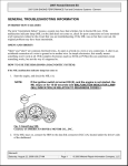
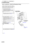
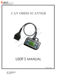
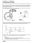
Main Menu
Table of Contents
Troubleshooting Procedures
Checking the Diagnostic Trouble Code (DTC)
with an OBD II Scan Tool or the Honda PGM Tester
When the PCM senses an abnormality in the input or output systems, the
light in the gauge assembly will
blink. When the 16P Data Link Connector (DLC) (located on the right side of the front console) is connected to the OBD II
Scan Tool or Honda PGM Tester as shown, the scan tool or tester will indicate the Diagnostic Trouble Code (DTC) when
the ignition switch is turned ON (II).
When the
light has been reported on, connect the OBD II Scan Tool conforming to SAE J1978 or Honda PGM
Tester to the DLC (16P). Turn the ignition switch on (II) and observe the DTC on the screen of the OBD II Scan Tool or
Honda PGM Tester. After determining the DTC, refer to the electrical system Symptom-to-Component Chart on pages
14-54 and 14-55.
NOTE: See the OBD II Scan Tool or Honda PGM Tester user's manual for specific instructions.
OBD II SCAN TOOL or
HONDA PGM TESTER
DATA LINK CONNECTOR (16P)
Table of Contents
Main Menu
Checking the Diagnostic Trouble Code (DTC)
with the Service Check Connector and Special Tool
When the PCM senses an abnormality in the input or output systems, the
light in the gauge assembly will
blink. When the Service Check Connector (located under the dash on the passenger side) is connected with the special
tool as shown, the
light will blink the Diagnostic Trouble Code (DTC) when the ignition switch is turned on
(II). When the
light has been reported on, connect the Service Check Connector with the special tool.
Then turn on (II) the ignition switch and observe the
light.
SERVICE CHECK
CONNECTOR (2P)
INDICATOR
LIGHT
GAUGE ASSEMBLY
SCS SERVICE CONNECTOR
07PAZ - 0010100
Codes 1 through 9 are indicated by individual short blinks. Codes 10 and above are indicated by a series of long and short
blinks. One long blink equals 10 short blinks. Add the long and short blinks together to determine the code. After determining the code, refer to the electrical system Symptom-to Component Chart on pages 14-54 and 14-55.
Short blink (once)
OFF
See DTC1
OFF
See DTC2
Long blink
OFF
Short blinks (five times)
See DTC15
Table of Contents
Main Menu
Troubleshooting Procedures
(cont'd)
1.
Remove the left heater lower cover (see section 20).
2.
Pull the carpet back to expose the PCM cover.
3. Remove the PCM cover mounting nuts, and turn the PCM over.
PCM
PCM
COVER
4.
Inspect the circuit on the TCM according to the troubleshooting flowchart with the special tools and a digital multimeter as shown.
How to use the Backprobe Set
Connect the backprobe adapters to the stacking patch cords, and connect the cords to a multimeter. Using the wire
insulation as a guide for the contoured tip of the backprobe adapter, gently slide the tip into the connector from the
wire side until it comes in contact with the terminal end of the wire.
Backprobe Adapter
DIGITAL MULTIMETER
(Commercially available)
KS-AHM-32-003,
or equivalent
BACKPROBE SET
07SAZ - 001000A (Two required)
Stacking Patch
Cord