1
Main Menu
Table of Contents
Troubleshooting
Troubleshooting Procedures
I.
How To Begin Troubleshooting
When the Malfunction Indicator Lamp (MIL) has been reported on, or there is a driveability problem, use the appropriate procedure below to diagnose and repair the problem.
A. When the MIL has come on:
1. Connect the Honda PGM Tester or an OBD II
scan tool to the 16P Data Link Connector (DLC)
located under the glove box behind a removable
cover.
2. Turn the ignition switch ON (II).
3. Check the DTC and note it. Also check and note
the freeze frame data. Refer to the Diagnostic
Trouble Code Chart and begin troubleshooting.
MALFUNCTION
INDICATOR
LAMP
(MIL)
NOTE:
See the OBD II scan tool or Honda PGM
Tester user's manuals for specific operating
instructions.
The scan tool or tester can read the Diagnostic Trouble Codes (DTC), freeze frame data, current data, and other
Engine Control Module (ECM) data.
Freeze frame data indicates the engine conditions when the first malfunction, misfire or fuel trim malfunction
was detected. It can be useful information when troubleshooting.
B. When the MIL has not come on, but there is a driveability problem, refer to the Symptom Chart on page 11-42.
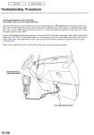
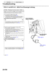
C. DTCs will be indicated by the blinking of the Malfunction Indicator Lamp (MIL) with the SCS service connector connected.
Connect the SCS service connector to Service Check Connector as shown. (The 2P Service Check Connector is
located under the dash on the passenger's side of the vehicle.) Turn the ignition switch on (II).
SERVICE CHECK
CONNECTOR (2P)
DATA LINK CONNECTOR (16P)
OBD II SCAN TOOL or
HONDA PGM TESTER
SCS SERVICE CONNECTOR
07PAZ-0010100
Main Menu
Table of Contents
Engine Control Module (ECM) Reset Procedure
Either of the following actions, will reset the ECM.
Using the OBD II scan tool or Honda PGM Tester to clear the ECM's memory.
NOTE: See the OBD II scan tool or Honda PGM Tester user's manuals for specific operating instructions.
Turn the ignition switch OFF. Remove the CLOCK (7.5 A) fuse from the under-hood fuse/relay box for 10 seconds.
CLOCK
(7.5 A) FUSE
UNDER-HOOD
FUSE/RELAY BOX
III.
Final Procedure (this procedure must be done after any troubleshooting)
1. Remove the SCS Service Connector if it is connected. If the SCS service connector is connected and there are no
DTCs stored in the ECM, the MIL will stay on when the ignition switch is turned on.
2. Do the ECM Reset Procedure.
3. Turn the ignition switch OFF.
4. Disconnect the OBD II scan tool or Honda PGM Tester from the Data Link Connector (16P).
IV.
Known-Good ECM Substitution
The ECM is part of the immobilizer system. If you substitute a known-good ECM, the ECM will have a different immobilizer code. In order for the engine to start, you must rewrite the immobilizer code with the Honda PGM Tester.
(cont'd)
Main Menu
Table of Contents
Troubleshooting
Troubleshooting Procedures (cont'd)
If the inspection for a particular code requires voltage or resistance checks at the ECM connectors, remove the bulkhead
panels. Unbolt the ECM. Check the system according to the procedure described for the appropriate code(s) listed on the
following pages.
ECM
BULKHEAD
PANELS
How to Use the Backprobe Sets
Connect the backprobe adapters to the stacking patch cords, and connect the cords to a multimeter. Using the wire insulation as a guide for the contoured tip of the backprobe adapter, gently slide the tip into the connector from the wire side
until it comes in contact with terminal end of the wire.
DIGITAL MULTIMETER
(Commercially available) or
KS - AHM - 32 - 003
STACKING PATCH
CORD
BACKPROBE SET
07SAZ - 001000A (two required)
BACKPROBE ADAPTER
Main Menu
Table of Contents
CAUTION:
Puncturing the insulation on a wire can cause poor or intermittent electrical connections.
Bring the tester probe into contact with the terminal from the connector side of wire harness connectors in the engine
compartment. For female connectors, just touch lightly with the tester probe and do not insert the probe.
TESTER PROBE
RUBBER SEAL
WIRE HARNESS
TERMINAL
Main Menu
Table of Contents
Troubleshooting
Troubleshooting Procedures (cont'd)
Symptom Chart
Listed below are symptoms and probable causes for problems that DO NOT cause the Malfunction Indicator Lamp (MIL) to
come on.
If the MIL was reported on, go to page 11-38.
Troubleshoot each probable cause in the order listed (from left to right) until the symptom is eliminated.
The probable cause and troubleshooting page reference can be found on next page.
SYMPTOM
PROBABLE CAUSE
Engine will not start
4,2,3,5,19,13,1
Hard starting
2,4,10,12,18
Cold fast idle too low
7,6
Cold fast idle too high
7,9,8
Idle speed fluctuates
7,9,8
Misfire or rough running
Troubleshoot for misfire on pages 11-90, 11-94
Low power
2,8,9, 11,16, 15,17,10
Engine stalls
2,4,10, 19,7,5, 14
Other Probable Causes:
Engine will not start
— Compression
— Engine locked up
— Timing belt
— Starting system
— Overheating
— Battery
Main Menu
Table of Contents
Probable Cause List (For the DTC chart, see page 11-52.)
Probable Cause
Page
1
11-61, 11-62
2
11-132, 11-139
3
11-143
4
Section 23
System
Engine Control Module (ECM)
Fuel pressure and fuel pump relay
PGM-FI main relay
Ignition system
5
See DTC chart
Crankshaft Position/Cylinder Position sensor circuit
6
See DTC chart
Intake Air Temperature (IAT) sensor circuit
7
11-128
Idle speed adjustment
8
11-151
Throttle body
9
11-150
Throttle cable
See DTC chart
Manifold Absolute Pressure (MAP) sensor
11
See DTC chart
Throttle Position (TP) sensor
12
See DTC chart
Barometric pressure (BARO) sensor
10
A/T gear position signal or clutch switch signal
13
11-122, 11-125
14
11-127
Brake switch signal
15
11-149
Air Cleaner
16
11-154
Intake Air Bypass (IAB) control system and intake air pipe
17
11-159
Three Way Catalytic Converter (TWC)
18
11-167
Evaporative emission (EVAP) control
19
Contaminated fuel
(cont'd)
Main Menu
Table of Contents
Troubleshooting
Troubleshooting Procedures (cont'd)
ECM Data
By connecting the OBD II scan tool or the Honda PGM Tester to the 16P data link connector (DLC), various data can be
retrieved from the ECM. The items listed in the table below conform to the SAE recommended practice.
The Honda PGM Tester also reads data beyond that recommended by SAE.
Understanding this data will help to find the causes of intermittent failures or engine problems.
NOTE:
The "operating values" given below are approximate values and may be different depending on the environment and
the individual vehicle.
Unless noted otherwise, "at idle speed" means idling with the engine completely warmed up, A/T in
or
position,
M/T in neutral, and the A/C and all accessories turned off.
Description
Operating Value
Diagnostic
Trouble Code
(DTC)
If the ECM detects a problem, it will store it as a code
consisting of one letter and four numbers.
Depending on the problem, an SAE-defined code
(POxxx) or a Honda-defined code (P1xxx) will be output
to the tester.
If no problem is detected,
there is no output.
Engine Speed
The ECM computes engine speed from the signals sent
from the Crankshaft Position sensor.
This data is used for determining the time and amount
of fuel injection.
Nearly the same as
tachometer indication at
idle speed:
A/T: 780 ± 50 rpm
M/T: 800 ± 50 rpm
YES
Vehicle Speed
The ECM converts pulse signals from the Vehicle
Speed Sensor (VSS) into speed data.
Nearly the same as
speedometer indication
YES
Manifold
Absolute
Pressure (MAP)
The absolute pressure created in the intake manifold by
engine load and speed.
With engine stopped:
Nearly the same as atmospheric pressure at idle
speed:
24-37kPa(180-280
mmHg, 7.1-11.0 inHg)
YES
Engine Coolant
Temperature
(ECT)
The ECT sensor converts coolant temperature into voltage and signals the ECM. The sensor is a thermistor
whose internal resistance changes with coolant temperature. The ECM uses the voltage signals from the
ECT sensor to determine the amount of injected fuel.
With cold engine:
Same as ambient temperature and IAT
With engine warmed up:
approx. 176-194°F
(80 - 90°C)
YES
Heated Oxygen
Sensor (HO2S)
(Bank 1, Sensor 1)
(Bank 1, Sensor 2)
(Bank 2, Sensor 1)
(Bank 2, Sensor 2)
The Heated Oxygen Sensor detects the oxygen content
in the exhaust gas and sends voltage signals to the
ECM. Based on these signals, the ECM controls the
air/fuel ratio. When the oxygen content is high (that is,
when the ratio is leaner than the stoichiometric ratio),
the voltage signal is lower. When the oxygen content is
low (that is, when the ratio is richer than the stoichiometric ratio), the voltage signal is higher.
0.0-1.25V
At idle speed:
about 0.1-0.9V
Data
Freeze Data
YES
NO
Main Menu
Data
Table of Contents
Description
Operating Value
Freeze Data
HO2S
Feedback
Loop Status
(Bank 1: Rear)
(Bank 2: Front)
Loop status is indicated as "open" or "closed".
Closed: Based on the H02S output, the ECM determines the air/fuel ratio and controls the amount of
injected fuel.
Open: Ignoring H02S output, the ECM refers to signals
from the TP, MAP, and ECT sensors to control the
amount of injected fuel.
At idle speed: closed
Short Term
Fuel Trim
(Bank 1: Rear)
(Bank 2: Front)
The air/fuel ratio correction coefficient for correcting
the amount of injected fuel when HO2S feedback is in
the closed loop status. When the signal from the HO2S
is weak, short term fuel trim gets higher, and the ECM
increases the amount of injected fuel. The air/fuel ratio
gradually gets richer, causing a higher H02S output.
Consequently, the short term fuel trim is lowered, and
the ECM reduces the amount of injected fuel. This
cycle keeps the air/fuel ratio close to the stoichiometric
ratio when in closed loop status.
-30%-+43%
Long Term
Fuel Trim
(Bank 1: Rear)
(Bank 2: Front)
Long term fuel trim in computed from short term fuel
trim and indicates changes occuring in the fuel supply
system over a long period.
If long term fuel trim is higher than 1.00, the amount of
injected fuel must be increased. If it is lower than 1.00,
the amount of injected fuel must be reduced.
-19%-+25%
Intake Air
Temperature
(IAT)
The IAT sensor converts intake air temperature into
voltage and signals the ECM. When intake air temperature is low, the internal resistance of the sensor
increases, and the voltage signal is higher.
With cold engine:
Same as ambient temperature and ECT
Throttle
Position
Based on the accelerator pedal position, the opening
angle of the throttle valve is indicated.
At idle: Approx. 10%
At full throttle: Approx.
90%
YES
Ignition
Timing
The ignition advance angle is set by the ECM. The ECM
matches ignition timing to the driving conditions.
At idle speed: 15 ±2°
BTDC with the SCS service
connector connected.
NO
Calculated
Load Value
(CLV)
CLV is the engine load calculated from the MAP data.
At idle speed:
YES
YES
YES
15-35%
At 2,500 rpm with no load:
12-30%
YES
YES