1
Computer Access Technology
Corporation
2403 Walsh Avenue, Santa Clara, CA 95051-1302 Tel: +1/408.727.6600 Fax: +1/408.727.6622
CATC™ UHT™
USB Hub Tester
User’s Manual
Version 2.1
11 October 1999
Copyright
1997–1999, Computer Access Technology Corporation (CATC)
CATC, Inspector, Detective, and UHT are trademarks of Computer Access Technology Corporation
CATC
UHT User’s Manual
Version 2.1
TABLE OF CONTENTS
1. INTRODUCTION................................................................................................................................................... 1
1.1 USB OVERVIEW ................................................................................................................................................. 2
2. CATC UHT SYSTEM ............................................................................................................................................ 2
3. SYSTEM SETUP .................................................................................................................................................... 4
3.1 CONNECTORS AND CABLES ................................................................................................................................. 5
4. SOFTWARE INSTALLATION ............................................................................................................................ 5
4.1 SOFTWARE COMPONENTS ................................................................................................................................... 5
4.2 INSTALLING THE SOFTWARE ................................................................................................................................ 5
4.3 RUNNING THE SOFTWARE ................................................................................................................................... 5
4.3.1 Setting the PIIX4 Interrupt Line Number ................................................................................................... 6
4.3.2 Command Line Options.............................................................................................................................. 6
5. UHT SOFTWARE FUNCTIONALITY................................................................................................................ 9
5.1 HUB TEST INITIALIZATION................................................................................................................................... 9
5.2 PORT TEST SEQUENCE ...................................................................................................................................... 10
5.3 OVERCURRENT PROTECTION TESTING .............................................................................................................. 11
5.4 TEST RESULTS................................................................................................................................................... 12
5.4.1 Test Results: Monitor Display .................................................................................................................. 12
5.4.2 Test Results: Disk Files ............................................................................................................................ 13
5.4.3 Test Results: Error Levels ........................................................................................................................ 14
5.5 CONFIGURATION FILE (FOR INTEL PIIX3 UHCI SYSTEMS ONLY)...................................................................... 16
6. HOW TO CONTACT CATC............................................................................................................................... 17
7. WARRANTY......................................................................................................................................................... 17
i
CATC
UHT User’s Manual
Version 2.1
1. INTRODUCTION
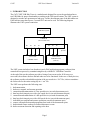
The CATC UHT USB Hub Tester is a modular unit designed for use on the production line to
test USB Hubs for proper functionality according to the USB specifications. The UHT system is
designed to test the one upstream port and up to 4 of the downstream ports of the hub under test.
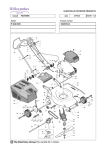
If the hub has more than 4 ports, a second UHT unit can be used. The following diagram
illustrates the UHT system connection:
USB Host System
USB HUB
(Device under test)
P0
P1
P2
P3
P4
P5
P6
Optional
CATC UHT
USB Hub Tester
(unit #2)
CATC UHT
USB Hub Tester
The UHT system includes a box (hardware) and a DOS application program (software) that
controls the test process by communicating directly with the PC USB Host Controller.
At the end of the test the software provides a listing of on-screen results. If all tests were
successful, the software declares the hub under test to be functional. In the case of faulty devices,
the software provides a detailed description of the test results in a “.fal” file; it also accumulates
the failure rate for the entire testing day in a “.sta” file.
The UHT tester performs the following tests:
1. hub enumeration
2. hub reset, suspend, and resume operation
3. connection and enumeration of a low-speed device (on each downstream port)
4. data loop-back integrity test with a low-speed device (on each downstream port)
5. connection and enumeration of a full-speed device (on each downstream port)
6. data loop-back integrity test with a full-speed device (on each downstream port)
7. individual port suspend and resume operations (on each downstream port)
8. remote wakeup detection and propagation from each of the downstream ports
9. hub-initiated remote wakeup on connect/disconnect events
10. hub overcurrent detection and reporting to the host
Page 1
CATC
UHT User’s Manual
Version 2.1
11. overcurrent protection (gang or per-port configuration)
12. downstream current restoration (overcurrent removed)
A complete test of a hub with four downstream ports takes about 10 seconds.
For hubs that fail these tests, a CATC Inspector™ or Detective™ USB Bus & Protocol Analyzer
can be used to assist in debug and rework.
1.1 USB Overview
USB is an open industry standard, providing a simple and inexpensive way to connect up to 127
devices to a single computer port. Keyboards, mice, tablets, digitizers, scanners, bar-code
readers, modems, printers, and more can all run at the same time. USB devices plug into any
platform that supports the standard, from notebooks to desktop PCs to workstations.
USB is a dynamically reconfigurable serial bus with an elementary data rate of 12,000,000
bits/sec, based on off the shelf, low cost micro-controller technology. Its modular layered
software protocol supports sophisticated device drivers and application programs.
Please refer to the USB Specifications for details on the USB protocol. The USB specifications
are available from the USB Implementers Forum at:
USB IF
M/S JF2-51
2111 NE 25th Avenue
Hillsboro, OR 97124
Tel: +1/ 503 264 0590
Fax: +1/ 503 693 7975
Web: http://www.usb.org/
2. CATC UHT SYSTEM
The CATC UHT package includes the following components:
•
•
a sturdy metal box housing the UHT electronic test circuitry, based on the Intel 8x930 USB
controller
an AC to DC power converter
•
four USB cables
•
a diskette with the CATC UHT DOS software program
•
this user’s manual
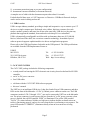
The UHT box is an intelligent USB device. It has four female B-type USB connectors and three
LEDs on the front of the unit and a +9V DC @ 500mA power connector on the rear. The USB
connectors (marked “CH 4” through “CH 1”) are used to connect the UHT box to the hub under
test. The power connector is used to power the box from the AC to DC power converter; when
power is applied, the red LED (marked “PWR”) is illuminated. The yellow LED (marked
“DATA”) is a status indicator; it blinks at a high rate to indicate that the on-board microcontroller is functioning properly, and at a low rate when the box is performing a test sequence. The
green LED (marked “CURRENT”) illuminates briefly when an overcurrent test is being
performed.
Page 2
CATC
UHT User’s Manual
Version 2.1
Front Panel
PWR
DATA CURRENT
CH 4
CH 3
CH 2
CH 1
Rear Panel
9V DC
The DOS-based UHT software runs on the USB host; it communicates with the UHT box via the
USB host controller (on the motherboard) and the USB hub under test. For each USB port, the
software program checks for proper operation in both full- and low-speed modes. When all tests
are successful, the software declares the USB hub to be functional; any failures are reported on
the computer display screen, and saved on the hard disk as a text file.
Page 3
CATC
UHT User’s Manual
Version 2.1
3. SYSTEM SETUP
Position the CATC UHT box on the test bench, near the USB hub to be evaluated. If a hub with
more than four ports is to be tested, position a second UHT test box nearby.
Connect the DC plug(s) of the AC to 9V DC @ 500mA power converter(s) to the +9V power
receptacle(s) of the CATC UHT box(es). To activate the unit, plug the AC to DC converter(s)
into appropriate AC power outlet(s).
In the USB test system, connect the CATC UHT box(es) as follows:
A) Connect a USB cable between the upstream port of the USB hub under test and the
USB port of the host PC.
B) Connect a USB cable between the first downstream port (of the USB Hub) to be
tested and the USB connector labeled “CH 1” on the (first) CATC UHT box.
C) Repeat step B for the next (and any additional) ports to be tested, connecting to
“CH 2”, “CH 3”, and “CH 4” in sequence. For hubs with more than four ports,
continue connecting them to “CH 1” through “CH 4” of the second UHT box, as
required.
If less than four downstream ports are being tested, the unconnected test channels on the UHT
box should be the higher numbered ones (e.g., if only two hub ports are being tested, they should
be connected to “CH 1” and “CH 2”). Similarly, if more than four ports are being tested, all
channels of the first UHT box must be filled, and unconnected channels on the second box
should be the higher numbered ones.
With one exception, downstream ports on the hub under test can be connected to the UHT box in
any order; this will only affect the sequence in which the ports are tested (the software will first
test the port connected to “CH 1”, then that connected to “CH 2”, and so on for any remaining
ports, continuing to the second box when appropriate). The exception is when a hub with 5, 6, or
7 ports is being tested: in this case it is important for the UHT software to know which is the
“second” UHT box (so it can tell the difference between unused connections and hub ports that
are not working). This is accomplished by requiring that the hub port connected to “CH 1” of the
first box be numbered lower than the hub port connected to “CH 1” of the second box.
The CATC UHT Hub Tester hardware is now ready for operation.
Note: To observe bus traffic, a CATC Inspector or Detective USB Bus & Protocol Analyzer can
be connected between the CATC UHT box and the hub under test, or between the hub and
the USB Host PC.
Page 4
CATC
UHT User’s Manual
Version 2.1
3.1 Connectors and Cables
All connectors have a limited life (i.e., number of connect/disconnects before failure). When
testing multiple hubs, be sure to plug and unplug cables at the hub only, not at the UHT box
(or the USB host). There is generally no need to disconnect the B-type USB connectors from the
UHT box (or the A-type connector from the host PC). There is also no need to power down the
UHT box between tests.
Additionally, forceful or otherwise improper connection and disconnection of USB cables can
damage the cables and connectors on the CATC UHT box, the USB host PC, and the hub under
test.
Note that the CATC Warranty (see “Warranty and License”) specifically excludes damage
caused by this kind of product misuse.
4. SOFTWARE INSTALLATION
4.1 Software Components
The CATC UHT software consists of the following files, included on the supplied diskette:
• USB_UHT.EXE
executable code of the CATC UHT program
• USB_UHT.CFG
configuration text file for the USB host controller
(used only for Intel PIIX3 UHCI systems)
4.2 Installing the Software
Make a copy of the CATC diskette for backup, then copy its contents to the hard drive of the
USB-capable PC to be used as the test system host.
4.3 Running the Software
The UHT software program (usb_uht.exe) is a DOS application, and must be run under the DOS
operating system. It supports both UHCI and OHCI USB host controller implementations; the
latter, however, requires use of the “/O” command line option (see the table below for further
details).
The program scans the PC’s PCI devices and locates the USB host controller by class code. It
uses the first host controller it finds as the test target. On some systems with a USB-aware BIOS,
the software may fail to communicate with the USB host controller; should this occur, contact
CATC technical support (see “How to Contact CATC”).
To run the program, type USB_UHT at the DOS prompt and press the “Enter” key. The program
will clear the monitor screen and begin execution. During the test, the program displays the test
results on the monitor screen. The tests conclude in less than 10 seconds, leaving the test results
on the screen. To terminate the program and get back to the DOS prompt, press any key.
Page 5
CATC
UHT User’s Manual
Version 2.1
4.3.1 Setting the PIIX4 Interrupt Line Number
In some computers the BIOS does not set the PIIX4 interrupt line, and as a result, the USB host
controller interrupt line remains disabled.
The UHT software allows setting of the PIIX4 interrupt line number, using the /I:N option, where
N is the IRQ number of the USB host controller (in the range 3–F).
If the IRQ setting is done by the BIOS, the /I option is not required.
When thus directed, the UHT software reads the Interrupt Line Register contents (function 2). If
a valid interrupt line number (3–F) is found, it uses this interrupt number even if the /I option
specifies a different IRQ number. If an invalid interrupt value is found (not 3–F) the driver alerts
the user with a screen message, stating that an invalid interrupt number was found, and requests
the use of the /I option to specify a valid IRQ value.
Ignoring the /I option when a valid IRQ number is detected allows the user to use the same
software configuration to run the UHT tester on different systems (where some need this option
and some do not).
When the /I option is used, the driver writes the specified IRQ number to both the Interrupt Line
Register and the PIRQD Route Control Register (function 0), and clears the Interrupt Routing
Enable bit of the latter.
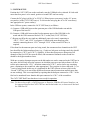
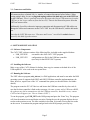
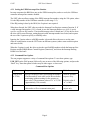
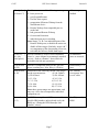
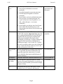
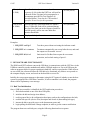
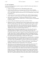
4.3.2 Command Line Options
The test program supports a variety of command line options. To use these options, type
USB_UHT (at the DOS prompt) followed by one or more of the following options, and press the
“Enter” key. Note that option switches may be either upper- or lowercase.
Command Line Options
Options
Purpose
Default
/A:n (n from
0–32768)
Specifies an integer value representing the number
of milliseconds to wait at the end of the test before
terminating (without waiting for the operator to
press a key). The maximum value of “n” is 32,768
(approximately 32.8 seconds).
Wait for operator
to press a key.
Sends all screen output to the console (so it can be
redirected to a file or communication port).
Display screen
output only.
/C
Page 6
Default value of
“n” is 1000.
CATC
UHT User’s Manual
Version 2.1
/D:n1[,n2,…]
(n from 0–7)
Disables one or more of the following test stages:
0 – basic power test
1 – port Suspend/Resume
2 – Get Bus State request
3 – propagation of Remote Wakeup from the
downstream device
4 – Remote Wakeup from suspended port on
awake hub
5 – hub-generated Remote Wakeup
6 – Overcurrent Protection
7 – individual port power switching
Note: Stages 3, 4, & 5 are individual parts of the
Remote Wakeup test; to disable the entire test,
disable all three stages. Similarly, stages 0 & 7
are components of the downstream power test;
to disable the full test, disable both stages.
All test stages are
enabled.
/E:n1[,n2,…]
(n = any
valid port #)
Specifies number(s) of one or more embedded
ports (i.e., ports assigned to permanently attached
devices—such as a monitor—that will not be
included in the hub test operations)
No embedded
ports are assumed.
/G:n (n from
0-120)
Provides a configurable delay for the “per port”
power switching test. Max. delay is 120 msec
Default delay is 72
msec.
/H:n (n from
0–10)
Selects one of the following current value ranges
for the overcurrent test:
0) 100–200mA
1) 250–450mA
2) 650–850mA
3) 1.3–1.5A
4) 2.0–2.2A
5) 2.3–2.5A
6) 3.0–3.2A
7) 3.8–4.0A
8) 4.4–4.6A
9) 4.6–4.8A
10) 4.7–5.0A
Note: these current ranges are approximate, and
may vary ±10% due to temperature, individual
components, etc.
See “Default
Overcurrent Test
Levels” table.
/I:n (n from
3–F)
Set PIIX4 interrupt line in USB host controller to
specified IRQ number, unless already set by the
BIOS (see “Setting the PIIX4 Interrupt Line
Number”, above).
Use IRQ as set by
BIOS.
Page 7
CATC
/M: n (n from
1–4)
UHT User’s Manual
Specifies a particular mode of overcurrent testing:
1 – test per-port (individual) overcurrent
protection
2 – test global (ganged) overcurrent protection
3 – test both per-port & global overcurrent
protection
4 – special mode, used only with hubs that implement per-port overcurrent protection, but
report overcurrent events as global (i.e., as
hub—rather than port—overcurrent
conditions)
Version 2.1
Use mode as
specified by hub
descriptor.
6 – special mode, provides per port OverCurrent
test for hubs that shut down power to all
downstream ports when an OverCurrent event
is detected
/O
Enables operation of the UHT software with an
OHCI USB controller. Important Note: there has
been widespread distribution of early OHCI host
controllers that do not properly implement the
USB protocol standard with respect to hub
functionality. In particular, it is quite common for
suspend/resume operations to malfunction. If
disabling test stages 3 and 5 (with /D:3,5) allows
the test to run with no other errors, this is likely the
cause. Contact the silicon vendor (or CATC) for
further information on this issue.
Test as UHCI USB
controller.
/P: n (n from
1–8)
Specifies the number of USB ports to be tested. If
/P:1 is specified, the software omits those test
stages that require the connection of a second
device (Get Bus State request and both types of
Remote Wakeup).
/P:4 (four ports)
/S:ON|OFF
Turns the “end of test” indicator sound on or off.
/S:ON (sound on)
/T:n (n from
0–20000)
Specifies the time (in milliseconds) for which
current will be applied during the overcurrent test.
This time will be rounded up to the nearest integer
multiple of 40ms.
/T:40 (40ms)
/V
Interrogates the UHT box and reports version
numbers of the UHT software and firmware.
N/A
Page 8
CATC
UHT User’s Manual
Version 2.1
/W:n (n from
1–2000)
Specifies the time (in microseconds, with an
accuracy of ±10µs) that the UHT box will wait for
a Remote Wake-Up signal to be propagated to a
downstream port (in Port Test Sequence #6,
described below). Note that the USB standard
specifies 50µs or less for this operation.
/W:100 (100µs)
/X:n (n from
0–10000)
Specifies the time (in milliseconds) for which a
heavy USB traffic load will be generated during
the test of the final port in the sequence (both lowand full-speed); used to test some hubs that
monitor bandwidth.
/X:0 (no traffic)
?
Displays this help information.
N/A
Examples:
1. USB_UHT /s:off /p:3
Test three ports without activating the indicator sound.
2. USB_UHT /a /c > test.res
Terminate automatically one second after the test, and send
the output to a file named “test.res”.
3. USB_UHT /d:2,6 /e:1
Omit tests for Get Bus State request & overcurrent
protection, and exclude testing of port #1.
5. UHT SOFTWARE FUNCTIONALITY
The DOS-based UHT software runs on the USB host; it communicates with the UHT box via the
USB host controller (on the motherboard) and the USB hub under test. For each USB port, the
software program checks for proper operation in both full- and low-speed modes. When all tests
are successful, the software declares the USB hub to be functional; any failures are reported on
the computer display screen, and saved on the hard disk as a text file.
Initially, the test program attempts to determine (using the PCI protocol) whether or not the host
system is equipped with a USB Host Controller; if such a controller is not found, the program
aborts with an explanatory error message.
5.1 Hub Test Initialization
Once a USB host controller is identified, the UHT application proceeds to:
1. find a hub attached to one of the host USB ports;
2. initialize the hub and assign it an address;
3. read its general device & configuration descriptors, and set the configuration to the hub;
4. read the hub-specific (device class) descriptor and decode it (determining hub type);
5. instruct the hub to provide power to the downstream ports; and
6. begin polling the hub Status Change endpoint, in order to get the connect notification.
The program then tests each hub port, using the following functional test sequence.
Page 9
CATC
UHT User’s Manual
Version 2.1
5.2 Port Test Sequence
Each of the following functions is tested, in sequence (in both full- and low-speed modes), for
each downstream hub port:
1. Connect event (processed as done by a USB-enabled operating system)
2. initialization of the USB device (incorporated in the UHT box) and data loopback
sequence [During data loopback, a set of 75 random data bytes is sent to the UHT box on
its OUT bulk endpoint, and then read back on one of its IN bulk endpoints; this procedure
is repeated twice.]
3. verification that power is provided to the USB port, and—for hubs with per-port power
control—that power can be turned on and off [using SetPortFeature(PORT_POWER)]
4. individual port suspend/resume [The hub port to which the UHT box is currently
connected is suspended for 50ms, and the UHT box verifies the presence of both Suspend
and Resume events.]
5. optional Get Bus State diagnostic request (state is returned or STALL)
6. propagation of the device-generated Remote Wakeup signaling upstream and to enabled
USB ports during suspend [The hub under test is suspended, while two ports on it have
devices connected and enabled. Then, after approximately 50ms, the UHT box sends a
Remote Wakeup signal on one of those ports. The hub is supposed to propagate this
signal upstream to the host, and downstream to the other enabled port. This behavior is
verified by host software in cooperation with the UHT box.]
7. handling of Remote Wakeup from a suspended port on an awake hub [The software
suspends the hub port to which the UHT box is currently connected. Then, after
approximately 50ms, the UHT box sends a Remote Wakeup signal on this port. The hub
is supposed to complete the Resume signaling on this port and notify the host about the
change, which it does by sending the Hub Bitmap (with the corresponding port bit set)
from the Status Change interrupt endpoint, and also by setting the C_PORT_SUSPEND
bit in the Hub Status. This functionality is verified by the UHT system.]
8. generation of the upstream Remote Wakeup signal upon connect/disconnect event during
suspend [The hub under test is suspended, while two ports on it have devices connected
and enabled. Then, after approximately 50–100ms, the UHT box creates a disconnect
event on one of these ports. The hub is supposed to respond to this by sending a Remote
Wakeup signal to the host. The software verifies this functionality. After the Resume
signaling is completed by the host, the disconnect event is processed.]
9. optional port overcurrent reporting [This function is executed for each port only if the
software determines (from the Hub Descriptor) that the hub implements per-port
(individual) overcurrent protection. For this test the software instructs the UHT box to
create an overcurrent condition on the port under test, and expects the hub to shut down
the power to this port and report the condition, which the hub does by sending the Hub
Bitmap (with the corresponding port bit set) from the Status Change interrupt endpoint,
and also by setting the C_PORT_OVER_CURRENT bit in the Hub Status. Then, after
about 50ms, the software instructs the hub to restore power to the port, and processes the
UHT device connection on this port in order to proceed with the test. If the hub supports
Page 10
CATC
UHT User’s Manual
Version 2.1
global (ganged) overcurrent protection, the testing is done in a similar fashion, but at the
end of the test (i.e., after completing the set of individual port tests).]
10. Disconnect event [The UHT box is instructed to disconnect itself from the current port
(Channel), and reconnect after some time at a different port and/or speed.]
During the test of each port, the system connects (between functions 4 and 5, above) and
disconnects (between functions 9 and 10) a full-speed device on some other hub port (the port
connected to the “next” channel on the UHT box). This is required for testing the Get Bus State
request (function 5) and both aspects of Remote Wakeup (functions 6 and 8). If only one
downstream port is being tested, these tests are necessarily omitted.
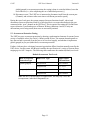
5.3 Overcurrent Protection Testing
The UHT box tests overcurrent protection by drawing a predetermined amount of current (from a
variety of available values) for a brief (<100ms) period of time. The amount drawn depends on
how the test hub is powered (from the bus or its own local supply), and whether it implements
global (ganged) or per-port (individual) overcurrent protection.
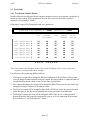
Further, a hub may have a designed current trip point that differs from that normally tested by the
UHT device; for this reason, the /H switch enables the specification of a variety of current draws,
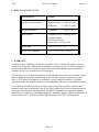
ranging up to a full 5 Amperes. The following table enumerates the standard (default) test levels:
Default Overcurrent Test Levels
Hub Overcurrent
Protection Type
Hub Power Type
Approximate
Current Draw
global (ganged)
bus-powered
650–850mA
self-powered
2.3–2.5A
bus-powered
250–450mA
self-powered
650–850mA
per-port (individual)
Note: the above current ranges are approximate, and may vary ±10% due
to temperature, individual components, etc.
Page 11
CATC
UHT User’s Manual
Version 2.1
5.4 Test Results
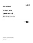
5.4.1 Test Results: Monitor Display
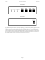
Results of the tests are displayed on the computer monitor screen (a color monitor is preferred, as
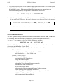
results are color-coded). If all test functions succeed, the overall test is declared “passed”;
otherwise, it is reported as “failed”.
Following is a typical UHT displayed result for a passed test:
Found Hub with VENDOR_ID = XXXX, PRODUCT_ID = XXXX
Data
Full
Low
Full
Low
Full
Low
Full
Low
Speed
Speed
Speed
Speed
Speed
Speed
Speed
Speed
Port
Port
Port
Port
Port
Port
Port
Port
1
1
2
2
3
3
4
4
Connect/ Power
Disconnect
OK
OK
OK
OK
OK
OK
OK
OK
OK
OK
OK
OK
OK
OK
OK
OK
T E S T
OK
OK
OK
OK
OK
OK
OK
OK
Remote
Wakeup
OverCurrent
OK
OK
OK
OK
OK
OK
OK
OK
OK
OK
OK
OK
OK
OK
OK
OK
P A S S E D
Note: Port numbers are displayed in the order tested, which may not be in strict numerical
sequence as shown in the above example.
For failed tests, the results may differ as follows:
•
•
•
•
The Data test result will be changed to BAD if initialization of the UHT box failed, or data
received during the data loopback test doesn’t match the expected data, or suspend/resume of
an individual port doesn’t work, or the Get Bus State request failed.
The Connect/Disconnect test result will be changed to BAD if there was an error or time-out
during processing of Connect or Disconnect events.
The Power test result will be changed to BAD if the UHT doesn’t sense the power provided
on the hub port, or fails the power switching test on per-port power controlled hubs.
The Remote Wakeup test result will be changed to BAD if the device- or hub-generated
Remote Wakeup wasn’t properly propagated or sent, or to N/A if connection of the second
device failed (see “Port Test Sequence”, above).
Page 12
CATC
•
UHT User’s Manual
Version 2.1
The Overcurrent test result will be changed to BAD if the hub reported an overcurrent event
and then failed in subsequent processing, or to *** if the overcurrent event was created, but
the hub didn’t report it. In the latter case the following message (as appropriate to the
overcurrent test in question) will appear at the bottom of the test screen:
*** – Didn’t trip on … (test current value)
Note: If, at the beginning of a test, the UHT software senses that the UHT box is not connected
to any of the hub’s USB ports, the program declares a test failure, displaying the message:
Found Hub with VENDOR_ID = XXXX, PRODUCT_ID = XXXX
The Hub Tester Device is not connected to the hub!
T E S T
F A I L E D
5.4.2 Test Results: Disk Files
The UHT application always generates two text files: one with the extension “.sta” , another with
the extension “.fal”. The root name of both files is constructed from the current date, as
“yy_mm_dd”. For example, on July 3rd, 1998 the file names would be:
98_07_03.sta
and
98_07_03.fal
In the “.sta” file, the program records production statistics for the current day: the number of
units passed and the number of units failed.
In the “.fal” file is recorded a failure description for each failed unit, as follows:
Failure #n, Unit #m
Before failure, passed for ports: n1, n2, … (or NONE)
Failed for Port #n at … speed. Failed items:
followed by one or more of:
Bad connect handling.
Error initializing Hub Tester device.
Wrong data on data loopback.
Power is not provided to the port.
Bad handling of port Suspend/Resume commands.
Bad connection of the second device.
Get Bus State request failed.
Bad propagation of device-generated Remote Wakeup upstream.
Remote Wakeup wasn’t propagated downstream.
Bad handling of Remote Wakeup from suspended port on awake hub.
Hub didn’t send Remote Wakeup on disconnect event.
Bad disconnection of the second device.
Page 13
CATC
UHT User’s Manual
Version 2.1
Bad individual overcurrent protection.
Bad disconnect handling.
5.4.3 Test Results: Error Levels
Upon termination, the UHT application sets the DOS error level according to the test results. If
the test passed, it exits with error level 0; otherwise it exits with a corresponding error level. This
feature allows processing of the test results in a batch file, or when the program is spawned as a
child process by another application.
The error level (result_code) is calculated as the sum of two components:
result_code = passed_ports_code + failed_port_code
The passed_ports_code portion allows determination of which ports completely passed the
test before the failure occurred; the failed_port_code portion allows determination of which
port failed, at what speed, and at which test stage.
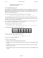
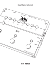
Five test stages are specified (per the test results screen): Data (DT), Connect/Disconnect (CD),
Power (PW), Remote Wakeup (RW), and Overcurrent (OC).
The failed_port_code is computed as follows:
failed_port_code = (failed_port_number-1) * 10 + failure_code
where failure_code is chosen according to this table:
DT
CD
PW
RW
OC
Full Speed
0
1
2
3
4
Low Speed
5
6
7
8
9
The passed_ports_code is computed as the sum of
( 2^(passed_port_number-1) ) * 100
for all ports successfully passing the test..
There are also four special cases:
•
Initialization of the hub failed (result_code = 30000);
•
The software doesn’t detect a hub connected to the host when the test begins (result_code
= 30001);
•
The software doesn’t detect a UHT box connected to the hub under test when the test begins
(result_code = 30002);
•
The individual ports passed, but the Global Overcurrent protection test failed (result_code
= 30003).
Page 14
CATC
UHT User’s Manual
Version 2.1
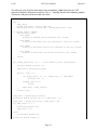
The following code fragment demonstrates how the result_code returned by the UHT
application might be interpreted in software. This “C” language function takes result_code as
a parameter, and prints out the decoded test results:
void Decode_UHT_test_results ( int result_code )
{
int i,
temp_value,
passed_ports_base = result_code/100,
failed_port_value = result_code - passed_ports_base * 100;
if (result_code >= 30000){
switch(result_code){
case 30000:
printf("\n Problem initializing hub.\n"); break;
case 30001:
printf("\n Hub under test not connected to host.\n"); break;
case 30002:
printf("\n Hub Tester Device not connected to hub.\n"); break;
case 30003:
printf("\n Bad global overcurrent protection.\n"); break;
}
return;
}
if( passed_ports_base != 0 ) // zero means no ports fully passed
{
printf(" Passed at ports: ");
temp_value = passed_ports_base;
for(i=1; i<=8; i++)
{
if( (temp_value / 2) * 2 < temp_value ) // odd number
printf(" %d", i);
if(temp_value == 1)
break;
temp_value = temp_value/2;
}
printf(".\n");
}
temp_value = failed_port_value/10;
printf("\n Failed on port %d at ", temp_value + 1);
temp_value = failed_port_value - temp_value * 10;
if( temp_value > 4 ) {
printf("low speed.\n");
temp_value -= 5;
}else
printf("full speed.\n");
printf("\n Failed stage: ");
Page 15
CATC
switch(temp_value){
case 0: printf("
case 1: printf("
case 2: printf("
case 3: printf("
case 4: printf("
}
UHT User’s Manual
Version 2.1
Data\n"); break;
Connect/Disconnect\n"); break;
Power\n"); break;
Remote Wakeup\n"); break;
Overcurrent Protection\n"); break;
}
5.5 Configuration File (for Intel PIIX3 UHCI systems only)
If the system under test has a BIOS that disables the USB portion of the Intel PIIX3 Host
Controller, the UHT software will enable it for the duration of the test, and then restore the
previous settings.
In order to run the test, the software needs certain information about the controller configuration:
the I/O base address for PIIX3 function 2 (USB portion), the IRQ assigned to the host controller,
and the USB Clock Selector (if host controller runs at 24 or 48 MHz).
In order to provide this input, a configuration text file (usb_uht.cfg) is included with the UHT
software, containing two lines, as in the following example:
; I/O Space IRQ Clock
0xF300
11
48
This file should be used to provide input for the above cases. If the “.cfg” file is not present, the
program will use the default values as shown above (0xF300 11 48). For the clock input, only
two values are accepted: 24 and 48; any other values are ignored, and 48 used as a default. The
I/O base address should be entered in hexadecimal, IRQ as an integer.
The values in usb_uht.cfg are used by the program only when the USB (Function 2 in PIIX3) is
disabled by the BIOS.
Page 16
CATC
UHT User’s Manual
Version 2.1
6. HOW TO CONTACT CATC
7.
Type of Service
Contact
Call for technical support...
US and Canada: +1/ 800 909 2282
Worldwide:
+1/ 408 727 6600
Fax your questions...
Worldwide:
+1/ 408 727 6622
Write a letter...
Computer Access Technology Corp.
Customer Support
2403 Walsh Avenue
Santa Clara, CA 95051-1302
Send e-mail...
[email protected]
Visit CATC’s Website...
http://www.catc.com/
WARRANTY
Computer Access Technology Corporation (hereafter CATC) warrants this product to be free
from defects in material, content, and workmanship, and agrees to repair or replace any part of
the enclosed unit that proves defective under these terms and conditions. Parts and labor are
warranted for one year from the date of first purchase.
This warranty covers all defects in material or workmanship. It does not cover accidents, misuse,
neglect, unauthorized product modification, or acts of nature. Except as expressly provided
above, CATC makes no warranties or conditions, express, implied, or statutory, including
without limitation, the implied warranties of merchantability and fitness for a particular purpose.
CATC shall not be liable for damage to other property caused by any defects in this product,
damages based upon inconvenience, loss of use of the product, loss of time or data, commercial
loss, or any other damages, whether special, incidental, consequential, or otherwise, whether
under theory of contract, tort (including negligence), indemnity, product liability, or otherwise. In
no event shall CATC’s liability exceed the total amount paid to CATC for this product.
Page 17