1
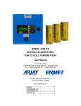
MODEL 4300-PG CENTRAL ACCESS PANEL FOR EC-GOLD TRANSMITTERS User Manual Technical Support Continental North America Toll Free 1-(800) 387-9487 Ph: +1 (905) 829-2418 Fx: +1 (905) 829-4701 A Product of Arjay Engineering Ltd. Oakville, Ontario, Canada www.ArjayEng.com MODEL: HARDWARE NO.: SOFTWARE NO.: SERIAL NO.: Model: 4300-PG User Manual TABLE OF CONTENTS 1.0 2.0 3.0 4.0 5.0 6.0 7.0 8.0 INSTRUMENT OVERVIEW ............................................................................................3 1.1 Features .............................................................................................................4 1.2 Specifications .....................................................................................................5 INSTALLATION...............................................................................................................6 2.1 Main Panel Installation .......................................................................................6 2.2 Sensor and RAB Installation ..............................................................................6 STARTUP AND CONFIGURATION ...............................................................................7 3.1 Status Indications ...............................................................................................7 3.2 Password Protection ..........................................................................................7 3.3 Display Screens .................................................................................................7 3.3.1 Zone Alarm Status Screen ..................................................................8 3.3.2 Real Time Screen ................................................................................9 3.3.3 Overall Alarm Status Screen ...............................................................9 3.3.4 Remote Relay / Analog Board (RAB) Status Screen ..........................9 3.3.5 Zone ppm Status Screen .....................................................................10 3.3.6 Individual EC Gold Transmitter Status ................................................10 3.3 Notes on the user interface ................................................................................11 SETUP CONFIGURATION .............................................................................................12 4.1 Zone / Sensor Setup ..........................................................................................12 4.2 Remote Sensor Status .......................................................................................12 4.3 4300-PG Setup ..................................................................................................13 4.4 mA Output Setup................................................................................................14 CONTROL CONFIGURATION .......................................................................................15 5.1 Set Gas Alarm Values / mA Span ......................................................................15 5.2 Alarm Delay........................................................................................................16 5.3 Tools ..................................................................................................................16 5.3.1 Fan Cycle ............................................................................................16 5.3.2 Force 20mA Output .............................................................................17 5.3.3 Force Zone Alarms ..............................................................................17 5.3.4 Fan Run Time ......................................................................................17 5.4 Relay Map Setup................................................................................................18 5.4.1 4300-PG Internal Relay Setup ............................................................18 5.4.2 Remote Relay / Analog Board (4300-RAB) Setup ..............................19 CALIBRATION SETUP ...................................................................................................20 6.1 Calibration ..........................................................................................................20 6.2 Calibration using EC Gold Pushbutton ..............................................................20 6.3 Calibration from the 4300-PG ............................................................................20 6.3.1 Auto Calibration ...................................................................................21 6.3.2 Manual Calibration Methods................................................................21 6.4 Change Remote EC Gold Transmitter Alarm Information .................................21 6.5 Change Remote EC Gold Transmitter mA Output.............................................21 6.6 Record Calibration Date .....................................................................................22 SETTING SHEET............................................................................................................23 7.1 Gas Alarm Setup ................................................................................................23 7.2 Zone Parameter Setup .......................................................................................25 7.3 Relay Mapping ...................................................................................................29 7.3.1 4300-PG Internal Relay Mapping ........................................................29 7.3.2 Remote Relay / Analog (RAB) Relay Mapping ...................................29 DETAILED ELECTRICAL AND DIMENSIONAL DRAWINGS ........................................35 TABLE OF FIGURES Figure 1 – User Interface .............................................................................................................. 7 2 Rev: 1.0 Model: 4300-PG 1.0 User Manual Rev: 1.0 INSTRUMENT OVERVIEW The Arjay Model 4300-PG is a flexible monitoring and control system for ventilation of Carbon Monoxide, Nitrogen Dioxide and Propane gas in apartment buildings, offices, commercial buildings, public parking facilities and maintenance garages. The 4300-PG unit is field configured for the number of zones (up to 16) and sensors per zone. The 4300-PG provides a central panel that continuously scans the field of sensors for gas concentrations. When a sensor indicates a high level of gas, the controller will determine its zone location and assign the appropriate fan to take action. Should the gas concentration continue to rise, additional fans can be called upon. The unique cross-mapping feature can call upon fans in different areas or garage levels or alert concierge, control room or security centers. In multi-level garages or garages with multiple fan locations, zone control and cross mapping optimizes energy efficiency by starting fans only in areas where ventilation is needed. When adequate ventilation is achieved, the fans automatically resume their normal or off speed. Using the above setup information, the 4300-PG unit continuously scans all the EC Gold transmitters for their gas type and measured concentration. Up to 4 gas types are supported. For example, the 4300-PG may be configured to monitor Carbon Monoxide, Carbon Dioxide, Nitrogen Dioxide, and Methane. The Low, High, High-High1 and High-High2 alarm values are independently entered for each gas. A zone Low alarm is triggered if the concentration of any of the target gases in that zone exceeds the Low alarm value for that gas. There are a total of 64 possible alarms: Low, High, High-High1 and High-High2 alarms per zone for up to 16 zones. Main Panel and Remote Auxiliary Relay Board (RAB) The 4300-PG supports four (4) internal relays plus up to 8 Remote Auxiliary relay Boards (RAB) with up to 8 relays each for a total of 64 relays. The 4300-PG communicates with the RAB via RS-485 Modbus. Therefore the RAB may be located conveniently anywhere on the sensor runs. Each of the 64 relays may be independently mapped in the field to any of the 64 alarms (Low, High, High-High1 and High-High2 for up to 16 zones). For Example, Relay1 may be mapped to Zone 1 Low Alarm as well as the High Alarm for all other zones. Relay2 may be mapped to Zone 2 Low Alarm as well as the High Alarm all other zones. This scheme will turn on the individual relays 1 and 2 when their respective zones go into Low alarm, and both relays will turn on when any zone goes into High or High-High alarm. This flexibility ensures efficient use of the relays, which can be tailored to unique system requirements. The common Trouble alarm is set if any EC Gold transmitter has a fault, or does not respond on the network. The Internal Relay1 can be designated as System Fault Alarm (or the common Trouble alarm) relay. Independent Delay to On and Delay to Off can be set for each zone alarm. For each zone, the maximum ppm values are calculated and transmitted on 2 standard 4-20mA outputs. 3 Model: 4300-PG 1.1 User Manual Rev: 1.0 Features Automatic scanning of up to 96 EC Gold network sensors. Up to Six (6) wire runs from 4300-PG allowing more flexibility when wiring the EC Gold sensors. Sensors may be assigned to any of 16 zones 2 Standard 4-20mA outputs per zone to reflect the zone’s max. ppm Differential (dual threshold), independent, High-High2, High-high1, High, and Low alarms per zone. Alarm thresholds may be independently set for up to 4 gases. Four (4) internal SPDT 3A relays plus up to 8 Remote Auxiliary relay Boards (RAB) with up to 8 relays each. Each relay is user selectable to be linked to any combination of 24 alarm sources: High-High, High and Low alarms for all 8 zones. Internal Relay1 can be designated for System Fault Alarm. Optional Buzzer output linked to common High-High 2 alarm. Each Auxiliary relay board also has a buzzer output and push to acknowledge input. Independent Delay to On and Off for all zones, plus a 60 minute override function in order to test system without time delay. Push to test function for all zones alarms and 4-20mA outputs. Delay to ON for buzzer alarm. Calibration reminder setting. RS-485 Modbus protocol to communicate with the EC Gold sensors. RS-485 Modbus protocol for upstream BAS. Front panel LCD and membrane keypad user interface. Optional data logging for events. Fan cycling on low alarm relays available in order to turn fans On in peak periods. 4 Model: 4300-PG 1.2 User Manual Rev: 1.0 Specifications Power Input: 24VDC / current depends on number of transmitters (100mA per sensors) User Interface: Calibration & Setup Network - 4 Line x 20 Character LCD and 4x4 membrane keypad. - RS-485 Modbus protocol connection to EC Gold sensor. - RS-485 Modbus protocol connection to upstream BAS. - Differential threshold Low, High, High-High1 and High-High2 alarms per zone for up to 16 zones. - Up to 4 gases are supported with independent Low, High, High-High1 and High-High2 alarms for each gas type. - Common Sensor Fault alarm - 4 internal SPDT 3A relays and up to 64 external SPDT 10A/120VAC relays in banks of 8. - Each bank of 8 is accessible via RS-485 and may be located where convenient to save wiring. - Each relay may be field linked to any combination of 64 alarm sources: High-High2, High-High1, High and Low alarms per zone for up to 16 zones. - Internal Relay1 may be designated as a System Fault alarm. Alarm Delay - Independent Delay to On and Delay to Off for each zone alarm. Delay range: 0-99 minutes field adjustable Buzzer (Optional) - Activated by any zone’s High-High alarm with acknowledge input. Each bank of 8 relays also includes a buzzer and acknowledge input. 4-20mA Outputs - 2 internal mA outputs and 2 per Remote Auxiliary Relay Board (RAB) Outputs: Alarms Relay Contacts Environmental: Ambient Temperature 0 - 55°C Relative humidity 90% max. with no condensation Mechanical Specification: Refer to dimensional drawing 5 Model: 4300-PG 2.0 User Manual Rev: 1.0 INSTALLATION NOTE: If any damage to the instrument is found, please notify an Arjay Engineering representative as soon as possible prior to installation. 2.1 Main Panel Installation Choose a mounting location in accordance with good instrument practice. Extremes of ambient temperature and vibration should be avoided (see specifications and installation drawing). There are up to six (6) wire runs available for sensors. Sensors must be daisy chained along each wire (NO T-Tapping). Zones are in a sequential format (e.g. Zone 1: 1-10, Zone 2: 11-20 etc.) All user connections are via mating plug/receptacle connectors to make installation and service easier. IMPORTANT NOTE: RS485 communication wire must be shielded and must not be run in same conduit as high voltage lines. The shield of the cable must be daisy chained as well and grounded to earth ground at main panel. If splitter boxes are used in ceilings, make sure the shields are also connected together. 2.2 Sensor and RAB Installation The sensors and RAB can be mounted up to 4000 feet maximum away from the main panel. (Longer wire runs may require a RS485 repeater). Recommended Cables: 1. For 24VDC Power: 2 Conductor 14-16AWG Shielded Cable 2. For RS485 Network: 2 Conductor Low Capacitance 22-24AWG Shielded Cable (Belden 9841, 3105A or equivalent) CAUTION: THE UNIT HOUSES SENSITIVE ELECTRONIC COMPONENTS AND SHOULD BE HANDLED WITH CARE. IF PUNCHING OR DRILLING THROUGH THE ENCLOSURE WALLS, MAKE SURE THAT THE INTERNAL ELECTRONIC MODULES ARE SHIELDED FROM DEBRIS ESPECIALLY METAL PARTICLES. PLEASE MAKE SURE THAT THE CONNECTIONS HAVE THE POLARITY AS INDICATED OR THE CONTROLLER MAY BE DAMAGED. USE GOOD INSTALLATION PRACTICE! DO NOT RUN HIGH VOLTAGE CABLE IN THE SAME CONDUIT AS SIGNAL WIRES. 6 Model: 4300-PG 3.0 User Manual Rev: 1.0 STARTUP AND CONFIGURATION Figure 1 – User Interface 3.1 Status Indications One LED per Relay status. Each relay is triggered by the user-selected combination of zone HighHigh2, High-High1, High and Low alarms. 3.2 Password Protection A password must be entered to access any of the 3 value entry menus: CALIB, CONTROL, SETUP. The factory default password is 2000. The prompt for entering the password is always 9999 regardless of the actual password. 3.3 Display Screens After power up and the initial startup screen has been displayed for about 3 seconds, the CAP scans all active EC Gold transmitters on the network (as set by the "number of remotes" setting explained later). This may take several seconds depending on the number of sensors. The following screen will now appear: Z Z Z Z 1: 2: 3: 4: Ok Ok Ok Ok PLEASE NOTE: ALL DISPLAY SHOWN IN THIS MANUAL ARE FOR EXAMPLE ONLY. ACTUAL VALUES WILL BE VARY. 7 Model: 4300-PG User Manual Rev: 1.0 3.3.1 Zone Alarm Status Screen The following is a typical display: Z Z Z Z 1: 2: 3: 4: Ok Ok Ok Ok The alarm status is displayed for each zone . If there are more than 4 zones, then press the <DISPLAY> key to view the status of the remaining zones. Each line starts with the zone number and displays the zone status. The status may be one of the following: OK All EC Gold transmitters in this zone are responding on the network, are functioning properly and there are no gas alarms. Low Alarm At least one EC Gold transmitter in this zone has a ppm level at or above the Low Alarm ppm level for at least the Low Alarm Delay On time. High Alarm At least one EC Gold transmitter in this zone has a ppm level at or above the High Alarm ppm level for at least the High Alarm Delay On time. HiHi1 Alarm At least one EC Gold transmitter in this zone has a ppm level at or above the High-High1 Alarm ppm level for at least the High-High1 Alarm Delay On time. HiHi2 Alarm At least one EC Gold transmitter in this zone has a ppm level at or above the High-High2 Alarm ppm level for at least the High-High2 Alarm Delay On time Xmtr error At least one EC Gold transmitter in this zone has a sensor fault or instrument fault. No response (NR) At least one EC Gold transmitter in this zone is not responding on the network. DEL> Alarm delay ON DEL< Alarm Delay OFF Fan Cycle ON CAL Reminder Sensor calibration reminder 8 Model: 4300-PG User Manual Rev: 1.0 3.3.2 Real Time Screen To view this screen, press the <ENTER> key while viewing the Zone alarm status screen. Current Date / Time 2013/06/30 19:19:19 YYYY/MM/DD HH:MM:SS Press <ENTER> key to return to Zone alarm status screen. 3.3.3 Overall Alarm Status Screen To view this screen, press the <DISPLAY> key while viewing the Zone Alarm Status Screen. Max ppm=25 by #5 Network: OK Xmtrs: OK Alarm status: Low The top line displays the maximum ppm registered by any EC Gold transmitter in any zone and the transmitter network address which caused it. The second line displays the network status: either “OK” if all active EC Gold transmitters and networked resources are responding, or “Net no response: x” and the number (quantity) of not responding transmitters or networked resources is displayed. For example if 1 EC Gold transmitter and 1 RAB board are not responding then "Net no response: 2" is displayed. The third line displays the common EC Gold transmitter status. This includes EC Gold transmitters that have sensor faults or if they are not responding on the network. If all EC Gold transmitters are OK, then “OK is displayed, else “Xmtr trouble: x” is displayed where “x” is the number (quantity) of EC Gold transmitters with sensor or instrument faults or not responding. Note: if an EC Gold transmitter is not responding then this will be indicated on line 2 and 3 i.e. you will get “Net no response” and “Xmtr trouble” errors. 3.3.4 Remote Relay / Analog Board (RAB) Status Screen To view this screen, press the <DISPLAY> key while viewing the Overall Alarm Status Screen. RAB1: OK RAB2: OK The status of the Auxiliary Relay Boards (RAB) is displayed. If only one RAB module is installed, the bottom 3 lines are blank. “OK” means the RAB module is responding on the network. 9 Model: 4300-PG User Manual Rev: 1.0 3.3.5 Zone ppm Status Screen To view this screen, press the <DISPLAY> key while viewing the Zone ppm Status Screen. Z1Hi/Av: Z2Hi/Av: Z3Hi/Av: Z4Hi/Av: 25(05)/ 3 12(11)/ 5 0(20)/ 0 0(32)/ 0 The ppm status is displayed for each zone. If there are more than 4 zones, press the <DISPLAY> key to view the status of the remaining zones. Each line starts with the zone number. The first value is the highest ppm recorded for that zone together with the transmitter network address causing this value. The average value for the entire zone is displayed at the end of the line. In the example above, zone 1 has a high of 25ppm caused by EC Gold transmitter # 5. The average for the zone is 3 ppm. 3.3.6 Individual EC Gold Transmitter Status The status of individual EC Gold transmitters may be viewed by pressing the following keys on the keypad while in any of the screens described above in sections 3.3.1 – 3.3.5: Press the zone number to get to the corresponding zone sensor status. For example for zone 1 press “1”. The ENTER key does not need to be pressed. In order to see zones greater than 9 than you will need to view the Zone Alarm Status Screen for zone 9 – 11 and then PRESS 0 for 10 1 for 11 2 for 12 The status of individual EC Gold transmitters for the corresponding zone are displayed 11 at a time. If more than 11 transmitters are assigned to the zone, then press the DISP key repeatedly to view the status of remaining EC Gold transmitters, 11 at a time. For each EC Gold transmitter, the ppm value is beside each sensor number. The status is displayed followed by a 2 letter code: NR = no response from EC Gold ER = Instrument error Pressing the <DISPLAY> key when the last transmitter is on screen cycles back to the Main Display. 10 Model: 4300-PG 3.3 User Manual Rev: 1.0 Notes on the user interface When entering in numeric values, the cursor can be backspaced to correct mistakes by pressing the DISPLAY key. This is only true if the cursor is not at the beginning of the displayed value, in which case the DISPLAY menu is entered. Values may be entered with any number of places of decimal. If the entered value is out of the allowed limits, the system displays the limiting value for 2 seconds. For example if a gas concentration Calibration value is entered as 5000.0 then MAX. 999 is displayed for 2 seconds then entry is allowed again. The current value is not changed unless the entered value is within limits. 11 Model: 4300-PG 4.0 User Manual Rev: 1.0 SETUP CONFIGURATION Press <SETUP> key, enter the password at the prompt and access to SETUP main screen. The default factory set password is 2000. Press <SETUP> key any time to return SETUP main screen. ****** SETUP ******* 1-Zone/Sensor Setup 2-Remote Sensor 3-CAP Set 4-mA Out 4.1 Zone / Sensor Setup From SETUP main screen, Press <1> key for Zone / Sensor setup. 1. Enter the total number of EC Gold transmitters on the network followed by the ENTER key. Note: this value includes transmitters in all zones. The 4300-PG unit assumes sequential addresses starting from 1 to the number entered. i.e. if 14 is entered then addresses 1 to 14 are considered active. Up to 96 transmitters are available. 2. Next, at the prompt, enter the number of zones require (maximum is 16). There are 6 wire runs available from the 4300-PG to allow greater flexibility in wring the EC Gold transmitters. User must specify which zone(s) and range of EC Gold node addresses are wired in each wire run. 3. At the prompt for each zone, enter Wire run number first. Then enter the start and end transmitter network addresses for each zone. A maximum of 96 transmitters may be selected for a zone as long as they have sequential network addresses (Factory recommendation is to wire only maximum 50 sensors per wire run). Also, the end address must always be greater than the start address. For example zone 1 addresses 1-5, zone 2 addresses 6-14 and so on. Setup Zone 1 Wire Run # 1 First Sensor # 1 Last Sensor # 1 4.2 Remote Sensor Status From SETUP main screen, Press <2> key for Remote EC Gold sensor status. Sensor ID: Zone01-01 1-Change Sensor ID 2-Sensor Values/Stat 3-Revisions / ID The first line shows current sensor ID (for example: sensor #1). 12 Model: 4300-PG User Manual Rev: 1.0 1. Press <1> to change current EC Gold transmitter ID REMOTE SENSOR SELECT Address #: 1 2. Press <2> to view the current EC Gold transmitter gas name, zone #, ppm value, mv value and calibration status. Zone01: 01 STATUS CO : 0ppm 18mV Cal Stat: ok Press <Enter> button to view the next sequential sensor. 3. Press <3> to view current EC Gold transmitter software revision, hardware revision and serial number. Z01: 01 REVISIONS/ID SW rev: X.X HW Rev: X.X S/N: XXXXXX 4.3 4300-PG Setup From SETUP main screen, Press <3> key for CAP setup CAP CONFIGURATION 1-CAP ID 2-CAP Revs 3-Date/Time Setup The 4300-PG may be accessed via an RS-485 link using the Modbus protocol. The BMCS acts as a modbus master. The 4300-PG must be given a unique address so it can specifically be accessed by the BMCS. 1. Press <1> for CAP ID number. Enter the desired number. This value is typically already set at 1. CAP NET ADDRESS Enter new address: 1 13 Model: 4300-PG User Manual Rev: 1.0 2. Press <2> to review CAP software revision, hardware revision and serial number. *CAP ID / REVISIONS* SW rev: X.X HW Rev: X.X S/N: XXXXXX 3. Press <3> to setup current year, month and date (yyyy/mm/dd) and Time (hh:mm:ss). Date & Time Setup 2013/08/13 12:18:42 1-Change year / date 2-Change Time 4.4 mA Output Setup From SETUP main screen, press <4> key for mA Out. mA Outputs Setup mA1=DIS 1=Enable mA2=DIS 3=Enable Enter=continue There are two 4-20 mA output channels on 4300-PG and can be enabled or disabled. Unless mentioned at time of order. This is factory disabled for faster software efficiency. mA1= DIS: mA channel 1 is currently disabled. Press <1> to enable mA channel 1 output . When mA output is enabled, press <ENTER> to set up the mA output to link to a zone max. ppm output. 14 Model: 4300-PG 5.0 User Manual Rev: 1.0 CONTROL CONFIGURATION Press <CONTROL> key, enter the password at the prompt and access to CONTROL main screen. The default factory set password is 2000. CAP CONTROL SETUP 1-Gas alarms/mA Span 2-Alarm Delay 3-Tools 4-Relay Set 5.1 Set Gas Alarm Values / mA Span From CONTROL main screen, Press <1> for Gas Alarms / mA Span. 1. Select a number (1-4) to select a gas with which to associate alarm thresholds. For example in a system with CO and NO2 EC Gold transmitters, Gas#1 is set for CO and Gas#2 for NO2. Gases #3 and 4 are set to Not Used (code 23). 2. After pressing a Gas number, select the gas type by pressing a 2 digit gas code from 0 to 23 followed by the ENTER key. For each code entered, the corresponding gas is selected, with a prompt to press 1 to accept the selection or 2 to select another gas. The supported gases and their corresponding codes are shown below in the table: GAS NAME CODE Carbon Monoxide: CO (ppm) Nitrogen Dioxide: NO2 (ppm) Methane: CH4 (%LEL) Propane: C2H5 (%LEL) Hydrogen Sulfide: H2S (ppm) Ammonia: NH3 (ppm) Chlorine: Cl (ppm) Oxygen: O2 (%) Gasoline (%) Hydrogen: H2 (ppm) Toxic (ppm) – generic name Combustible (%LEL) – generic name BRH (Broad Range Hydro Carbon) (ppm) Carbon Dioxide: CO2 (ppm) Acetylene (ppm) Sulfur Dioxide: SO2 (ppm) ClO2 (ppm) Hydrogen Chloride: HCl (ppm) Hydrogen Cyanide: HCN (ppm) Ozone: O3 (ppm) Nitric Oxide: NO (ppm) Temperature in deg. C Temperature in deg. F NOT USED 00 01 02 03 04 05 06 07 08 09 10 11 12 13 14 15 16 17 18 19 20 21 22 23 15 Model: 4300-PG User Manual Rev: 1.0 3. After selecting the desired gas by pressing 1 in step above, enter the high and low thresholds ppm for the Low Alarm. The gas concentration must rise above the high threshold to set the Low Alarm, and must fall below the low threshold to clear the Low Alarm. 4. After setting the Low Alarm thresholds, the system automatically prompts for the High, HighHigh1 and High-High2 alarms thresholds. 5. Enter the full-scale value in ppm of CO for the 4-20mA output. This Span value applies to all of the optional mA module outputs. 5.2 Alarm Delay From CONTROL main screen, Press <2> for Alarm Delay ALARM DELAY SETUP 1-Set Alarm Delay 2-Override Delay s 1. Press <1> to Set Alarm Delay. Setup zone number first, then set Lo Alarm Delay On and Delay Off value in minutes, the system automatically prompts for the high, hihi1 and hihi2 alarm delay on and delay off time in minutes. The system will automatically prompt for the next zone if next zone available, otherwise it returns to the control main screen. 2. Press <2> for Override Delays. Press <1> to temporarily override the Delays On and Off values. This allows the user to test the system without having to wait for any preset time delay. 3. Press <2> to restore relay delays on and off value. The relay on and off values will be restore automatically after 60 minutes. 5.3 Tools From the Control main screen, press <3> for tools. 1-Fan Cy cle Setup 2-Force 4-20mA 3-Force Zone Alarms 4-Fan Run Time 5.3.1 Fan Cycle This feature allows the fans to run during peak periods. Press <1> for Fan Cycle setup. There are two Fan Cycle features (morning and afternoon). Both fan cycles features can be enabled or disabled. The first and third line shows the present status. 16 Model: 4300-PG User Manual Rev: 1.0 AM Fan Cycle OFF 1- AM Cycle ON 2- PM Fan Cy cle OFF 3- PM Cy cle ON Press <1> to Enable OR Disable AM Fan cycle and Press <3> to Enable OR Disable PM Fan cycle. If the function is enabled then the following will be displayed: 2-Cyc Set for AM 4-Cyc Set for PM. Press either function in order to set the desired ON and OFF time between 1 to 12 o’clock. 5.3.2 Force 20mA Output Press <2> to force 4-20 mA. This function is used to force a 20mA output in order to verify with external devices. Press <2> again in order to release this feature and get back to main display. 5.3.3 Force Zone Alarms Press <3> to force zone alarms. This function is to test each zone alarm condition in order to verify proper relay mapping and fan operation. Press the desired zone that you want to test. Each alarm level will show for that particular zone. Press appropriate alarm level for selected zone. After testing has been preformed, Press <0> to release this function. 5.3.4 Fan Run Time This feature is used to record total fan run time from start date. This data can be used for energy saving rebates. These values will update at 1AM each day for internal relays and 1AM & 1PM for external (RAB) relays. Press <4> to Fan Run Time function and then Press 1 to 4 to record for desired internal relays. Fan Run Time Setup Internal Relay s: 1-R1 2-R2 3-R3 4-R4 5- Remote RAB relays Int. R1 Start Record On: 2013/08 (m) /01 (d) XXXX Day s XX Hours XX Mins 1 – Reset Fan Run Time Record the date from line 2 and the total fan run time from line 3. Press <1> to reset if required. Press <5> to record Remote RAB relays. Enter the desired RAB node address and then the desired relay within that RAB. RAB Fan Run Time Remote RAB Node: 100 RAB Relay No.: 1 RAB1 R1 Start Record On: 2013/08 (m) /01 (d) XXXX Day s XX Hours XX Mins 1 – Reset Fan Run Time Record the date from line 2 and the total fan run time from line 3. Press <1> to reset if required. 17 Model: 4300-PG 5.4 User Manual Rev: 1.0 Relay Map Setup From the Control main screen, press <4> for relay map setup. 4300-PG has 4 internal relays, and each Remote Auxillary Board (RAB) ordered has 8 relays. RELAY MAP SETUP 1-Internal Relay s 2-Ext. RAB Relays 5.4.1 4300-PG Internal Relay Setup (Note: relay mapping should be done after all zone / sensors setup has been performed. 1. Press <1> for PG4300 internal relay setup. The internal relay 1 (R1) can be set as a System Fault alarm or as a set point alarm relay. R1: Fault 0-Fault 9-Non Fault Mapping Relay s: 2-R2 3-R3 4-R4 2. The first line displays the current relay 1 (R1) setting.Press <0> to set R1 as Fault relay OR press <9> to set R1 as a setpoint relay. 3. Press <2> to map relay 2 (R2). Press <ENTER> key after reading the description screen. A screen similar to the following is displayed. The map shown is an example only. The actual values will vary. This screen shows the map for Integral Relays 2 (R2). If the Integral Relay1 has been set for System Fault, then it is excluded from other alarms. The column headings are for the Low (L), High (H), High-High1(1) and High-High2(2) alarms for each zone (z1 to z4). Enter the mapping as follows: Internal Relay : R2 Z1 Z2 Z3 Z4 LH12 LH12 LH12 LH12 YNNN YNNN YNNN YNNN 4. The cursor starts at the Low alarm column for zone 1. To establish a link: press 1, to clear the link: press 0. If there are more than 4 zones then complete the entries for the first 4 zones for each relay and the remaining zones are automatically displayed. Unused zones are not displayed. To advance the cursor to the next column with no change: press the ENTER key. To advance to the next screen: press any other numeric key. Note: changes are made as soon as the ‘1’ or ‘0’ key is pressed. If a mistake is made, you will need to exit the menu, then re-enter to change the value. 5. After completing the maps for relays 1 and 2, the system automatically prompts with the maps for all remaining relays. 18 Model: 4300-PG User Manual Rev: 1.0 5.4.2 Remote Relay / Analog Board (4300-RAB) Setup From the Control main screen, press <4> for relay setup. Each Relay/Analog Board (RAB) has 8 relays. 1. Press <2> for External RAB relay setup. SET # OF RAB MODULES Enter how many RAB 3 2. Enter how many RAB’s used and Press <ENTER> key. After reading the description screen. PRESS Enter to continue. A screen similar to the following is displayed. Only used RAB ‘s will displayed. 1-RAB #1 3-RAB #3 5-RAB #5 2-RAB #2 4-RAB #4 6-RAB #6 3. Press<1> for RAB #1 relay mapping. Enter the wire run # for which that 4300-RAB was wired from the main controller. Press <ENTER> to continue, and the similar screen will be displayed. If there is no communication to this particular RAB then “ERR: Can’t access RAB” will display. Trouble shooting will be required. RAB #1, Relay : #1 Wire Run #: 6 RAB #1, Relay : #1 Z1 Z2 Z3 Z4 LH12 LH12 LH12 LH12 YNNN YNNN YNNN YNNN 4. The cursor starts at the Low alarm column for zone 1. To establish a link: press 1, to clear the link: press 0. If there are more than 4 zones then complete the entries for the first 4 zones for each relay and the remaining zones are automatically displayed. Unused zones are not displayed. To advance the cursor to the next column with no change: press the ENTER key. To advance to the next screen: press any other numeric key. Note: changes are made as soon as the ‘1’ or ‘0’ key is pressed. If a mistake is made, you will need to exit the menu, then re-enter to change the value. 5. After completing the maps for relays 1, the system automatically prompts with the maps for relay 2 of this RAB. THIS CONCLUDES THE 4300-PG SETUP. FOR SETTING UP / CALIBRATING INDIVIDUAL EC GOLD TRANSMITTERS, REFER TO THE NEXT SECTION. 19 Model: 4300-PG 6.0 User Manual Rev: 1.0 CALIBRATION SETUP The 4300-PG acts as a user interface to the remote EC Gold transmitter being calibrated. The resulting setup and calibration values reside in the EC Gold transmitter and not in the 4300-PG. 6.1 Calibration The EC Gold transmitter is pre-calibrated at the factory, but field verification with a known concentration of test gas should be performed to ensure proper operation of the system. Field calibrations should be scheduled every 6 months as part of a regular maintenance program. The EC Gold transmitters may be calibrated using the 4300-PG or at the EC Gold itself using the convenient single point pushbutton procedure. Calibration involves exposing the sensor of the EC Gold transmitter with a calibration gas. As such, calibration at the EC Gold is quickest. Calibration via the 4300-PG is practical if there are 2 people equipped with 2 way radios calibrating the EC Gold transmitters (one at the 4300-PG and the other gassing the sensors). A handheld calibrator may also be purchased for easy calibration. 6.2 Calibration using EC Gold Pushbutton To calibrate the EC Gold transmitters using the integral calibration pushbutton, refer to the EC Gold manual for the latest calibration procedure information. 6.3 Calibration from the 4300-PG The following procedure describes how to individually calibrate any remote EC Gold transmitter from the 4300-PG unit. As mentioned earlier, this method is most convenient if performed by 2 people communicating via radio transceivers. This method is also preferred if the calibration gas can be selectively applied to the EC Gold transmitters via tubing from a centrally located calibration gas canister. In this scenario, one person can conveniently perform calibration. The following procedure describes calibrating from the 4300-PG panel. 1. Press the <CALIB> key, then enter the password at the prompt to acess Calibration main screen. The factory set password is 2000. SENSOR CALIBRATION 1-Calibration 2-Alarms 3-mA Set 4-Record Calibration 2. Press 1 for Calibration from the Calibration menu. 3. Select the desired zone number and Network ID of EC Gold transmitter to be calibrated and then Press <Enter>. 4. The calibration menu offers 3 types of calibration: auto cal, manual cal and direct entry of the slope and offset. 20 Model: 4300-PG User Manual Rev: 1.0 6.3.1 Auto Calibration Autocal is the most common form of calibration. In this procedure, the gas sensor is exposed to 2 different gas concentrations in turn – one of which can be clean air (0 ppm CO). The concentration value is entered for each. The EC Gold is automatically instructed to calculate the required calibration parameters: 1. From the Calibration menu press 1 for Autocal. 2. Gas the EC Gold sensor being calibrated with the first gas. Ambient air can be used as 0 ppm ONLY if it is certain that there is no CO in the air. Enter the concentration of the first gas in ppm for this first point then Press <Enter>. The bottom line displays the raw sensor reading in mV and is displayed to give an indication when the reading has settled. This typically takes about 1 minute. Press Enter to confirm the first calibration point. 3. This display now prompts for the second calibration point. Remove the first calibration gas and let the sensor settle in air until the reading returns to clean air levels. 4. Repeat step 2 with the second gas concentration. (This is typically 100ppm CO Carbon Monoxide or 10ppm NO2) 5. In the event of calibration errors such as low sensor sensitivity, or user entry errors, an error message is flashed for about 2 seconds after the <ENTER> key has been pressed. Calibration will have to be preformed again after troubleshooting the problem (e.g. bad sensor). 6.3.2 Manual Calibration Methods There are 2 other methods. Both require a prior successful autocal. The first method allows manual entry of 4 points: the concentration and raw sensor values for each of 2 cal points. The EC Gold is then instructed to calculate the required calibration parameters. The final cal method is to directly enter the calibration values i.e. the SLOPE sensitivity) and the OFFSET (or raw value in 0 ppm CO). 6.4 Change Remote EC Gold Transmitter Alarm Information This feature allows the user to change the alarm values at each sensor. This will not override the 4300-PG alarm values. This is strictly for LED indication at EC-Gold sensor only. 1. Press <2> for Alarms in Calibration main screen. 2. Enter desired zone number and Network ID number. 3. Change remote EC-Gold transmitter alarm values if needed. 6.5 Change Remote EC Gold Transmitter mA Output The mA output from each EC-Gold is typically not used in 4300-PG panels. Therefore this feature may not need to be accessed. 1. Press <3> for mA Out in Calibration main screen. 2. Enter desired zone number and Network ID number. 3. Change remote EC-Gold transmitter mA output span, or trim mA output. 21 Model: 4300-PG 6.6 User Manual Rev: 1.0 Record Calibration Date This feature is used to display a calibration warning after a preset time period. 1. Press <4> to record calibration date under Calibration main screen Record Calibration 1-Record Cal Date Cal Date: 2013/06/30 2-Cal Period Setup 2. Press <1> to record current date as the calibration date. 3. Press <2> to setup calibration period days. The default is 180 days. The calibration reminder will display if the operating days (current date minus last calibration date) are more than the calibration period days. 1 – Enter New Period 2 – Keep Old Period 22 Model: 4300-PG 7.0 User Manual Rev: 1.0 SETTING SHEET Checked by Model Number Serial Number Hardware Revision Software Revision The factory settings column below lists the typical default settings. The user may change these values. If changed, please fill in the USER SETTING column for future reference. 7.1 Gas Alarm Setup Gas alarms may be set for up to 4 gases. Alarms are checked based on the gas type setting in EC Gold Transmitters. For example, in a system with EC Gold transmitters for CO and NO2, enter separate alarm values for CO (Gas #1) and for NO2 (Gas #2). Gases #3 and #4 are set to UNUSED. Low Alarm high threshold Concentration of any EC Gold transmitter in the zone must exceed this value for at least the the Low Alarm delay to ON period to activate the Low Alarm. Low Alarm low threshold Concentration of all EC Gold transmitters in the zone must fall below this value for at least the Low Alarm delay to OFF period to de-activate the Low Alarm. High Alarm high threshold As per Low Alarm thresholds description. High Alarm low threshold As per Low Alarm thresholds description HiHi1 Alarm high threshold As per Low Alarm thresholds description. HiHi1 Alarm low threshold As per Low Alarm thresholds description. HiHi2 Alarm high threshold As per Low Alarm thresholds description. HiHi2 Alarm low threshold As per Low Alarm thresholds description. Note: See Table on page 14 for gas code number description. 23 Model: 4300-PG User Manual PARAMETER GAS #1 ALARM DESCRIPTION Rev: 1.0 FACTORY SETTING USER SETTING 0 = CO Code Low Alarm high threshold Low Alarm low threshold High Alarm high threshold High Alarm low threshold HiHi1 Alarm high threshold HiHi1 Alarm low threshold HiHi2 Alarm high threshold HiHi2 Alarm low threshold Span PARAMETER GAS #2 ALARM DESCRIPTION FACTORY SETTING USER SETTING 0 = CO Code Low Alarm high threshold Low Alarm low threshold High Alarm high threshold High Alarm low threshold HiHi1 Alarm high threshold HiHi1 Alarm low threshold HiHi2 Alarm high threshold HiHi2 Alarm low threshold Span PARAMETER GAS #3 ALARM DESCRIPTION FACTORY SETTING USER SETTING 0 = CO Code Low Alarm high threshold Low Alarm low threshold High Alarm high threshold High Alarm low threshold HiHi1 Alarm high threshold HiHi1 Alarm low threshold HiHi2 Alarm high threshold HiHi2 Alarm low threshold Span PARAMETER GAS #4 ALARM DESCRIPTION FACTORY SETTING 0 = CO Code Low Alarm high threshold Low Alarm low threshold High Alarm high threshold High Alarm low threshold HiHi1 Alarm high threshold HiHi1 Alarm low threshold HiHi2 Alarm high threshold HiHi2 Alarm low threshold Span 24 USER SETTING Model: 4300-PG 7.2 User Manual Rev: 1.0 Zone Parameter Setup PARAMETER Number of Sensors Number of Zones PARAMETER Zone 1 Configuration Zone 2 Configuration Zone 3 Configuration Zone 4 Configuration DESCRIPTION FACTORY SETTING USER SETTING FACTORY SETTING USER SETTING Total number of sensors in the system Total number of zones DESCRIPTION Zone wire run #: First Sensor #: Last Sensor #: Low alarm delay on Low alarm delay off High alarm delay on High alarm delay off HiHi1 alarm delay on HiHi1 alarm delay off HiHi2 alarm delay on HiHi2 alarm delay off Zone wire run #: First Sensor #: Last Sensor #: Low alarm delay on Low alarm delay off High alarm delay on High alarm delay off HiHi1 alarm delay on HiHi1 alarm delay off HiHi2 alarm delay on HiHi2 alarm delay off Zone wire run #: First Sensor #: Last Sensor #: Low alarm delay on Low alarm delay off High alarm delay on High alarm delay off HiHi1 alarm delay on HiHi1 alarm delay off HiHi2 alarm delay on HiHi2 alarm delay off Zone wire run #: First Sensor #: Last Sensor #: Low alarm delay on Low alarm delay off High alarm delay on High alarm delay off HiHi1 alarm delay on HiHi1 alarm delay off HiHi2 alarm delay on HiHi2 alarm delay off 25 Model: 4300-PG PARAMETER Zone 5 Configuration Zone 6 Configuration Zone 7 Configuration Zone 8 Configuration User Manual DESCRIPTION Zone wire run #: First Sensor #: Last Sensor #: Low alarm delay on Low alarm delay off High alarm delay on High alarm delay off HiHi1 alarm delay on HiHi1 alarm delay off HiHi2 alarm delay on HiHi2 alarm delay off Zone wire run #: First Sensor #: Last Sensor #: Low alarm delay on Low alarm delay off High alarm delay on High alarm delay off HiHi1 alarm delay on HiHi1 alarm delay off HiHi2 alarm delay on HiHi2 alarm delay off Zone wire run #: First Sensor #: Last Sensor #: Low alarm delay on Low alarm delay off High alarm delay on High alarm delay off HiHi1 alarm delay on HiHi1 alarm delay off HiHi2 alarm delay on HiHi2 alarm delay off Zone wire run #: First Sensor #: Last Sensor #: Low alarm delay on Low alarm delay off High alarm delay on High alarm delay off HiHi1 alarm delay on HiHi1 alarm delay off HiHi2 alarm delay on HiHi2 alarm delay off 26 Rev: 1.0 FACTORY SETTING USER SETTING Model: 4300-PG PARAMETER Zone 9 Configuration Zone 10 Configuration Zone 11 Configuration Zone 12 Configuration User Manual DESCRIPTION Zone wire run #: First Sensor #: Last Sensor #: Low alarm delay on Low alarm delay off High alarm delay on High alarm delay off HiHi1 alarm delay on HiHi1 alarm delay off HiHi2 alarm delay on HiHi2 alarm delay off Zone wire run #: First Sensor #: Last Sensor #: Low alarm delay on Low alarm delay off High alarm delay on High alarm delay off HiHi1 alarm delay on HiHi1 alarm delay off HiHi2 alarm delay on HiHi2 alarm delay off Zone wire run #: First Sensor #: Last Sensor #: Low alarm delay on Low alarm delay off High alarm delay on High alarm delay off HiHi1 alarm delay on HiHi1 alarm delay off HiHi2 alarm delay on HiHi2 alarm delay off Zone wire run #: First Sensor #: Last Sensor #: Low alarm delay on Low alarm delay off High alarm delay on High alarm delay off HiHi1 alarm delay on HiHi1 alarm delay off HiHi2 alarm delay on HiHi2 alarm delay off 27 Rev: 1.0 FACTORY SETTING USER SETTING Model: 4300-PG PARAMETER Zone 13 Configuration Zone 14 Configuration Zone 15 Configuration Zone 16 Configuration User Manual DESCRIPTION Zone wire run #: First Sensor #: Last Sensor #: Low alarm delay on Low alarm delay off High alarm delay on High alarm delay off HiHi1 alarm delay on HiHi1 alarm delay off HiHi2 alarm delay on HiHi2 alarm delay off Zone wire run #: First Sensor #: Last Sensor #: Low alarm delay on Low alarm delay off High alarm delay on High alarm delay off HiHi1 alarm delay on HiHi1 alarm delay off HiHi2 alarm delay on HiHi2 alarm delay off Zone wire run #: First Sensor #: Last Sensor #: Low alarm delay on Low alarm delay off High alarm delay on High alarm delay off HiHi1 alarm delay on HiHi1 alarm delay off HiHi2 alarm delay on HiHi2 alarm delay off Zone wire run #: First Sensor #: Last Sensor #: Low alarm delay on Low alarm delay off High alarm delay on High alarm delay off HiHi1 alarm delay on HiHi1 alarm delay off HiHi2 alarm delay on HiHi2 alarm delay off 28 Rev: 1.0 FACTORY SETTING USER SETTING Model: 4300-PG 7.3 User Manual Rev: 1.0 Relay Mapping Relay mapping (Circles that specify the factory setting of “YES” as per job specification). Relay Mapping is set in #4 of Control main screen; L: Low alarm H: High alarm 1: High-High1 alarm 2: High-High2 alarm 7.3.1 4300-PG Internal Relay Mapping Internal relay mapping: Zone 1 – Zone 8 Zone 1 LH12 Zone 2 LH12 Zone 3 LH12 Zone 4 LH12 Zone 5 LH12 Zone 6 LH12 Zone 7 LH12 Zone 8 LH12 R1 NNNN NNNN NNNN NNNN NNNN NNNN NNNN NNNN R2 NNNN NNNN NNNN NNNN NNNN NNNN NNNN NNNN R3 NNNN NNNN NNNN NNNN NNNN NNNN NNNN NNNN R4 NNNN NNNN NNNN NNNN NNNN NNNN NNNN NNNN Relay R1 SET FOR FAULT YES / NO Internal relay mapping: Zone 9 – Zone 16 Zone 9 LH12 Zone 10 Zone 11 Zone 12 Zone 13 Zone 14 Zone 15 Zone 16 LH12 LH12 LH12 LH12 LH12 LH12 LH12 R1 NNNN NNNN NNNN NNNN NNNN NNNN NNNN NNNN R2 NNNN NNNN NNNN NNNN NNNN NNNN NNNN NNNN R3 NNNN NNNN NNNN NNNN NNNN NNNN NNNN NNNN R4 NNNN NNNN NNNN NNNN NNNN NNNN NNNN NNNN Relay R1 SET FOR FAULT YES / NO 7.3.2 Remote Relay / Analog (RAB) Relay Mapping Remote RAB 1 relay mapping: Zone 1 – Zone 8 Zone 1 LH12 Zone 2 LH12 Zone 3 LH12 Zone 4 LH12 Zone 5 LH12 Zone 6 LH12 Zone 7 LH12 Zone 8 LH12 R1 NNNN NNNN NNNN NNNN NNNN NNNN NNNN NNNN R2 NNNN NNNN NNNN NNNN NNNN NNNN NNNN NNNN R3 NNNN NNNN NNNN NNNN NNNN NNNN NNNN NNNN R4 NNNN NNNN NNNN NNNN NNNN NNNN NNNN NNNN R5 NNNN NNNN NNNN NNNN NNNN NNNN NNNN NNNN R6 NNNN NNNN NNNN NNNN NNNN NNNN NNNN NNNN R7 NNNN NNNN NNNN NNNN NNNN NNNN NNNN NNNN R8 NNNN NNNN NNNN NNNN NNNN NNNN NNNN NNNN Relay RAB 1 29 Model: 4300-PG User Manual Rev: 1.0 Remote RAB 1 relay mapping: Zone 9 – Zone 16 Zone 9 LH12 Zone 10 Zone 11 Zone 12 Zone 13 Zone 14 Zone 15 Zone 16 LH12 LH12 LH12 LH12 LH12 LH12 LH12 R1 NNNN NNNN NNNN NNNN NNNN NNNN NNNN NNNN R2 NNNN NNNN NNNN NNNN NNNN NNNN NNNN NNNN R3 NNNN NNNN NNNN NNNN NNNN NNNN NNNN NNNN R4 NNNN NNNN NNNN NNNN NNNN NNNN NNNN NNNN R5 NNNN NNNN NNNN NNNN NNNN NNNN NNNN NNNN R6 NNNN NNNN NNNN NNNN NNNN NNNN NNNN NNNN R7 NNNN NNNN NNNN NNNN NNNN NNNN NNNN NNNN R8 NNNN NNNN NNNN NNNN NNNN NNNN NNNN NNNN Relay RAB 1 Remote RAB 2 relay mapping: Zone 1 – Zone 8 Zone 1 LH12 Zone 2 LH12 Zone 3 LH12 Zone 4 LH12 Zone 5 LH12 Zone 6 LH12 Zone 7 LH12 Zone 8 LH12 R1 NNNN NNNN NNNN NNNN NNNN NNNN NNNN NNNN R2 NNNN NNNN NNNN NNNN NNNN NNNN NNNN NNNN R3 NNNN NNNN NNNN NNNN NNNN NNNN NNNN NNNN R4 NNNN NNNN NNNN NNNN NNNN NNNN NNNN NNNN R5 NNNN NNNN NNNN NNNN NNNN NNNN NNNN NNNN R6 NNNN NNNN NNNN NNNN NNNN NNNN NNNN NNNN R7 NNNN NNNN NNNN NNNN NNNN NNNN NNNN NNNN R8 NNNN NNNN NNNN NNNN NNNN NNNN NNNN NNNN Relay RAB 2 Remote RAB 2 relay mapping: Zone 9 – Zone 16 Zone 9 LH12 Zone 10 Zone 11 Zone 12 Zone 13 Zone 14 Zone 15 Zone 16 LH12 LH12 LH12 LH12 LH12 LH12 LH12 R1 NNNN NNNN NNNN NNNN NNNN NNNN NNNN NNNN R2 NNNN NNNN NNNN NNNN NNNN NNNN NNNN NNNN R3 NNNN NNNN NNNN NNNN NNNN NNNN NNNN NNNN R4 NNNN NNNN NNNN NNNN NNNN NNNN NNNN NNNN R5 NNNN NNNN NNNN NNNN NNNN NNNN NNNN NNNN R6 NNNN NNNN NNNN NNNN NNNN NNNN NNNN NNNN R7 NNNN NNNN NNNN NNNN NNNN NNNN NNNN NNNN R8 NNNN NNNN NNNN NNNN NNNN NNNN NNNN NNNN Relay RAB 2 30 Model: 4300-PG User Manual Rev: 1.0 Remote RAB 3 relay mapping: Zone 1 – Zone 8 Zone 1 LH12 Zone 2 LH12 Zone 3 LH12 Zone 4 LH12 Zone 5 LH12 Zone 6 LH12 Zone 7 LH12 Zone 8 LH12 R1 NNNN NNNN NNNN NNNN NNNN NNNN NNNN NNNN R2 NNNN NNNN NNNN NNNN NNNN NNNN NNNN NNNN R3 NNNN NNNN NNNN NNNN NNNN NNNN NNNN NNNN R4 NNNN NNNN NNNN NNNN NNNN NNNN NNNN NNNN R5 NNNN NNNN NNNN NNNN NNNN NNNN NNNN NNNN R6 NNNN NNNN NNNN NNNN NNNN NNNN NNNN NNNN R7 NNNN NNNN NNNN NNNN NNNN NNNN NNNN NNNN R8 NNNN NNNN NNNN NNNN NNNN NNNN NNNN NNNN Relay RAB 3 Remote RAB 3 relay mapping: Zone 9 – Zone 16 Zone 9 LH12 Zone 10 Zone 11 Zone 12 Zone 13 Zone 14 Zone 15 Zone 16 LH12 LH12 LH12 LH12 LH12 LH12 LH12 R1 NNNN NNNN NNNN NNNN NNNN NNNN NNNN NNNN R2 NNNN NNNN NNNN NNNN NNNN NNNN NNNN NNNN R3 NNNN NNNN NNNN NNNN NNNN NNNN NNNN NNNN R4 NNNN NNNN NNNN NNNN NNNN NNNN NNNN NNNN R5 NNNN NNNN NNNN NNNN NNNN NNNN NNNN NNNN R6 NNNN NNNN NNNN NNNN NNNN NNNN NNNN NNNN R7 NNNN NNNN NNNN NNNN NNNN NNNN NNNN NNNN R8 NNNN NNNN NNNN NNNN NNNN NNNN NNNN NNNN Relay RAB 3 Remote RAB 4 relay mapping: Zone 1 – Zone 8 Zone 1 LH12 Zone 2 LH12 Zone 3 LH12 Zone 4 LH12 Zone 5 LH12 Zone 6 LH12 Zone 7 LH12 Zone 8 LH12 R1 NNNN NNNN NNNN NNNN NNNN NNNN NNNN NNNN R2 NNNN NNNN NNNN NNNN NNNN NNNN NNNN NNNN R3 NNNN NNNN NNNN NNNN NNNN NNNN NNNN NNNN R4 NNNN NNNN NNNN NNNN NNNN NNNN NNNN NNNN R5 NNNN NNNN NNNN NNNN NNNN NNNN NNNN NNNN R6 NNNN NNNN NNNN NNNN NNNN NNNN NNNN NNNN R7 NNNN NNNN NNNN NNNN NNNN NNNN NNNN NNNN R8 NNNN NNNN NNNN NNNN NNNN NNNN NNNN NNNN Relay RAB 4 31 Model: 4300-PG User Manual Rev: 1.0 Remote RAB 4 relay mapping: Zone 9 – Zone 16 Zone 9 LH12 Zone 10 Zone 11 Zone 12 Zone 13 Zone 14 Zone 15 Zone 16 LH12 LH12 LH12 LH12 LH12 LH12 LH12 R1 NNNN NNNN NNNN NNNN NNNN NNNN NNNN NNNN R2 NNNN NNNN NNNN NNNN NNNN NNNN NNNN NNNN R3 NNNN NNNN NNNN NNNN NNNN NNNN NNNN NNNN R4 NNNN NNNN NNNN NNNN NNNN NNNN NNNN NNNN R5 NNNN NNNN NNNN NNNN NNNN NNNN NNNN NNNN R6 NNNN NNNN NNNN NNNN NNNN NNNN NNNN NNNN R7 NNNN NNNN NNNN NNNN NNNN NNNN NNNN NNNN R8 NNNN NNNN NNNN NNNN NNNN NNNN NNNN NNNN Relay RAB 4 Remote RAB 5 relay mapping: Zone 1 – Zone 8 Zone 1 LH12 Zone 2 LH12 Zone 3 LH12 Zone 4 LH12 Zone 5 LH12 Zone 6 LH12 Zone 7 LH12 Zone 8 LH12 R1 NNNN NNNN NNNN NNNN NNNN NNNN NNNN NNNN R2 NNNN NNNN NNNN NNNN NNNN NNNN NNNN NNNN R3 NNNN NNNN NNNN NNNN NNNN NNNN NNNN NNNN R4 NNNN NNNN NNNN NNNN NNNN NNNN NNNN NNNN R5 NNNN NNNN NNNN NNNN NNNN NNNN NNNN NNNN R6 NNNN NNNN NNNN NNNN NNNN NNNN NNNN NNNN R7 NNNN NNNN NNNN NNNN NNNN NNNN NNNN NNNN R8 NNNN NNNN NNNN NNNN NNNN NNNN NNNN NNNN Relay RAB 5 Remote RAB 5 relay mapping: Zone 9 – Zone 16 Zone 9 LH12 Zone 10 Zone 11 Zone 12 Zone 13 Zone 14 Zone 15 Zone 16 LH12 LH12 LH12 LH12 LH12 LH12 LH12 R1 NNNN NNNN NNNN NNNN NNNN NNNN NNNN NNNN R2 NNNN NNNN NNNN NNNN NNNN NNNN NNNN NNNN R3 NNNN NNNN NNNN NNNN NNNN NNNN NNNN NNNN R4 NNNN NNNN NNNN NNNN NNNN NNNN NNNN NNNN R5 NNNN NNNN NNNN NNNN NNNN NNNN NNNN NNNN R6 NNNN NNNN NNNN NNNN NNNN NNNN NNNN NNNN R7 NNNN NNNN NNNN NNNN NNNN NNNN NNNN NNNN R8 NNNN NNNN NNNN NNNN NNNN NNNN NNNN NNNN Relay RAB 5 32 Model: 4300-PG User Manual Rev: 1.0 Remote RAB 6 relay mapping: Zone 1 – Zone 8 Zone 1 LH12 Zone 2 LH12 Zone 3 LH12 Zone 4 LH12 Zone 5 LH12 Zone 6 LH12 Zone 7 LH12 Zone 8 LH12 R1 NNNN NNNN NNNN NNNN NNNN NNNN NNNN NNNN R2 NNNN NNNN NNNN NNNN NNNN NNNN NNNN NNNN R3 NNNN NNNN NNNN NNNN NNNN NNNN NNNN NNNN R4 NNNN NNNN NNNN NNNN NNNN NNNN NNNN NNNN R5 NNNN NNNN NNNN NNNN NNNN NNNN NNNN NNNN R6 NNNN NNNN NNNN NNNN NNNN NNNN NNNN NNNN R7 NNNN NNNN NNNN NNNN NNNN NNNN NNNN NNNN R8 NNNN NNNN NNNN NNNN NNNN NNNN NNNN NNNN Relay RAB 6 Remote RAB 6 relay mapping: Zone 9 – Zone 16 Zone 9 LH12 Zone 10 Zone 11 Zone 12 Zone 13 Zone 14 Zone 15 Zone 16 LH12 LH12 LH12 LH12 LH12 LH12 LH12 R1 NNNN NNNN NNNN NNNN NNNN NNNN NNNN NNNN R2 NNNN NNNN NNNN NNNN NNNN NNNN NNNN NNNN R3 NNNN NNNN NNNN NNNN NNNN NNNN NNNN NNNN R4 NNNN NNNN NNNN NNNN NNNN NNNN NNNN NNNN R5 NNNN NNNN NNNN NNNN NNNN NNNN NNNN NNNN R6 NNNN NNNN NNNN NNNN NNNN NNNN NNNN NNNN R7 NNNN NNNN NNNN NNNN NNNN NNNN NNNN NNNN R8 NNNN NNNN NNNN NNNN NNNN NNNN NNNN NNNN Relay RAB 6 Remote RAB 7 relay mapping: Zone 1 – Zone 8 Zone 1 LH12 Zone 2 LH12 Zone 3 LH12 Zone 4 LH12 Zone 5 LH12 Zone 6 LH12 Zone 7 LH12 Zone 8 LH12 R1 NNNN NNNN NNNN NNNN NNNN NNNN NNNN NNNN R2 NNNN NNNN NNNN NNNN NNNN NNNN NNNN NNNN R3 NNNN NNNN NNNN NNNN NNNN NNNN NNNN NNNN R4 NNNN NNNN NNNN NNNN NNNN NNNN NNNN NNNN R5 NNNN NNNN NNNN NNNN NNNN NNNN NNNN NNNN R6 NNNN NNNN NNNN NNNN NNNN NNNN NNNN NNNN R7 NNNN NNNN NNNN NNNN NNNN NNNN NNNN NNNN R8 NNNN NNNN NNNN NNNN NNNN NNNN NNNN NNNN Relay RAB 7 33 Model: 4300-PG User Manual Rev: 1.0 Remote RAB 7 relay mapping: Zone 9 – Zone 16 Zone 9 LH12 Zone 10 Zone 11 Zone 12 Zone 13 Zone 14 Zone 15 Zone 16 LH12 LH12 LH12 LH12 LH12 LH12 LH12 R1 NNNN NNNN NNNN NNNN NNNN NNNN NNNN NNNN R2 NNNN NNNN NNNN NNNN NNNN NNNN NNNN NNNN R3 NNNN NNNN NNNN NNNN NNNN NNNN NNNN NNNN R4 NNNN NNNN NNNN NNNN NNNN NNNN NNNN NNNN R5 NNNN NNNN NNNN NNNN NNNN NNNN NNNN NNNN R6 NNNN NNNN NNNN NNNN NNNN NNNN NNNN NNNN R7 NNNN NNNN NNNN NNNN NNNN NNNN NNNN NNNN R8 NNNN NNNN NNNN NNNN NNNN NNNN NNNN NNNN Relay RAB 7 Remote RAB 8 relay mapping: Zone 1 – Zone 8 Zone 1 LH12 Zone 2 LH12 Zone 3 LH12 Zone 4 LH12 Zone 5 LH12 Zone 6 LH12 Zone 7 LH12 Zone 8 LH12 R1 NNNN NNNN NNNN NNNN NNNN NNNN NNNN NNNN R2 NNNN NNNN NNNN NNNN NNNN NNNN NNNN NNNN R3 NNNN NNNN NNNN NNNN NNNN NNNN NNNN NNNN R4 NNNN NNNN NNNN NNNN NNNN NNNN NNNN NNNN R5 NNNN NNNN NNNN NNNN NNNN NNNN NNNN NNNN R6 NNNN NNNN NNNN NNNN NNNN NNNN NNNN NNNN R7 NNNN NNNN NNNN NNNN NNNN NNNN NNNN NNNN R8 NNNN NNNN NNNN NNNN NNNN NNNN NNNN NNNN Relay RAB 3 Remote RAB 8 relay mapping: Zone 9 – Zone 16 Zone 9 LH12 Zone 10 Zone 11 Zone 12 Zone 13 Zone 14 Zone 15 Zone 16 LH12 LH12 LH12 LH12 LH12 LH12 LH12 R1 NNNN NNNN NNNN NNNN NNNN NNNN NNNN NNNN R2 NNNN NNNN NNNN NNNN NNNN NNNN NNNN NNNN R3 NNNN NNNN NNNN NNNN NNNN NNNN NNNN NNNN R4 NNNN NNNN NNNN NNNN NNNN NNNN NNNN NNNN R5 NNNN NNNN NNNN NNNN NNNN NNNN NNNN NNNN R6 NNNN NNNN NNNN NNNN NNNN NNNN NNNN NNNN R7 NNNN NNNN NNNN NNNN NNNN NNNN NNNN NNNN R8 NNNN NNNN NNNN NNNN NNNN NNNN NNNN NNNN Relay RAB 3 34 Model: 4300-PG 8.0 User Manual Rev: 1.0 DETAILED ELECTRICAL AND DIMENSIONAL DRAWINGS Drawings are included in this section that are specific to your ordered. If drawings are not included here, record the serial number on the left outside wall of the main panel and contact: ARJAY ENGINEERING TECHNICAL SUPPORT (800) 387-9487 +1 (905) 829-2418 www.arjayeng.com 35