1
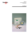
TTDM-128
TraceTek Leak Detection
�
Master Module
User Manual
TTDM-128
Table of Contents
Overview ......................................................................... 3
System Configurations ...................................................................3
Quick Setup..................................................................... 5
Common Setup Procedures ...........................................................5
Configuration Specific Setup ..........................................................7
Introduction..................................................................... 9
The TraceTek TTDM-128 Network ................................................9
Description of TraceTek Leak Detection System..........................10
TTDM-128 Features ...................................................... 11
Identifying TTDM-128 Features.................................................... 11
The TTDM-128 Keypad................................................................12
The TTDM-128 System Display ...................................................13
Normal Operation ......................................................... 14
Current Event/Status Display ......................................................14
Navigating the Menu Structure.....................................................14
Status of Individual SIM channels ................................................18
Modifying Settings for Individual SIM Channels ...........................20
Events History Log .......................................................................22
Detailed Setup............................................................... 23
General Set-up .............................................................................23
Leak Setup ...................................................................................24
SIM Network.................................................................................25
TTDM Network .............................................................................27
Self-Test .......................................................................................28
Event Response ........................................................... 29
Leak Detection and Location Events............................................29
Service Events .............................................................................30
Fault Events .................................................................................31
Multiple Events .............................................................................32
Maintenance.................................................................. 34
Appendix 1 - Events Glossary..................................... 36
Appendix 2 - Connection to Other Devices................ 37
H56853 12/03
2
Overview
TTDM-128
User Manual
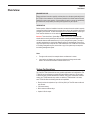
READ BEFORE USE
Please read these instructions carefully and keep them in a safe place (preferably close to
the TTDM) for future reference. The instructions provided in this booklet must be followed
carefully to ensure proper operation. If the equipment is used in a manner not specified by
the manufacturer, the protection provided by the equipment may be impaired.
PREPARATION
Before operation, follow the installation instructions to ensure that each module is properly
mounted and wired. If these steps have not been taken, refer to the installation documents
provided for each module. To obtain this literature or for technical assistance, contact your
local TraceTek distributor or visit our web site (http://www.tycothermal.com).
IMPORTANT: There should be a “System Map” for each sensor circuit. The system map
should show the sensing cable layout with reference to readily identifiable landmarks and
with actual distance measurements every 5 m (16 ft) throughout the system. The map is
normally completed at the time the leak detection system is commissioned. Ensure that a
copy of the system map is kept near the TTDM-128 module. If the TTDM-128 is connected
to a building management system, ensure that a copy of the system map accompanies
the building management system.
Notes
§
Throughout this manual, the examples shown use distances in meters.
§
Later versions of software may provide new features and change certain other
details. This manual documents UI software version 3.10i.
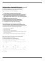
System Configurations
The TraceTek TTDM-128 module has many possible applications and configurations. The
TTDM-128 can be configured as a stand-alone leak detection panel, or it can be used in
a network of other TraceTek leak detection modules, such as the TTSIM sensor interface
module, the TT-NRM network relay module, or additional TTDM modules. In all cases,
each TTDM-128 offers the following features and capabilities:
§ Directly monitor the equivalent of up to 1500 m (5000 ft) of TraceTek sensor cable and
point sensors.
§ 1024 event memory.
§ Built-in status and alarm relays.
§ Optional 4-20 mA output.
H56853 12/03
3
TTDM-128 SINGLE CHANNEL STAND ALONE SYSTEM
(See Quick Setup on page 7)
§ TTDM-128 with up to 1500 m (5000 ft) of TraceTek sensor cable, or a combination
of sensor cable and point sensors.
SINGLE CHANNEL WITH REMOTE REPEATER
Primary TTDM
(Slave)
(See Quick Setup on page 7)
§ Stand-alone system with additional TTDM-128 acting as a remote display.
§ Remote panel mimics all conditions at the primary panel.
Remote Repeater
TTDM (Master)
§ Primary panel acts the same as a stand-alone TTDM-128 system.
RS-485 twisted
pair cabling
§ Modbus interface to a host computer is only available at the remote TTDM.
SINGLE TTDM-128 WITH NETWORK SYSTEM
Maximum of
126 TTSIMs
(See Quick Setup on page 8)
• A single TTDM-128 is used as the master module for a network of up to 126
additional TraceTek modules (TTSIM, TT-NRM).
Twisted
pair
network
Up to 1500 m (5000 ft)
sensing cable per TTSIM
MULTIPLE TTDM-128 WITH NETWORK SYSTEM
(See Quick Setup on page 8)
• The same as the single TTDM network system, except with additional TTDM-128’s
acting as slave modules.
• One TTDM-128 acts as the network master, the other TTDM-128’s act the same as
stand-alone systems.
• Additional TTSIM and TT-NRM modules can be installed on the network, up to a
total of 127 modules (including TTDM’s).
H56853 12/03
Add TTDMs into the SIM network
where it makes sense to have a local
display, relays, etc.
4
Quick Setup
TTDM-128
User Manual
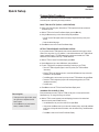
Common Setup Procedures
All modules, cables and sensors should be installed in accordance with their installation
instructions prior to performing the setup procedures.
BASIC TTDM-128 SETUP (FOR ALL CONFIGURATIONS)
► Power up the TraceTek system. Wait while the TTDM completes its self test and network
initialization process.
► With the TTDM on the Current Event/Status display, press the MENU key.
► Using the DOWN arrow key, scroll to General Setup and press ENTER.
▪ Set the Time and Date (adjust values as necessary using the arrow keys, then press
ENTER).
▪ Select the desired language.
► Press MENU to return to the Current Event/Status display.
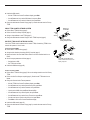
SETTING TTSIM ADDRESSES ON NETWORK SYSTEMS
If your system includes TTSIM modules, their network addresses must be set to unique
values in the range from 2 to 127 (address 1 is the default address of the TTDM’s internal
Sensor Interface board). If TT-NRM network relay modules are installed, the TTSIM
addresses must be different than any TT-NRM addresses.
► With the TTDM on Current Event/Status display, press MENU.
► Use the DOWN arrow key to select SIM Network, then press ENTER.
► For each TTSIM (perform complete procedure before continuing to next TTSIM):
▪ Place the TTSIM configuration jumper in the CFG position (see TTSIM Installation
Instructions).
▪ With the TTDM in the SIM Network menu, use the UP and DOWN arrow keys to select Set
SIM Address, then press ENTER.
▪ Press ENTER again, use the arrow keys to input the new TTSIM address, then press ENTER.
▪ Return the TTSIM configuration jumper to the normal operating position (see TTSIM
Installation Instructions).
▪ Press ESC twice.
► Press MENU to return the TTDM to Current Event/Status Display mode.
CHANGING LEAK CHANNEL ID TAGS
Time saving hint
▪ If the space to the right is blank, press
the right arrow to duplicate the last
letter entered
▪ Use the RESET key to jump between
letters, numbers and blank
Each leak detection channel (TTDM or TTSIM) can be given a unique alpha-numeric
identification tag. To change the ID tag of a channel:
► With the TTDM in normal operating mode and displaying the status of the desired leak
detection channel, press the DOWN arrow key:
▪ Use the DOWN arrow key to scroll to select ID, then press ENTER.
▪ Using the LEFT and RIGHT arrow keys to select the character position, and the UP and DOWN
arrow keys to change the letters and numbers, enter the desired ID tag. Press ENTER when
finished.
▪ Press MENU to return to the Current Event/Status Display.
H56853 12/03
5
CHANGING LEAK CHANNEL UNITS
The unit of measure for circuit length can be changed individually by channel, or for all
channels.
To change units for an individual channel:
► With the TTDM in the Current Event/Status Display and displaying the status of the desired
leak detection channel, press the DOWN arrow key.
► Use the DOWN ARROW key to select TestLength, then press ENTER.
► Use the UP/DOWN arrow keys to select the desired units (feet, meters or zones) then press
ENTER.
► Press MENU to return to the Current Event/Status Display.
To change units for all channels at once:
► A password is required to access the Special menu and change all units. To input the
password:
▪ With the TTDM in the Current Event/Status Display press the MENU key.
▪ Use the DOWN arrow key to select General Setup, then press ENTER.
▪ Use the DOWN arrow key to select Password, then press ENTER.
▪ Use the arrow keys to input the password 04000, then press ENTER.
▪ Press ESC.
► With the display showing the General Setup menu, use the DOWN arrow key to select Special,
then press ENTER.
► Use the DOWN arrow key to select Set All Units, then press ENTER.
► Use the UP/DOWN arrow keys to select the desired units (feet, meters or zones) then press
ENTER.
► Press MENU to return to the Current Event/Status Display.
SET HOST PORT PARAMETERS
For TTDM’s that are connected to a host computer, DCS or building management system,
the host port parameters must be set.
► With the TTDM in the Current Event/Status display, press MENU.
► Use the DOWN arrow key to select TTDM Network, then press ENTER.
► Use the DOWN arrow key to select the desired parameter, then press ENTER. If asked for a
password, input 00010 and press ENTER. The parameters that can be changed are:
▪ Baud: select host port baud rate.
▪ Modem: Define modem dialing strings.
▪ 485 Address: Set the TTDM’s MODBUS address.
▪ TTDM: Select the host port mode (Master or Slave). The password for this parameter is
04000.
NOTE: For communication with automation systems, PC’s and other host systems, set the
port to Master. Slave mode is used only for communication to a TTDM operating as a
Remote Display.
H56853 12/03
6
TTDM-128
User Manual
Configuration Specific Setup
STAND ALONE SINGLE CHANNEL SYSTEM
► Perform Basic TTDM-128 Setup (page 5).
► Assign the leak detection channel tag if required (page 5).
► Perform the Host Port Setup if required (page 6).
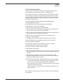
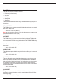
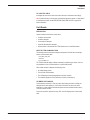
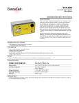
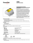
SINGLE CHANNEL WITH REMOTE REPEATER
Primary TTDM
(Slave)
Before powering up the system:
► Remove the internal Sensor Interface Board from the Remote Repeater TTDM.
► Connect the RS-485 host port (J13) of the Primary TTDM to the TraceTek Network port (J10)
of the Remote Display TTDM.
Remote Repeater
TTDM (Master)
RS-485 twisted
pair cabling
Remote Display (Master) TTDM
Primary (Slave) TTDM
J10
RS-485
485+
3
EXT
J13
XMTRS
485–
4
RS-232/485 EXT COM PORT
RX/A
TX/B
5
6
485+
485 –
Remote repeater RS-485 connection diagram
You can now power up the system and proceed with setup as follows:
At the Primary (Slave) TTDM
► Perform Basic TTDM-128 Setup (page 5).
► Assign the leak detection channel tag if required (page 5).
► Make sure that the Host Port Mode Selector Switch on the User Interface board is set to RS485.
► Set the host port parameters as follows (page 6):
▪ Set baud rate to 9600.
▪ Set TTDM mode to Slave.
At the Remote Repeater (Master) TTDM
► Perform Basic TTDM-128 Setup (page 5). Be sure the settings match those of the Primary
TTDM.
► Perform the Host Port Setup as required (page 6). Check that the TTDM mode is set to
Master.
► Change the Communication Timeout parameter:
▪ With the TTDM in the Current Event/Status display, press MENU.
▪ Use the DOWN arrow key to select General Setup, then press ENTER.
▪ Use the DOWN arrow key to select Password, then press ENTER.
▪ Input the value 04000, then press ENTER followed by ESC.
▪ Use the DOWN arrow key to select Special, then press ENTER.
▪ Use the DOWN arrow key to select Comm Timeout, then press ENTER.
▪ Use the arrow keys to input the value 300 ms, then press ENTER.
▪ Press MENU to return to the Current Event/Status display.
H56853 12/03
7
► Initialize the SIM network:
▪ With the TTDM in the Current Event/Status display, press MENU.
▪ Use the DOWN arrow key to select SIM Network, then press ENTER.
▪ Use the DOWN arrow key to select Init Network, then press ENTER.
► Change the leak detection channel ID tags (page 5) to match what was set at the Primary
TTDM.
SINGLE TTDM-128 WITH NETWORK SYSTEM
Maximum of
126 TTSIMs
► Perform Basic TTDM-128 Setup (page 5).
► Perform the Host Port Setup if required (page 6).
► Assign a unique address to each TTSIM (page 5).
► Change the leak detection channel ID tags for each TTSIM if required (page 5).
MULTIPLE TTDM-128 WITH NETWORK SYSTEM
Twisted
pair
network
Up to 1500 m (5000 ft)
sensing cable per TTSIM
One of the TTDMs must be selected as the master TTDM; all remaining TTDM’s in the
network will operate in “slave” mode.
At each slave TTDM:
► Perform Basic TTDM-128 Setup (page 5).
► Assign the leak detection channel tag (SIM ID) if required (page 5).
► Make sure that the Host Port Mode Selector Switch on the User Interface board is set to
RS485.
► Set the host port parameters as follows (page 6):
▪ Set baud rate to 9600.
Add TTDMs into the SIM network
where it makes sense to have a local
display, relays, etc.
▪ Set TTDM mode to Slave.
► Initialize the SIM Network (page 26).
At the master TTDM:
► Perform Basic TTDM-128 Setup (page 5). Be sure the settings match those of the Primary
TTDM.
► Perform the Host Port Setup as required (page 6). Check that the TTDM mode is set to
Master.
► Change the Communication Timeout parameter:
▪ With the TTDM in the Current Event/Status display, press MENU.
▪ Use the DOWN arrow key to select General Setup, then press ENTER.
▪ Use the DOWN arrow key to select Password, then press ENTER.
▪ Input the value 04000, then press ENTER followed by ESC.
▪ Use the DOWN arrow key to select Special, then press ENTER.
▪ Use the DOWN arrow key to select Comm Timeout, then press ENTER.
▪ Use the arrow keys to input the value 300 ms, then press ENTER.
▪ Press MENU to return to the Current Event/Status display.
► Initialize the SIM network (page 26).
► Change the leak detection channel ID tags (page 5) to match what was set at the Primary
TTDM.
H56853 12/03
8
Introduction
TTDM-128
User Manual
The TraceTek TTDM-128 Network
The TTDM-128 can directly monitor up to 1500 m (5000 ft) of TraceTek sensor cables,
up to 150 TraceTek point sensors and networks of up to 126 external TraceTek modules
(which can include any combination of TTSIM sensor interface modules, TT-NRM network
relay modules or up to 32 additional TTDM’s operating in slave mode). With a fully
implemented network, it is possible to monitor as much as 190 km (119 miles) of TraceTek
sensor cable and provide as many as 320 discrete relays to handle a wide variety of alarm
and telemetry functions.
NOTE: the maximum number of TTSIMs on a network must be reduced by 4 for each TTNRM added.
Each TTDM-128 provides:
▪ An internal Sensor Interface Module (SIM), capable of directly monitoring up to
1500 m (5000 ft) of sensor cable, 150 point sensors, or a combination of both cable
and sensors.
▪ 3 alarm relays, providing status for:
− Leak alarm
− Service required alarm
− System fault alarm
▪ Serial communication to a host computer, control system or building management
system using RS-232 or RS-485 hardware and the MODBUS™ protocol.
▪ Event history log
▪ Optional 4-20 mA output
When liquid is detected on any sensor, the TTDM-128 sounds an alarm, illuminates an
LED, closes relay contacts, and displays the channel number and location of the leak on
an LCD display. Each alarm event (leak, service, fault, etc.) and user action is logged into
the event history file. The event history file shows the type of event as well as the time
and date that the event occurred. This information is available to any host PLC or building
automation system via an RS232 or RS485 serial connection and the MODBUS protocol.
A simple system map (typically an as-built drawing of the sensor installation with reference
measurements) showing where the sensors have been installed is the only field calibration
requirement.
Each individual sensor circuit detects, locates, and tracks leaks independently from
the other circuits in the leak detection system. There is no loss of sensitivity and no remapping required after an initial leak is detected.
The TTDM-128’s internal SIM has been designed for use with the following TraceTek
sensing cables:
§
TT1000 (water)
§
TT3000 (Acids and Aqueous chemicals)
§
TT5000 (liquid hydrocarbon fuels and oils)
§
TT5001 (organic solvents)
A variety of TraceTek Point sensors, as well as contact closure devices such as float
switches, can also be used with the TTDM-128.
H56853 12/03
9
Description of TraceTek Leak Detection System
TRACETEK SENSING CABLES
The TraceTek leak detection system is based on sensing cables that detect liquid at
any point along their length. A variety of TraceTek sensing cables are available to detect
different types of liquids. While multiple types of sensing cables may be used in a single
sensing circuit, if different types of fluid are being monitored in the same area it may be
more effective to create multiple circuits, each with dedicated sensor cable of a specific
type.
COMPONENTS OF TRACETEK LOCATING SYSTEM
TraceTek leak detection is a versatile modular system, with interchangeable components
that can be configured in many different ways. For more information on the products and
systems available, consult the appropriate TraceTek product selection guide or your local
TraceTek representative.
����� ���
�������� ������
������� ���������
���������
������� ���
������� �����
�����������
������������� ��������
��������� �� ���
�� ������� �� ����
�� ����� �������
�������� �� ������
������� ������ �����
������� �����
����
��������� �����
������� ������ �����
������� ������ ���
���� ���������
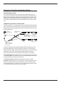
A TraceTek locating system provides distributed leak detection and location over long
distances and wide areas. A TraceTek locating circuit consists of a TraceTek locating
module (TTDM-128, TTSIM), sensing cable and/or point sensors, and circuit components
(leader cable, jumper cables, end terminations, weighted lengths, and branching
connectors) with connectors that allow components of the system to plug together.
The weighted length resistor simulates a 4.5 m (15 ft) length of sensing cable. Installed
at the boundary between two areas of sensing cable, the weighted length allows the user
to clearly identify the area where a leak has occurred.
The branching connector enables the sensing cable to be branched. An end
termination completes each branch. At the branching connector, the system first counts
the sensing cable along the branch (middle connector) to its end termination, before it
continues with the main run. Two built-in 4.5 m (15 ft) weighted-length resistors allow the
user to clearly identify the leg on which a leak has occurred.
H56853 12/03
10
TTDM-128
User Manual
TTDM-128 Features
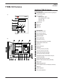
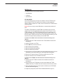
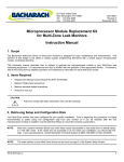
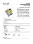
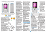
Identifying TTDM-128 Features
External View [A]
1
LCD display gives up-to-date information regarding the
condition of the system
A
TTDM-128
2
Icons and LEDs:
Monitoring LED - green
Service Required LED - Yellow
Leak LED - Red
Fault LED - Red
3
(Self) Test key
4
Silence key
5
Reset key
6
Menu keys
1
2
3
4
5
6
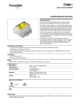
Internal View [B]
7
User interface (UI) board
(enlarged)
B
7
8
9
10
30
29
H56853 12/03
21
20
19
18
17
Power supply board
12
Fuse (500 mA, 250 V)
13
Power cable terminal block (removable)
14
Voltage selector 110/220 volts
16
Ground (earth) stud
17
Gland plate
13
18
Fault relay terminals (removable)
19
Leak relay terminals (removable)
20
Service relay terminals (removable)
21
4-20 mA port terminals (removable)
22
RS-232/485 external communications serial port
terminals (removable)
23
Sensing cable terminals (removable)
24
RS-485 TT-SIM network terminals (removable)
25
Ribbon cable
26
RS485/232 toggle switch
27
Test Port (DB-9 connector for temporary connection)
28
Reset pins
29
Volume adjustment
30
LCD contrast adjustment
16
22
Motherboard (MB)
11
12
15
23
Sensor Interface (SI) board
Spare fuse
14
24
9
10
15
27
25
4-20 mA board (optional)
11
28
26
8
11
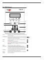
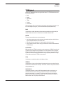
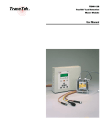
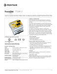
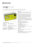
The TTDM-128 Keypad
TTDM-128
9
1
8
2
7
6
3
4
1. Test
5
Activates limited series of self-tests; additional self-tests are accessed through
the menu (see page 28).
2. Left/Right arrow In Current Events/Status display, manually select the channel displayed. When
inputing numbers or text, select digit to change. In menus, act as express keys
for going to the top or bottom of long scrolled lists.
3. Menu
Accesses menu of display and set-up options (see “Navigating the Menu
Structure” on page 14).
4. Esc
Goes back (up) one level in menu structure.
HINT: Pressing ESC multiple times returns to the Current Events/Status
display. From most menus, pressing MENU also returns to the Current Events/
Status display.
5. Enter
Selects a menu option or enter a user supplied value.
6. Down arrow
In Current Events/Status display, accesses detailed System Status
information for the channel currently displayed (see page 14 for details). In
menu selections, scrolls down through displays and menu options. Change
(decrease) digits or alpha characters when entering user supplied values.
7. Up arrow
Scrolls up in status displays and menu options. Change (increase) digits or
alpha characters when entering user supplied values.
8. Reset
Resets the Leak alarm relay, including TTSIM-1A relays and TT-NRM relays.
9. Silence
Silences the audible alarm.
H56853 12/03
12
TTDM-128
User Manual
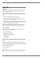
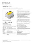
The TTDM-128 System Display
The icons represent the four conditions of the leak detection network. The LEDs indicate
which conditions are currently active.
Green
Yellow
Red
Red
Monitoring
Service
Leak
Fault
NOTE: The Service, Leak and Fault LEDs will illuminate if an alarm condition exists on any
SIM. Multiple LEDs may be illuminated simultaneously to indicate multiple types of alarms,
although the alarms could exist on different SIM channels.
MONITORING
This green LED indicates that the TTDM-128 is powered up.
SERVICE
The TTDM-128 is able to give advance warning of potential problems. The yellow Service
LED illuminates to indicate that service is required on one of the sensing cables attached
to the network. Note that the green Monitoring LED remains illuminated; the unit continues
to monitor for leaks during a Service alarm.
LEAK
When liquid is detected, the red Leak LED illuminates. Note that the green LED remains
illuminated; the unit continues to monitor for new leaks on all channels, as well as for
changes to the detected leak.
FAULT
When the TTDM-128 module detects a fault — either a cable fault (break) or an
electronics fault — the red Fault LED illuminates. After a fault on an individual SIM has
been detected, the TTDM-128 module will, in most cases, continue to scan the remaining
SIM units and their associated sensing circuits. However, some fault conditions may
disable multiple channels or even the entire system. The TTDM-128 is unable to detect a
leak on any channel affected by a fault.
IMPORTANT: Always investigate the cause of a Fault condition immediately.
NOTE: For more information on the various TTDM-128 alarm states, see the Event
Response section of the manual on page 29.
H56853 12/03
13
Normal Operation
Current Event/Status Display
Line 1
CH01 SERVER ROOM
Line 2
LEAK AT 125 M
Line 3
Line 4
12 :30 21-01-2003
The LCD display is a backlit 4-line by 20-character display. If there is no activity for several
minutes, the back lighting turns off, until a key is pressed.
Line 1
identifies the channel currently displayed, showing the SIM channel
number and user-defined ID tag (up to 14 characters). For a new
system, the user-defined label is blank until edited by the user (see
page 5).
Line 2
indicates the current status of the SIM channel identified on Line 1,
or
In the case of Leak re-alarm, displays the initial leak location of the
SIM channel identified on Line 1.
Line 3
may advise action or provide special instructions,
or
in the case of leak re-alarm, indicates the current status of the SIM
channel identified on Line 1.
Line 4
displays the current time (in 24 hour format) and date; the colon
blinks once a second,
or
in the case of Leak re-alarm may advise action or provide special
instructions.
HINT: The LCD contrast may be adjusted (feature 30 in the diagram on page 11).
If no new alarm conditions exist, the LCD display scrolls through each connected SIM
channel in sequence. The LCD presents the current event/status display for each channel
for about 4 seconds, then continues to the next available SIM channel. Once the last SIM
channel is displayed, the process starts again at the first channel.
If the TTDM detects a new Service, Fault, or Leak event, it immediately jumps the display
to the SIM channel affected, turns on the LCD back light, and pauses at that channel
number for several minutes.
NOTE: Use the left and right arrow keys to manually select the channel displayed.
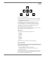
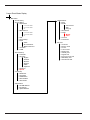
Navigating the Menu Structure
Please refer to the “Menu Structure” diagram on page 16 for an overview of the TTDM-128
menu structure. Refer to the diagram on page 12 to locate the menu keys described below:
H56853 12/03
14
TTDM-128
User Manual
From the Current Event/Status display:
► Press the LEFT and RIGHT arrow keys to manually select the channel you require displayed.
► Press the DOWN arrow key to access detailed status information for the channel currently
displayed described in detail on page 18.
► Press the MENU key to access the many display and setup features in the TTDM.
► Use UP and DOWN arrow keys to scroll through menu options and status displays.
► Use the LEFT and RIGHT arrow keys to select individual characters when entering data.
► Press ENTER to make a selection or go one level deeper into the menu structure.
► Press ESC to go back (up) one level in the menu structure.
NOTE: If the TTDM-128 is left in a menu display with no keypad activity for 30 minutes, it
automatically returns to the Current Event/Status display.
MENU OPTIONS
The following are the options presented at the Main Menu level:
▪ Event History
▪ System Status
▪ General Setup
▪ Leak Setup
▪ SIM Network
▪ TTDM Network
▪ Self-Test
Each of these menu items is described in detail on the following pages.
ENTERING A PASSWORD
When a user attempts to change a restricted setting, the TTDM-128 displays a password
prompt. The factory default password is 00010 (to change the password, see page 23). To
enter the password, proceed as follows:
▪ Use the LEFT and RIGHT arrow keys to move to each digit.
▪ Use the UP and DOWN arrows to increase/decrease the selected number.
▪ Press ENTER when complete.
NOTE: Once the password is entered, it remains in effect (allowing access) until the user
exits the main menu and returns to the Current Event/Status display, or until there has
been no keypad activity for approximately 30 minutes.
H56853 12/03
15
Current Event/Status Display
Menu
---- Main Menu
---- Events History
---- System Status
---- SIM network
---- 1..current status
---- 2..current status
---- #...
---- NRM Network
---- 1..current status
---- 2..current status
---- #...
---- Leak
---- Service Reqd
---- Faults
---- Cable
---- SI Comm/Other
---- NRM Comm Error
---- UI Version
---- TTDM
---- General Setup
---- Time/Date
---- Language
---- English
---- Francais
---- Deutsch
---- Espanol
---- Italian
---- Japanese
---- Password
---- Special
---- Leak Setup
---- ReAlarmInt
---- Auto Reset
---- AudibleAlarm
---- Alarm Reflash
---- Alarm Reset
TTDM Network
---- Baud
---- Modem
---- Auto Answer
---- Dial
---- Hang up
---- 485 Address
---- TTDM
---- Master
---- Slave
---- Terminal
---- Print Events
---- Self-Test
---- UI Version
---- Memory Tests
---- SI Test
---- 4-20 mA Test
---- Display Test
---- UI Relay Test
---- Keypad Test
---- Ext Comm Loop Test
---- NRM Relay Test
---- Ground Fault Test
---- SIM Network
---- Set SIM Address
---- Init Network
---- Update Network
H56853 12/03
16
TTDM-128
User Manual
Current Event/Status Display
---- SIM Status
---- SIM Address
---- select different SIM
---- ID
---- change SIM ID
---- current status
---- last alarm value
---- TestLength
---- feet
---- metres
---- zones
---- Sense Cur
---- Location
---- Loc Res
---- Serv Alert >=
---- Set Service Alert
---- Normal (50 uA)
---- High (20 uA)
---- Low (80 uA)
---- TT500x (40 uA)
---- Never
Add Regions/Relays
---- Region #
---- Start
---- End
---- Id
---- Region Relay
---- Trouble Relay
---- Service Relay
---- SIM Relay
(only appears for TTSIM-1A)
---- Alarm Mode
---- Leak
---- Leak/Brk
---- Alarm State
---- OFF
---- ON
---- Relay Reset
---- Auto
---- Manual
---- Safe
---- Sense Res
---- Leak Alarm <=
---- Set Leak Alarm
---- Normal (18 k�)
---- High (30 k�)
---- Low (14 k�)
---- TT500x (10 k�)
-------------
R-G Res
Y-B Res
SI Version
SI Comm
Legend:
normal text = menu item
italic text = variable data
bold text = password required
H56853 12/03
17
Status of Individual SIM channels
The TTDM-128 offers access to detailed real-time status information for each SIM
channel. The status display for an individual SIM channel is accessed from the Current
Event/Status display:
► If in a menu, press ESC one or more times (or press MENU) to return the Current Event/Status
display.
► Use the LEFT or RIGHT arrow keys to select the SIM channel of interest.
► Press the DOWN arrow to access the detailed status information (as shown below) for the
selected channel.
SIM Status
SIM Address
ID
SIM Status
TestLength
Sense Cur
Serv Alert >=
Sense Res
Leak Alarm <=
R-G Res
Y-B Res
SI Version
SI Comm
Add Regions/Relays
address
user defined ID
xxxx m
xxx uA
xx uA
xxxxx kΩ
xx kΩ
xxxxx Ω
xxxxx Ω
xxxx
xxx%
NOTE: Only four lines are displayed at one time. Arrows in the scroll bar indicate if other
entries can be accessed with the up or down arrow keys.
A description of each line on the SIM Status Menu appears below:
SIM Address
Channel number for information in current display
ID
An alphanumeric label specified by the user (maximum 14
characters).
SIM status
SIM Status can contain any of the following text, depending on
the state of that SIM channel:
▪
▪
▪
▪
▪
▪
Test Length
SIM Normal
Leak {location}
Re-alarm [new location]
Service Required [location]
Leak cleared
Cable break
Total length of sensing cable attached to the selected SIM.
The test length should be the same as that recorded when
the channel was mapped. If the length is not the same, it
may mean that the system was modified (sensing cable was
removed or added).
NOTE: The Test Length is typically about 1% longer than the
physical or mapped length for the channel; this is normal.
H56853 12/03
18
TTDM-128
User Manual
H56853 12/03
Location
The current location — or electrical center — of the leak (or
cause of a Service alarm). If the SIM status is Normal, the
Location entry is blank.
Sense Cur
This current (measured in µA) indicates the condition of the
sensing cable. If a leak is detected in the channel, this rises to
270 µA or more (depending on the type of TTSIM). In a clean,
leak-free sensing circuit, the current should be 5 µA or less. If
the current rises above 20 µA, service is recommended, as it
may indicate the presence of contamination.
Serv Alert >=
This setting controls Service Required Alarms. If Sense Cur is
greater than this value, the TTDM signals a Service Alarm.
Sense Res
This is the resistance measured between the sensing wires.
For a clean, leak-free sensing circuit, this resistance is more
than 20000 kΩ. If liquid is detected, it will drop to less than 30
kΩ. If the resistance is changing, it may indicate an event in
progress.
Leak Alarm <=
This setting controls Leak Alarms. If Sense Res drops below
the threshold level, the TTDM signals a Leak Alarm.
R-G Res,
Y-B Res
These are the resistances of the Red-Green and Yellow-Black
loops in the TraceTek sensing circuit. If these values are
significantly different from each other, the TTDM will signal a
Loop Imbalance alarm, indicating damage to a sensing cable
or connector.
SI Version
This indicates the software version operating in the SIM
microprocessor.
SI Comm
This indicates the success rate (in percent) for
communications between the TTDM-128 and the SIM channel
selected. A value below 90% may indicate a faulty connection
or damaged RS-485 cable.
Add Regions/Relays
This menu item accesses a submenu that lets the user divide
a length of sensing cable into as many as 10 smaller logical
sections (regions) and assign relays to those regions. Dividing
a length of cable into regions can help the user identify the
location of an alarm condition. By assigning relays to regions,
it is also possible to create a wide range of alarm actions
depending on the region and sensor condition. See Setting Up
Regions, page 21.
19
Modifying Settings for Individual SIM Channels
To change the alphanumeric tag for the selected SIM channel:
► Select the appropriate SIM channel as described previously in this section.
► Use the DOWN arrow key to select ID, then press ENTER.
► Use the LEFT and RIGHT arrows to select a character position to modify.
Tip: Use the RESET key to “tab” between Letters, Numbers, and blank.
► Use the UP and DOWN arrows to cycle through all available characters until the desired
character is displayed. There are numerous punctuation, currency, Katakana, and nonEnglish alphabetical characters available. Going “up” or “down” cycles through all available
characters.
► Press ENTER once the label has been set up as desired.
To change the length units for the selected SIM channel:
► Select the appropriate SIM channel as described previously in this section.
► Use the DOWN arrow key to select Test Length, then press ENTER.
► Use the DOWN arrow key to select the desired units, then press ENTER.
CHOOSING APPROPRIATE LEAK ALARM AND SERVICE REQUIRED LEVELS.
Leak sensitivity and Service Required levels should be based on the type of liquid being
detected and the environment in which the sensing cable is installed.
▪ Normal (default) for most applications.
▪ High for de-ionized water.
▪ Low for particular active or exposed applications.
▪ TT500x for systems using hydrocarbon-sensing cable (TT5000, TT5001) to monitor
doublewall pipes and tanks.
▪ Never (only available for Service Required setting) to disable the Service Alarm.
NOTE: Password is required to change leak and service sensitivity settings.
To change the leak alarm sensitivity:
► Select the appropriate SIM channel as described previously.
► Use the DOWN arrow key to select Leak Alarm <=, then press ENTER. If a password is
requested, input the value 00010 then press ENTER.
► Use the UP/DOWN arrow keys to choose a sensitivity level (Normal, High, Low or TT500X),
then press ENTER.
To change the Service Required setting:
► Select the appropriate SIM channel as described previously.
► Use the UP/DOWN arrow keys to select Serv Alert >=, then press ENTER. If a password is
requested, input the value 00010 then press ENTER.
► Use the DOWN arrow key to choose a Service Alert level (Normal, High, Low, TT500X, or
Never).
► Press ENTER.
H56853 12/03
20
TTDM-128
User Manual
SETTING UP REGIONS AND RELAYS
For some systems, it may be helpful to divide a circuit of sensing cable into regions. In
addition, regions are sometimes useful in setting up TT-NRM relay actions.
When a length of sensing cable is divided into regions, the TTDM will identify the region
in which a Service or Leak event occurs. Each region represents a section of the entire
length of sensing cable. Regions are defined by a low limit (starting distance) and a high
limit (ending distance). Regions can contain the entire circuit, or only a part of the circuit,
and they may overlap each other.
To create regions for a circuit (repeat for each desired region):
► Select the appropriate SIM channel.
► Use the DOWN arrow key to select Add Regions/Relays, then press ENTER.
► Select Region No. from the menu and press ENTER.
► Use the arrow keys to select a region (1-10) and press ENTER.
► Select Start from the menu and press ENTER. This value represents the starting distance for
the region. Using the arrows, enter a low limit and press ENTER.
► Select End from the menu and press ENTER. This value represents the ending distance for the
region. Using the arrows, enter a high limit and press ENTER.
► Select ID from the menu and press ENTER. Using the arrows, assign the region an
alphanumeric tag and press ENTER.
If a TT-NRM is connected and will be utilized with this region, continue as follows.
NOTE: Each TT-NRM relay can only be assigned to a single region and a single function.
► Select Region Relay and press ENTER.
► Using the arrows, assign the relay to be activated for a Leak Alarm. Press ENTER.
► Repeat this process for the Trouble Relay and Service Relay.
If the SIM is a TTSIM-1A or TTSIM-2, continue as follows:
► Select SIM Relay and press ENTER.
► Select Alarm Mode and press ENTER. Select Leak if you want the relay to activate only on leak
alarm, or select Leak/Brk if you want the relay to activate for any sensor alarm condition, then
press ENTER.
► Select Alarm State and press ENTER. Select OFF if you want the relay to be normally
energized and de-energized for alarms, or select ON if you want the relay to be normally deenergized and energized for alarms. Press ENTER.
► Select Relay Reset and press ENTER. Select the appropriate reset mode, then press ENTER:
▪ Auto: the relay will reset when the TTDM Reset key is pressed (regardless of the current
alarm condition), or it will automatically reset when the alarm condition clears.
▪ Manual: the relay will reset only when the TTDM Reset key is pressed. The relay will reset
regardless of the current alarm condition.
▪ Safe: the relay will reset only when the alarm condition has been cleared and the TTDM
RESET key is pressed.
NOTE: TTSIM-1A and TTSIM-2 relays will activate for any leak on the circuit, regardless of
region definitions.
H56853 12/03
21
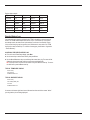
Region setup example:
Region No.
1
2
3
4
Low Limit
0m
251 m
501 m
751 m
High Limit
250 m
500 m
750 m
1,000 m
ID
Room A
Hall
Room C
Room D
Region relay
50-01
50-02
50-03
50-04
Trouble relay
50-06
50-06
50-06
50-06
Service relay
50-07
50-07
50-07
50-07
Events History Log
One extremely useful function provided by the TTDM is the ability to record a series of
events. The TTDM module keeps track of a list of up to 1,024 events (if 1,024 events
are already stored, the oldest event is discarded as a new event is recorded). Events
in the events history log may be specific to one SIM channel or may refer to the TTDM
itself (such as user interactions). For a full list of event types, please refer to “Appendix 1
- Events Glossary”.
ACCESSING THE EVENTS HISTORY LOG
► From the Current Events/Status display, press MENU
► Use the arrow keys to select Events History, then press ENTER.
► Use the UP and DOWN arrow keys to scroll through the events history log. The events will be
displayed in chronological order, with the most recent event displayed first.
HINT: To quickly move to a view of the most recent event, press the LEFT arrow key. To move to
the oldest event, press the RIGHT arrow key.
TYPICAL TTDM EVENT DISPLAY
Events History
Alarm Silenced
HH:MM DD-MON-YYYY
TYPICAL SIM EVENT DISPLAY
Events History
CH01 USER_LABEL_0001
Leak 237 ft
HH:MM DD-MON-YYYY
An arrow at the bottom right-hand corner indicates that there are further events “below”
(occuring before) the one being displayed.
H56853 12/03
22
Detailed Setup
TTDM-128
User Manual
General Set-up
Access the General Set-up menu from the Main Menu. The General Set-up menu has the
following sub menus:
▪ Time/Date
▪ Language
▪ Password
▪ Special (High level password required to see this menu)
TIME/DATE
Use the LEFT and RIGHT arrow keys to select each digit. Use the UP/DOWN arrow keys to
increase or decrease the number.
LANGUAGE
Select from available options (English, Français, Deutsch, Espanol, Italian and Japanese).
PASSWORD
Entering a Password
When the user attempts to change a restricted setting, a password prompt appears.
► Use the LEFT and RIGHT arrow keys to move to each digit.
► Use the UP and DOWN arrow keys to increase or decrease the number.
► Press ENTER when complete.
The TTDM is supplied from the factory with the password 00010.
Changing the Password
► Enter the old password if requested.
► Enter the new password (using the arrow keys) and press ENTER.
HINT: If password protection is not required, set the password to 00000. After that, you will
not be prompted for a password.
H56853 12/03
23
Leak Setup
The Leak Setup menu has the following submenus:
▪ ReAlarm Int (Re-Alarm Interval)
▪ Auto Reset
▪ AudibleAlarm
▪ Alarm Reflash
▪ Alarm Reset
These parameters determine the alarm setting for all SIMs. Password entry is required to
change them.
RE-ALARM INTERVAL
The TTDM can be set to re-alarm automatically if the alarmed event has not been cleared
after a certain length of time.
− allowed range: 0 – 24 hours (default = 0)
HINT: Use this to automatically alert the next shift when the system has an uncleared event
(leak, cable break/fault, or service required).
AUTO RESET
The TTDM is factory set to require a manual reset following a leak event. This allows the
user to verify that any equipment connected to the Leak relay is ready to be switched back
to its normal state. Note that this setting is independent from the TTSIM-1A/TTSIM-2 relay
reset mode.
If Auto Reset is set to “On,” the leak relay will automatically reset as soon as the leak has
been cleared.
− choices: Off / On (default: Off)
AUDIBLE ALARM
The audible alarm may be disabled if not required. See feature 29 on page 11 to adjust the
volume.
− choices: Off / On (default: On)
ALARM REFLASH
The alarm reflash option causes the leak alarm relay contacts to revert to their no-alarm
state for approximately 5 seconds then return to the alarm state whenever an additional
leak occurs before an existing leak is cleared. This is useful when a multi-channel system
is connected to a host computer via a simple relay-only interface. Reflash will typically
cause the host computer to log each new leak event as it occurs whether or not preceding
events have been cleared.
− choices: Off / On (default: Off)
ALARM RESET
This parameter determines whether all SIM channels will be reset simultaneously when
the Reset key is pressed (All setting), or only the currently displayed SIM channel will be
reset (Single setting).
− choices: Single / All (default: Single)
H56853 12/03
24
TTDM-128
User Manual
SIM Network
The SIM Network menu has the following submenus:
▪ Set SIM Address
▪ Init Network
▪ Update Network
SET SIM ADDRESS
This command allows the user to assign a new address to either the TTDM’s internal
SIM or an external TTSIM. This function is vital to starting up a new leak detection
network. To assign an address to a TTSIM, it must be connected to the TTDM and able to
communicate with it.
IMPORTANT: Be sure to assign a unique SIM address, or communications problems will
result.
To set SIM or TTSIM addresses, the SIM/TTSIM to be addressed must be set to the
configure mode. This is accomplished by placing a jumper on the CFG pins (J1 on the
TTDM’s internal SIM – see TTDM-128 Installation Instructions for details; refer to the
appropriate TTSIM installation instructions for details regarding external TTSIM’s). Note
that only 1 SIM or TTSIM can be set to CFG at a time. After setting the address, you must
remove the CFG jumper before proceeding to the next SIM/TTSIM.
To add a new TTSIM to the leak detection network and assign it an
address
► Install and connect the TTSIM in accordance with the TTSIM Installation Instructions that
accompanied it.
► Install the CFG jumper on the TTSIM.
► Press the MENU key to access the main menu.
► Select SIM Network and press ENTER.
► Select Set SIM Address and press ENTER.
► Select New Address and press ENTER.
► Use the arrow keys to set the new address to an unused address between 001 and 127 (note
that address 001 is the factory default for the TTDM’s internal SIM) and press ENTER.
► Remove the CFG jumper clip from the TTSIM, then press ESC twice on the TTDM.
► Repeat as necessary for each TTSIM added to the network.
To add a new TT-NRM to the leak detection network and assign it an
address
► Install and connect the TT-NRM in accordance with the Installation Instructions that
accompanied it.
► Using the switches on the TT-NRM base unit, select a unique address (see TT-NRM
Installation Instructions). The address must not be used by any other device on the network.
► Power up the system and perform a network Update or Initialization (see INIT NETWORK
and UPDATE NETWORK, page 26).
► Configure relay assignments (see SETTING UP REGIONS AND RELAYS, page 21).
H56853 12/03
25
UPDATE NETWORK
Use this command to update the TraceTek network when TTDM, TTSIM or TT-NRM units
have been added and assigned unique addresses (this is not necessary when TTSIM’s
are added and addressed using the TTDM Set SIM Address menu - see page 5). When
activated, this command immediately searches all possible addresses to determine what
equipment has been connected. The current event status of all devices will be maintained
by this command.
NOTE: Use the INIT NETWORK command to reset all current event status information.
► Select SIM Network and press ENTER.
► Select Update Network and press ENTER.
INIT NETWORK
Use this command to initialize the TraceTek network once all TTDM, TTSIM and TTNRM units have been connected and assigned unique addresses. When activated, the
Init Network command immediately searches all possible addresses to determine what
equipment has been connected. The current event status of all devices will be reset by
this command.
NOTE: Use the Update Network command to update an existing network without resetting
the status of existing SIM’s.
► Select SIM Network and press ENTER.
► Select Init Network and press ENTER.
IMPORTANT: For Master/Slave networks, the TTDM-128 configured as the Slave device
must be initialized or updated before the Master unit.
H56853 12/03
26
TTDM-128
User Manual
TTDM Network
Access the TTDM Network menu through the Main Menu. The TTDM Network menu has
the following submenus:
▪ Baud
▪ Modem
▪ 485 Address
▪ TTDM
▪ Terminal
▪ Print Events
These parameters affect only the serial port for external communications (features 22, 26
& 27 in the diagram on page 11). The first four submenus require password entry.
BAUD
Use this option to select the baud rate of the external communications (host) serial port.
Standard values are from 600 to 19200 baud are available. Default is 9600.
MODEM
This menu item provides access to three submenus:
▪ Auto Answer causes a text string to be sent to the external serial port, which will set a
Hayes compatible modem to auto answer mode.
▪ Dial allows the user to program an 11-digit numerical string into the menu.
▪ Hang-up allows the user to send a hang-up command to an external modem attached
to the serial port.
485 ADDRESS
When more than one TTDM is connected to a host computer on an RS-485 network, each
TTDM unit must be assigned a unique address. This menu allows the user to assign the
TTDM an RS-485 address (the default address is 1). An address of 1 through 20 hex can
be selected, however, 20 should be reserved for testing only. Using addresses 1 through
1F hex allows as many as 31 TTDM’s on one network.
TTDM
Use this menu to select this module to be a Master or Slave.
TERMINAL
Use this option to view a one-line display of characters being sent to or received from the
TTDM external communications serial port. This function is used to verify communications
during system start-up.
PRINT EVENTS
Use this menu selection to send an ASCII text message through the serial port to an
attached serial device (either a directly connected PC running a terminal-emulation
program, a serial printer, or a modem). This function allows the user to download all
events in the Event History Log for later analysis. Do not use this when connected to a
Modbus network, as it may disrupt communications.
H56853 12/03
27
Self-Test
The Self-Test menu provides access to specific user-selected test routines:
▪ UI Version
▪ Memory Tests
▪ SI Test
▪ 4-20 mA Test (see “Appendix 2 - Connection to Other Devices” for details)
−
Electronics Fault
−
SI Comm Error
−
Cable Break
−
Loop Imbalance
−
Service Req’d
−
System Normal
−
Leak (user selects location)
−
20 mA Val (user selects location)
−
4-20 mA SIM
▪ Display Test
▪ UI Relay Test (tests the TTDM’s internal relays)
▪ Keypad Test
▪ Ext Comm Loop Test (see “Appendix 2 - Connection to Other Devices” for details)
▪ NRM Relay Test (tests the relays on any connected TT-NRMs)
▪ Ground Fault Test
The Self-Test menu is password-protected to prevent inadvertent emergency response
activity, because in many installations the leak relay or 4-20 mA output may be connected
to external systems. Always notify the appropriate response personnel before using the
Relay Test or 4-20 mA Test to alter their outputs.
The first three tests are also accessed by pressing the Test key when the display is in the
Current Event/Status Display mode. This key is not password protected.
H56853 12/03
28
Event Response
TTDM-128
User Manual
Leak Detection and Location Events
A LEAK ALARM
When liquid is detected by a sensor in any channel, the following occur:
▪ The audible alarm sounds (If audible alarms are not required, the module can be set to
disable them - see page 24).
▪ The red Leak LED illuminates.
▪ The display changes to show the channel and location of the leak.
CH01 USER_LABEL_0001
Leak 504 m
hh:mm DD-MMM-YYYY
▪ The interfaces signal the event (Leak relay, 4-20 mA, and serial port)
The following actions should then be taken:
► Silence the alarm (if necessary).
► Locate the leak and clear the system.
► Reset the leak relay. (This occurs automatically if Auto-Reset is enabled; see page 24.)
TO LOCATE THE LEAK
Using the channel number and location displayed by the TTDM-128, refer to the system
map and determine where the leak was detected.
TO CLEAR THE SYSTEM
Fix the leak and clean up the area affected. Then clean and dry the sensing cable (in the
case of TT1000 and TT3000) or replace the affected section (TT5000/TT5001 series).
Once the sensing cable is clear, the module responds and the display changes:
CH01 USER_LABEL_0001
Leak Cleared
Press reset
hh:mm DD-MMM-YYYY
Notice that the red LED remains on. This indicates that the leak relay is still in the alarm
state.
TO RESET THE LEAK RELAY
In order to reset the leak relay and return the module to the “SIM Normal” state, press the
Reset button. Before doing so, check that any external equipment controlled by the leak
relay is ready to be reset.
Once the RESET button is pressed, the relay returns to normal, the red Leak LED
extinguishes, and the LCD returns to the normal display.
HINT: If manual reset is not required, the TTDM-128 can be set to auto-reset; see page 24.
H56853 12/03
29
Service Events
INTRODUCTION
A TraceTek sensing circuit consists of two electrical loops. The SIM module constantly
monitors for current passing between loops. When the system is normal, there is no
current passing between the loops.
When there is a leak on the system, the maximum current flows. If a SIM detects a lower
but significant level of current flow between the loops, the TTDM will signal a Service
Alarm.
A low-level current could indicate one or more of the following:
▪ A very small leak (which may soon develop into a full leak alarm).
▪ Heavy condensation or small spills (coffee, tea, etc.) on a water or aqueous solutions
sensing cable (TT1000 and TT3000 for example).
▪ Conductive material on a water or aqueous solutions sensing cable. The material might
be metal filings, concrete dust, flux, mastic, or other construction debris, or carbonbased dust from air-handling units, printers, or copiers.
While service alarms should be investigated, they do not threaten the operation of the
system. The TTDM and TTSIM will continue to detect leaks during a service alarm.
However, service alarms may affect the accuracy of leak location in certain cases.
THE SERVICE ALARM
When the TTDM detects a condition requiring service (such as described above), it
signals the event by taking the following actions:
▪ Sounds an intermittent beep.
▪ Illuminates the yellow Service LED.
▪ Switches the service relay to alarm state.
▪ Changes the LCD display to the following:
CH01 USER_LABEL_0001
Service Req’d [147]
hh:mm DD-MMM-YYYY
The number in square brackets indicates the estimated location of the material causing
the alarm. The number is shown with square brackets to indicate that the value is only an
estimate.
HINT: Because the cause (concrete dust, for example) of low-level current may be
distributed over a long length of sensing cable, it is not always possible for the TTDM-128
to report an accurate location. However, the indicated location is always a good point from
which to begin a troubleshooting procedure.
The following actions should be taken:
► Silence the audible alarm.
► Clear the cable.
NOTE: When the cable is cleared, the yellow Service LED, the alarm relay, and the LCD
display will automatically return to their normal (non-alarm) state. No reset is required.
H56853 12/03
30
TTDM-128
User Manual
TO CLEAR THE CABLE
Investigate the cause of the alarm and conduct cleanup or maintenance accordingly.
HINT: If material causing a service alarm is spread throughout the system, it is often useful
to subdivide the system; see INVESTIGATING LEAKS AND FAULTS on page 35 for
further information.
Fault Events
INTRODUCTION
Several conditions could lead to a fault alarm:
▪ A cable is disconnected.
▪ A cable is damaged.
▪ A connection is damaged.
▪ A specific SIM module is damaged.
▪ Communication is lost between the TTDM-128 and one or more SIM modules.
WHAT THE TTDM-128 MODULE DOES
The following shows how the alarm display would appear if the fault were caused by a
broken or disconnected cable:
CH01 USER_LABEL_0001
Cable Break
hh:mm DD-MMM-YYYY
The TTDM-128 would display a different message for a different type of fault, such as a
loop imbalance or loss of communication to a specific SIM module.
When a fault condition is detected, the following occur:
▪ An audible alarm sounds.
▪ The red Fault LED illuminates.
▪ The LCD displays a message appropriate to the fault condition.
▪ The interfaces signal the event (Fault relay, 4-20 mA, and serial port).
TO REMEDY THE PROBLEM
Find the problem and rectify it. This may mean reconnecting the cable, or finding the
damaged section and replacing it. If the cause of the fault is not obvious by visual
inspection, it is often useful to subdivide the system and test individual sections with a
TraceTek Portable Test Box.
As soon as the fault is rectified, the relay, LED, and LCD display return to their normal
state.
H56853 12/03
31
Multiple Events
SIMULTANEOUS EVENTS ON DIFFERENT SIM CHANNELS
The TTDM-128 is capable of monitoring many sensing circuits. Each SIM operates
independently of other SIMs in the leak detection network. The TTDM-128 tracks
information for all SIM channels and is capable of handling multiple events that occur in
the same time frame. Any new event takes precedence on the LCD display. The LCD
display will pause temporarily on the most recent event, giving the local operator time to
read the LCD message and take action. After pausing several minutes on the most recent
event, the TTDM-128 display resumes automatic scrolling through each connected SIM
channel.
At any time, the operator may manually select a channel by using the left or right arrow
keys. When a channel has been selected manually, the display pauses on the selected
channel for several seconds before scrolling resumes.
MULTIPLE EVENTS ON A SINGLE SIM CHANNEL
In some circumstances, multiple events may occur on a single SIM channel. The system
continues to monitor during Service and Leak alarms, ensuring that the installation
provides full-time protection. The TTDM-128 stores all events in memory, and in addition,
updates the display based on the sequence of events in a SIM channel.
MOVING LEAK
The TTDM will re-alarm when the leak moves more than the re-alarm distance, for which
the default is 2 m (5 ft). The audible alarm will sound, the third line of the LCD will change,
and a new event will be added to the Events History.
Example: suppose an initial leak is detected at 110 m. The TTDM would display:
CH01 USER_LABEL_0001
Leak 110 m
hh:mm DD-MMM-YYYY
Suppose also that before repairs can be made, the leak spreads. Once the module has
detected significant movement of the leak, the TTDM-128 module goes into alarm once
again:
CH01 USER_LABEL_0001
Leak 110 m
Re-Alarm 115 m
hh:mm DD-MMM-YYYY
The LCD now displays the first leak (on the second line of the display) and the most
recent alarm on the third line. The first leak recorded on the SIM channel is likely to be
close to the source of the leak. The most recent leak shows the current “electrical center”
of the liquid (essentially a weighted average). If the Re-Alarm location is relatively close to
the first (as in the example above), it is likely that the leak has spread.
Should the leak continue to spread, the TTDM would re-alarm again and the re-alarm
location is updated accordingly:
CH01 USER_LABEL_0001
Leak 110 m
Re-Alarm 120 m
hh:mm DD-MMM-YYYY
H56853 12/03
32
TTDM-128
User Manual
HINT: Use the Events History to track the events between the “first leak” and the “most
recent event.” See “The Events History Log” section on page 22.
ADDITIONAL LEAK
If liquid contacts sensing cable at a significant distance from the initial leak, the module
will re-alarm however it will indicate that this realarm leak distance could be caused by a
new leak rather than a growing leak. In this case, the TTDM shows the re-alarm location in
square brackets:
CH01 USER_LABEL_0001
Leak 370 m
Re-Alarm [205]
hh:mm DD-MMM-YYYY
Brackets indicate that the value shown requires interpretation; when an additional leak
occurs, the value represents the “electrical center” of the leaks.
SERVICE-TO-LEAK ALARM
Although the TTDM-128 and TTSIM system can continue to monitor a channel when a
Service Required alarm is in effect, the accuracy of location may be impaired.
Example:
CH01 USER_LABEL_0001
Service Req’d [257]
hh:mm DD-MMM-YYYY
If sensing cable on that SIM channel detects a full-fledged leak before service is
performed, the TTDM-128 displays a new leak alarm. If the location measured is nearly
the same as the earlier Service Required alarm, the display would appear as below:
CH01 USER_LABEL_0001
Leak 257 m
hh:mm DD-MMM-YYYY
If the leak location is different from the earlier Service Required alarm, the TTDM-128
shows a slightly different display:
CH01 USER_LABEL_0001
Leak [190]
hh:mm DD-MMM-YYYY
The TTDM-128 indicates the uncertainty about the leak location (due to the prior Service
Required alarm condition) by showing the location in brackets.
H56853 12/03
33
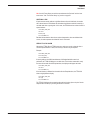
Maintenance
CLEANING THE MODULE
To clean the outside surface, use a damp cloth or sponge. Do not use solvents or abrasive
cleaners and do not open the enclosure while it is wet (it is an electrical device).
FUSE REPLACEMENT
The fuse on the power supply board of the TTDM-128 and TTSIM units is a 200-mA, 250V, quick-acting microfuse. It has an F1 rating, characteristic code F (quick-acting). Use no
other type of fuse or the TTDM could be damaged or could fail to perform properly. One
spare fuse is provided in the TTDM (see feature 15 on page 11).
ROUTINE MAINTENANCE
It is recommended that the TraceTek system be thoroughly checked twice a year. Such
a check will identify conditions that adversely affect the leak-locating capability of the
system. More frequent checks may be required if the sensing cable is repeatedly exposed
to leaks, or may be exposed to abuse due to construction or repair work. Contact your
local TraceTek representative for further information on service support.
STORAGE AND HANDLING OF SENSING CABLE
Despite their rugged construction, TraceTek sensing cables must be handled in a manner
appropriate for a sensing device or they may be damaged and require replacement.
Therefore, you should follow some basic rules for storing and handling all TraceTek
sensing cables:
§ Store spare cable in its original container in a clean, dry place until ready for
installation.
§ Schedule cable installation after all mechanical, plumbing, and electrical work has
been completed.
§ Clean the area where the cable is to be installed, and remove any obvious debris or
other sources of contamination.
§ Do not solder or weld near the cable without providing protection from heat, solder
flux, or weld splatter.
§ Do not drop tools or floor tile on the cable; sharp or heavy objects may damage the
cable.
§ Avoid walking or stepping on the cable. Provide shielding (for example, a half shell of
plastic pipe) where additional protection is necessary.
§ Do not use tape to secure sensing cable (some tapes and adhesives absorb moisture)
or use solvents that could eventually cause an alarm.
§ Do not drag sensing cable through contaminants (such as pipe dope, PVC cement,
solvents, oil, or dirt).
H56853 12/03
34
TTDM-128
User Manual
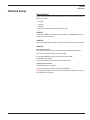
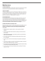
INVESTIGATING LEAKS AND FAULTS
Alarm and
locating module
If the location of a leak is not apparent, it is often useful to subdivide the leak detection
circuit. To accomplish this, it is best to have a TraceTek Portable Test Box (PTB) or
extra TTSIM, and an extra Modular End Termination. Contact your locate TraceTek
representative to obtain these products.
To subdivide the system and isolate the problems, find a connection at a convenient point
somewhere near the center of the detection circuit. You can then use a PTB or add an
additional TTSIM to test the “back half” of the sensing circuit (to verify circuit integrity,
and to detect the presence of liquid and determine its location). If you install an end
termination on the “front half” of the circuit (going back to the existing module), you can
use that module to check the “front half” of the sensing circuit.
If you add a new TTSIM to the leak detection network (by connecting it to the RS-485
wiring connected to the TTDM-128), follow the Set SIM Address instructions on page 5
then perform an Update Network command (page 26). Examine the SIM Status of the new
(“front half”) and old (“back half”) channels, and compare with the SIM Status of the former
combined sensing circuit.
End termination
You can further subdivide the circuit, and even test individual lengths of cables. Even the
most perplexing problems can usually be isolated and resolved using this methodical
approach. If you wish to remove SIMs, remember to use the Init Network menu.
TTSIM
End termination
End termination
End termination
PTB
H56853 12/03
35
Appendix 1 - Events Glossary
Type of
Event
Message
Description
Power
Power Down
The time the power was last supplied to the TTDM-128 is stored in
nonvolatile memory and is entered into the Events History log when
power is restored.
Restart
The Events History log records when power is supplied to the unit or
when the unit is manually restarted.
Leak
Liquid detected at the displayed channel and location.
Re-Alarm
Occurs under three different situations:
Leak
• Location changed past Re-Alarm threshold.
• New leak location is more than 8 m (25 ft) from the last stored
location on the channel (new average is shown in brackets).
• Automatic Re-Alarm after the Re-Alarm interval (a user setting) if
the leak condition still exists.
Fault
Service
User
Action
H56853 12/03
Leak Cleared
Displayed when channel status returns to normal after a leak is
cleared.
New Leak
A new leak on a channel is detected after an earlier leak is cleared
but before the leak relay is Reset.
Cable Break
Loss of continuity in both loops of the sensing circuit. May be
caused by broken or disconnected sensing cable, jumper cable, or
connections.
YB Loop Break
Break in the Yellow/Black loop of the sensing cable.
RG Loop Break
Break in the Red/Green loop of the sensing cable.
Loop Imbalance
Resistance of the two cable loops indicates more than 25% difference
in measured resistance. May be early indication of cable deterioration
or damage, or electrical contact of one sensing wire with a ground
(earth) path.
Cable Restored
Displayed when cable returns to normal after any fault condition.
SI Comm Error
Communications problem between TTDM-128 unit and any installed
SIM channel.
SI Comm Recovered
Displayed when communication with SIM unit is re-established.
SI H/W Error
A self-test of the SIM unit has failed. The unit needs to be repaired or
replaced.
SI H/W Recovered
Displayed after a SIM hardware problem has been corrected.
Service Required
A small amount of current is flowing between the two sensing wires
in the sensing cable. This is usually caused by a very small leak or
buildup of contaminants. The TTDM-128 may indicate a location in
brackets if it can obtain consistent measurements.
Service Clear
Displayed when the condition requiring service has been cleared (for
example, the sensing cable is clean and dry).
Settings Changed
Whenever any user-setup parameter is changed, the event is logged
in the Event History.
Alarm Silenced
User pressed the silence button.
Reset
User pressed the reset button, or the system performed an automatic
reset (if configured for Auto Reset).
36
TTDM-128
User Manual
Appendix 2 Connection to Other Devices
NOTE: All connections to external devices are made at the TTDM-128.
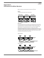
RELAYS
TTDM-128 has three relays: Service, Leak and Fault:
SERVICE RELAY
LEAK RELAY
FAULT RELAY
15 16 17 18 19 20
21 22 23 24 25 26
27 28 29 30 31 32
Relay Logic
Each relay provides two Form-C relay contacts, with normally open and normally closed
contacts both provided. The relays are de-energized to indicate an alarm condition. The
diagram below shows the relay status when each is in an alarm (de-energized) state.
Wiring Options to Gang Alarm Relays on a Single Pair of Wires
The following illustrations show how the relays can be jumpered together to allow remote
monitoring of the TTDM-128 system status with only a single pair of wires. The TTDM-128
de-energizes its relays to signal an alarm condition. Therefore, loss of power as well as
any other type of alarm would trip the remote alarm.
Open on Alarm
Relays wired
in series
15 16 17 18 19 20
21 22 23 24 25 26
27 28 29 30 31 32
Monitoring circuit
(open on alarm)
Close on Alarm
Relays wired
in parallel
15 16 17 18 19 20
21 22 23 24 25 26
27 28 29 30 31 32
Monitoring circuit
(close on alarm)
H56853 12/03
37
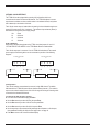
OPTIONAL 4-20 MA INTERFACE
The TTDM-128 can be equipped with an analog 4-20 mA interface which can
communicate the status of a selected SIM channel. The TTDM-128 adjusts its current
output based on whether an alarm condition exists in the selected channel, and (when a
leak is detected) on the location of the leak.
The 4-20 mA current output is isolated from the sensing circuit and therefore requires an
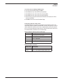
external DC power supply (26.4 V maximum). The maximum loop resistance (Rmax) is
determined according to the power supply voltage:
Vdc
24
18
12
Rmax
900 ohms
600 ohms
300 ohms
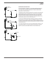
4-20 mA Wiring
Before wiring the external equipment to the TTDM, check that jumpers J11 and J12
“OPTION PCB INT PWR JMPRS” on the TTDM Mother Board are not installed.
The 4-20 mA output port is connector J2 on the TTDM-128 motherboard. The external
power supply and monitoring device can be connected as per either of the following
diagrams:
���� �� ��� ����
��
���� �� ��� ����
��
���� ���� �� �����
��
��
�� ��
���� ���� �� �����
��
��
�� ��
��� ��� ������ �
� ������� �
� ������� �
��� ��� ������ �
Configuration
The 4-20 mA interface communicates the status of a single SIM channel. The default
SIM channel is the TTDM-128 internal Sensor Interface board (channel 1). The module’s
output can be scaled to make full use of the 4-20 mA range for the length of sensing cable
connected to the selected SIM channel.
To change the leak location scaling:
► From the Current Event/Status Display, press MENU.
► Use the DOWN arrow key to select Self Test, then press ENTER.
► Use the DOWN arrow key to select 4-20 mA Test, then press ENTER.
► Use the DOWN arrow key to select 20 mA Val, then press ENTER.
► Use the arrow keys to input the desired full scale length that will equate to a 20 mA output,
then press ENTER. Normally this will be the Test Length value - see page 18.
► Press MENU to return to the Current Event/Status Display.
H56853 12/03
38
TTDM-128
User Manual
To use the port for a different SIM channel:
► From the Current Event/Status Display, press MENU.
► Use the DOWN arrow key to select Self Test, then press ENTER.
► Use the DOWN arrow key to select 4-20 mA Test, then press ENTER.
► Use the RIGHT arrow key to select 4-20 mA SIM, then press ENTER.
► Use the arrow keys to input the desired channel number that will be output by the 4-20 mA
circuit, then press ENTER.
► Press MENU to return to the Current Event/Status Display.
Interpreting 4-20 mA output values
The TTDM-128 adjusts its current loop output based on the leak detection status of the
selected SIM channel, as detailed in the table below. Outputs in the range of 0 to 4 mA are
used to indicate fault conditions (0 to 3.5 mA) or normal operation (4 mA), while outputs in
the 5 to 20 mA range indicate the location of a leak. The leak location values output by the
4-20 mA board have a resolution of 0.5% of the scale range.
Fault conditions coded into the 0-4 mA range:
Output (mA)
Description
0
Electronics fault or loss of power
1.0
Fault — SIM communications
2.0
Fault — cable break
3.0
Fault — cable damage
3.5
Service Required alarm (loop imbalance)
Normal condition and leaks:
H56853 12/03
Output (mA)
Description
4.0
System normal
5.0–20.0
Leak — value scaled to indicate location of leak
39
TTDM-128
TraceTek Leak Detection
�
Master Module
For more information see:
www.tracetek.com
www.tycothermal.com
Worldwide Headquarters
Tyco Thermal Controls
300 Constitution Dr.
Menlo Park, CA 94025-1164
USA
Tel (800) 545-6258
Fax (800) 596-5004
Europe
Tyco Thermal Controls
Staatsbaan 4A
3210 Lubbeek
Belgium
Tel +32 (16) 213-511
Fax +32 (16) 213-600
Asia
Tyco Thermal Controls
9th Floor, Yeul-Chon Building
24-1, Yeoido-Dong
YeungDeungpo-ku
150-010 Seoul, South Korea
Tel +82 (2) 2129-7731
Fax +82 (2) 785-4700
[email protected]
www.tycothermal.com
Important: All information, including illustrations, is believed to be reliable. Users, however, should independently evaluate the suitability of each product for their
particular application. Tyco Thermal Controls makes no warranty as to the accuracy or completeness of the information, and disclaims any liability regarding its
use. Tyco Thermal Controls’ only obligations are those in the Tyco Thermal Controls Standard Terms and Conditions of Sale for this product, and in no case will
Tyco Thermal Controls or its distributors be liable for any incidental, indirect, or consequential damages arising from the sale, resale, use or misuse of the product.
Specifications are subject to change without notice. In addition, Tyco Thermal Controls reserves the right to make changes – without notification to Buyer – to
processing or materials that do not affect compliance with any applicable specification.
Tyco, TraceTek and the TraceTek logo are trademarks of Tyco Thermal Controls LLC or its affiliates.
MODBUS is a trademark of Gould, Inc. OptoMux is a trademark of Opto-22. Metasys is a trademark of Johnson Controls.
©2003 Tyco Thermal Controls LLC H56853 12/03
Or contact us at one of these locations: