1
SMDC-16
PROGRAMMING MANUAL
SMDC-16 Digital Control Communicator
and
SMPC-32 Personal Control
Optex Inc. - 1845 W 205th St. - Torrance, Ca. 90501 - 800-966-7839
SMDC-16 Program Manual
3440-0252 A4
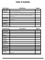
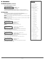
Table of Contents
Main Menu
Sub Menus
Page #
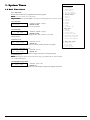
1. System Times
1.1. Delay Times - 1.2. Cutoff Times - 1.3. Self Test - 1.4 Time Clock
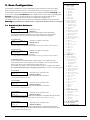
2. Zone
Configuration
2.1. Zone Config. - 2.2. Templates - 2.3. Cross Zones - 2.4. # Shunt Alms - 2.5. Shunt
Period - 2.6. # of Exp Bds. 2.7. Wireless
10 - 20
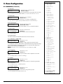
3. Receiver
3.1. Receiver - 3.2. # Telco Lines - 3.3. Monitor Options - 3.4. # Dial Attempts - 3.5. Dial
Features - 3.6. Comm Fail Code - 3.7. TLM Options - 3.8. Rcvr Options - 3.9. Radio Options
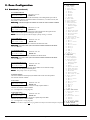
4.1. Monitor Mode - 4.2. Walk Test - 4.3. System features - 4.4. System Messages - 4.5.
Emergency 4.6. Two Wire Smokes - 4.7. Force Arming - 4.8. PGM / INP Functions 4.9. Temporal Fire
5.1 . Report Menu 1 - 5.2. Report Menu 2 - 5.3. Report Menu 3
21 - 27
44 - 46
8. Schedules
6.1. Installer PIN - 6.2. Duress PIN - 6.3. Special PIN - 6.4. Open/Close Report Codes 6.5 Review PIN 1
7.1. Telephone # - 7.2. # of Rings - 7.3. Caller ID - 7.4. - Download PIN - 7.5. Panel Access
ID
8.1. Types - 8.2. Window System - 8.3. Auto Arm
9. Partitions
9.1. Types - 9.2. Zone Partition - 9.3. Keypad Assignment - 9.4. User Assignment
54 - 56
0.
Pager/Fax/Printer
0.1. Pager Options 0.2 Fax Options - 0.3 Printer Options
57 - 58
4. System Options
5. Report Codes
6. PIN Numbers
7. Downloader
Program Info
6-9
Description
28 - 37
38 - 43
47
48 - 53
Page #
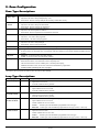
Alphabet
Quick reference chart
19
Contact ID Info
Quick reference chart - additional report code options
42
Dictionary
Quick reference chart
19
Hexadecimal
Chart
Quick reference chart
42
INP Options
Quick reference chart
37
Introduction
Introduction to programming
3
Loop Type
Description
Quick reference chart
20
Monitor
Information
Quick reference chart - Functional information
29
Output Options
Quick reference chart
43
PGM Output
Options
Quick reference chart
37
Program Map
Flow chart
4-5
Receiver Routing
Quick reference chart
27
Receiver Types
Quick reference chart
27
Report Codes
Quick Reference chart of program locations and receiver routing
27
SIA Information
Quick reference chart - additional report code options
43
Zone Type
Description
Quick reference chart
20
UL Addendum
UL information
59
Optex Inc. - 1845 W 205th St. - Torrance, Ca. 90501 - 800-966-7839
SMDC-16 Program Manual
3440-0252 A4
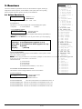
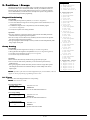
Introduction & Program Hints
All programming for the OPTEX INC. SMDC may be accomplished through the SMPC-32 Personal Control Keypad or from the DOS –
SRPU Download Software. English language prompts guide the programmer through easy to follow menu options should you choose to
program via the SMPC keypads.
• Should your company wish to receive a copy of the SRPU software, please contact Tech Support at Optex Inc.- 800-966-7839.
Programming the OPTEX INC. SMDC
•
•
•
•
•
Installer Programming for the OPTEX INC. SMDC is made up of ten main menus, each containing various sub-menus that are
arranged by system functions to simplify the programming procedure. (See page 3 & 4 for an expanded view of the menu options).
To access the OPTEX INC. SMDC Installer Program, press 0000 + PROGRAM, the LCD will change to ‘ENTER YOUR
COMPANY PIN’. At this time enter the factory installed code of 9999.
Once the factory installed code has been entered, the top line of the LCD will display ‘ENTER RESPONSE’ and the bottom line of
the LCD will be scrolling the nine (9) main menus beginning with “1 SYSTEM TIMES,” “2 ZONE CONFIG,” and so on. To select
one of the nine main menu options, simply press the number that corresponds to the desired menu.
Once inside one of these menus, the top line will display the name of the menu you are currently in and the bottom line will again
scroll the available options. To exit out of a given menu, press the CLEAR key. This will take you back to the previous menu option
each time the CLEAR key is pressed.
To exit out of the Installer Program, press the CLEAR key when the top line is displaying “Enter Response.”
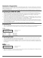
Programming Tip
•
Next to each programming description in this manual you will notice that there are numbers next to each programming option. This
number is a quick reference as to which numbers to press at the keypad to access that programming memory location.
Example:
1.1.5. A C Fail Display
AC Fail Display
NO 0=NO 1=YES
The first 1.
The second 1.
The 5.
denotes
denotes
denotes
Selections: Yes / No
Default: No
“System Times”
“Delay Times”
“AC Fail Display”
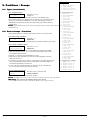
Programming Prompts
•
•
Each of the programming prompts contained in the Installer Program are explained in detail, indicates what the factory default
values are and the possible range of entries that can be programmed.
Throughout the program, you will be prompted for either YES or NO type questions that must be responded to by either pressing
the 0 key followed by the ENTER key to disable the option or to press the 1 key followed by the ENTER key to enable this option.
(See Example 2)
Example: 2
2.1.2. Telephone Output
Z-1
YES
•
TELEPHONE
0=NO 1=YES
Selections: Yes / No
Default: No
Other menus will prompt you for an entry, that after you have made your selection, will be pulsating on the LCD display which you
must press the ENTER key to lock in your selection to memory.
Optex Inc. - 1845 W 205th St. - Torrance, Ca. 90501 - 800-966-7839
SMDC-16 Program Manual
3440-0252 A4
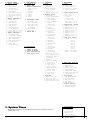
Installer Program Menu
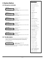
1. System Times
1. Delay Times
1. Pre-Alarm Delay
2. Entry Delay
3. Exit Delay
4. AC Fail Delay
5. AC Fail Display
2. Cutoff Times
1. Bell 1
2. Bell 2
3. Relay 1
4. Relay 2
5. PGM 1
6. PGM 2
7. PGM 3
8. Listen-In
3. Self Test
1. Daily
2. Weekly
3. Time of Day
4. Self Test Code
5. Abnormal Test Code
6. Telco Test Report
7. Radio Test Report
4. Real Time Clock
1. Time Clock
1. Set Date
2. Set Time
2. Set by User
3. Display for User
4. Daylight Saving
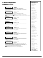
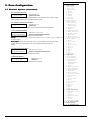
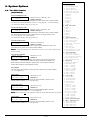
2. Zone Configuration
1. Zone Configure
(Set Zone Number)
pre-defined YES/NO
1. Zone Type
2. Loop Type
3. Report Codes
1. Alarm
2. Trouble
3. Bypass
4. Cancel
5. Restore
4. Zone Name
5. Loop Response
6. Entry Delay
7. Zone Features
1. Silent Day/
Audible Night
2. Telephone
3. Radio
4. Bypass Allowed
5. Shunt Allowed
6. Display Armed
7. Walk Test
8. Monitor Mode
9. Auto Walk at Arm
8. Zone Outputs
1. Bell 1
2. Bell 1 Pulse
3. Bell 2
4. Bell 2 Pulse
5. Relay 1
6. Relay 2
7. PGM 1
8. PGM 2
9. PGM 3
9. Alarm Verify
2. Templates
(Set Zone Type)
1. Loop Response
2. Zone Features
1. Silent Day/
Audible Night
2. Telephone
3. Radio
4. Bypass Allowed
5. Shunt Allowed
6. Display Armed
7. Walk Test
8. Monitor Mode
9. Auto Walk at Arm
3. Zone Outputs
1. Bell 1
2. Bell 1 Pulse
3. Bell 2
4. Bell 2 Pulse
5. Relay 1
6. Relay 2
7. PGM 1
8. PGM 2
9. PGM 3
3. Cross Zoning
1. Cross Pair 1
2. Cross Pair 2
3. Cross Zone Timer
4. Number of Shunt Alm
5. Shunt Period
Optex Inc. - 1845 W 205th St. - Torrance, Ca. 90501 - 800-966-7839
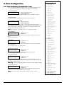
3. Receivers
1. Select Receiver #
1. Receiver 1
1. Telephone #
2. Account Numbers
1 Account # 1-40
1. Zones 1-8
2. Zones 9-16
3. Zones 17-24
4. Zones 25-32
5. Zones 33-40
2. Account # 41-80
1. Zones 41-48
2. Zones 49-56
3. Zones 57-64
4. Zones 65-72
5. Zones 73-80
3. Part Acct #’s
1. Part 1
2. Part 2
3. Part 3
4. Part 4
5. Part 5
6. Part 6
7. Part 7
8. Part 8
4. Common Acct. #
3. Format
2. Receiver 2
1. Telephone #
2. Account #’s
1 Account # 1-40
2 Account # 41-80
(Same as Rcvr 1)
3. Part Account #’s
(Same as Rcvr 1)
4. Common Acct. #
3. Formats
2. # of Telco Lines
3. Tel. Monitor Options
1. Monitor Both Lines
2. Keypad Audible
3. Bell 1 Output
4. Bell 2 Output
5. Relay 1 Output
6. Relay 2 Output
7. PGM 1 Output
8. PGM 2 Output
9. PGM 3 Output
4. Number of Dial Atts.
5. Dial Features
1. TouchTone/Rotary
2. Fallback on Rotary
3. Delay Before Dial
4. TLM fault time
5. Anti-Jam Time
6. Comm Fail Rpt Code
7. TLM Report Codes
1. TLM Fault
2. TLM Restore
8. Rcvr Report Options
1. Alarms
2. Open/Close
3. System
4. Partition #
1. Partition 1
2. Partition 2
SMDC-16 Program Manual
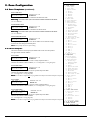
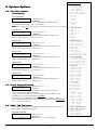
4. System Options
1. Monitor Mode
1. Ack Required
2. Scroll Open Zones
3. Scroll Bypass
4. Silent Monitor Mode
5. Auto Monitor on
Disarm
6. PIN Entry Required
7. Monitor Mode Outputs
1. Bell 1 Output
2. Bell 2 Output
3. Relay 1 Output
4. Relay 2 Output
5. PGM 1 Output
6. PGM 2 Output
7. PGM 3 Output
2. Walk Test Mode
1. Bell 1 Output
2. Bell 2 Output
3. Relay 1 Output
4. Relay 2 Output
5. PGM 1 Output
6. PGM 2 Output
7. PGM 3 Output
3. System Features
1. Hist. View by User
2. O/C View by User
3. Silent Trouble
4. Not Used - Reserved
5. 50Hz/60Hz
6. AC/Crystal
7. Pwr Dly Time
before Zone Process
8. PIN Entry Required
for Zone Scan
9. Thresh of Bad Codes
4. System Messages
1. Top Line Display
1. Group/Part 1 Display
2. Group/Part 2 Display
3. Group/Part 3 Display
4. Group/Part 4 Display
5. Group/Part 5 Display
6. Group/Part 6 Display
7. Group/Part 7 Display
8. Group/Part 8 Display
2. Disarmed Nml Msg
3. Disarmed Abnnml Msg
5. Emergency
1. Emergency Enabled
2. Emergency Rpt
3. Bell Output 1
4. Bell Output 2
5. Relay Output 1
6. Relay Output 2
7. PGM Output 1
8. PGM Output 2
9. PGM Output 3
6. 2 Wire Smoke Loop
1. Alarm Report
2. Trouble Report
3. Smoke Restore
4. Smoke Reset Time
5. Alarm Verify.
6. Outputs
1. Bell 1 Output
3440-0252 A4
6. Number of Exp. Bds
7. Wireless
1. System ID
2. WX Super Time
3. # of WX Xmtrs
4. Xmtrs Enabled
5. Supervised Xmtrs
6. Disable Remote
3. Partition 3
4. Partition 4
5. Partition 5
6. Partition 6
7. Partition 7
8. Partition 8
9. Radio Options
1. Radio attempts
2. Radio first
3. Radio account
2. Pulse Bell 1
3. Bell 2 Output
4. Pulse Bell 2
5. Relay 1 Output
6. Relay 2 Output
7. PGM 1 Output
8. PGM 2 Output
9. PGM 3 Output
7. Force Arming Enabled
8. PGM / INP Functions
9. Temporal Fire
Installer ProgramMenu
Optex Inc. - 1845 W 205th St. - Torrance, Ca. 90501 - 800-966-7839
SMDC-16 Program Manual
3440-0252 A4
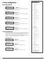
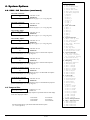
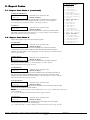
5. Report Codes
1. Report Code Menu 1
1. AC Fail
2. AC Restore
3. Low Battery
4. Battery Restore
5. Box Tamper
6. Box Tamper Restore
7. Bell Fault Trouble
8. Bell Fault Restore
9. Duress
2. Report Code Menu 2
1. Bus Fault
2. Bus Restore
3. Bell Restore
4. Open Restore
5. Exit Error
6. Open Exception
7. Close Exception
8. Enter Install. Prog
9. Exit Install. Prog.
3. Report Code Menu 3
1. O/C Buffer Full
2. O/C Buffer Overflow
3. Unauthorized User
4. Aux. Power Fail
5. Aux. Power Restore
6. Ground Fault
7. Force Arm
8. On Premise Arm
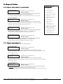
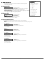
6. PIN Numbers
8. Schedules
1. Installer PIN
2. Duress PIN
3. Special PIN Feature
1. Special PIN #
2. Outputs
1. Relay 1
2. Relay 2
3. PGM 1
4. PGM 2
5. PGM 3
4. User Report Codes
1. All Open Code
2. All Close Code
3. User Open Code
4. User Close Code
5. PC Ringback
6. Bell Ringback
7. Bell Test
5. Review PIN 1
7. Downloader
1.
2.
3.
4.
5.
Phone Number
Number of Rings
Caller ID Enable
Local Download PIN
Panel Access ID #
1. Types
1. Schedule 1
2. Schedule 2
3. Close w/Bypass
4. Close w/Alarm
5. User Set
6. Report Open/Close
2. Windows System
1. Schedule 1
1. Open/Close Window
1. Open Window
2. Close Window
2. Group Schedule 1.
1. Sunday
1. Open Time
2. Close Time
2. Monday
1. Open Time
2. Close Time
3. Tuesday
1. Open Time
2. Close Time
4. Wednesday
1. Open Time
2. Close Time
5. Thursday
1. Open Time
2. Close Time
6. Friday
1. Open Time
2. Close Time
7. Saturday
1. Open Time
2. Close Time
(Sched. for Grps 28 is prgmd the same).
2. Schedule 2 (same
as Schedule 1).
3. Holidays
4. Temporary Sched. 1
1. Select Group #
1. Select Date
2. Open Start
3. Close Start
5. Temporary Sched. 2
1. Select Group #
1. Select Date
2. Open Start
3. Close Start
3. Auto Arm
1. Enable Auto Arm
2. Auto Arm Code
3. Fail Auto Arm Code
4. Preclose Warn. Tone
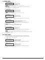
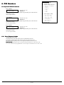
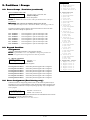
1. System Times
The information in Section 1 has four sub menus: Delay Times, Cutoff Times, Self Test,
and Real Time Clock.
Optex Inc. - 1845 W 205th St. - Torrance, Ca. 90501 - 800-966-7839
SMDC-16 Program Manual
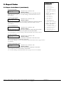
9. Partitions
1. Types
1. Keypad Partition
2. Group Arming
3. Total # of Groups
4. Common Group #
2. Zones Grp/Partition
(Select Part #)
1. Partition 1
1. Zones
2. Open Code
3. Close Code
(Prog Part. 2-8 in
same manner as 1)
3. Keypad Part. Assign.
1. Keypad 1 Part. #
2. Keypad 2 Part. #
3. Keypad 3 Part. #
4. Keypad 4 Part. #
5. Keypad 5 Part. #
6. Keypad 6 Part. #
7. Keypad 7 Part. #
8. Keypad 8 Part. #
4. User Part. Assign.
User# 1 Part 1
Part 2
Part 3
Part 4
Part 5
Part 6
Part 7
Part 8
User# 2- 99 same as
User# 1 assignment
0. Pager/Fax Printer
1. Pager Options
1. Pager Tel 1
2. Pager Tel 2
2. Pager Delay Time
3. Alarm Report
4. Open/Close Report
5. Open/Close Fail Rpt
6. System Report
2. Fax Options
1. Fax Phone Number
2. Modem Command
3. Fax Class 2.0
4. Fax Time
5. Fax Schedule
3. Printer Options
1. Printer Enabled
2. Logging Option
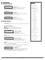
1. System Times
1. Delay Times
1. Pre-Alarm
2. Entry Delay
3. Exit Delay
4. AC Fail Delay
5. AC A4
Fail Display
3440-0252
2. Cutoff Times
1.1 Delay Times
1.1.1 Pre-Alarm Delay
PREALARM DELAY
Selections: 0-255 sec.
00 SECONDS
Default: 0 seconds .
Select the amount of time for silent entry delay.
N o t e : This value of time will add on to the total entry delay time.
E x a m p l e : 15 sec. Pre Alarm Delay + 15 sec. Entry Delay = 30 sec. Ttl Entry Delay
(see 1.1.2-Entry Delay / 2.1.6-Zone Entry Delay).
1.1.2 Entry Delay
ENTRY Delay
Selections: 0-255 sec.
00 SECONDS
Default: 45 seconds
Select the required entry delay.
N o t e : (see 2.1.6-Entry Delay to customize the entry time by zone).
1.1.3 Exit Delay
EXIT DELAY
Selections: 0-255 sec.
00 SECONDS
Default: 60 seconds.
Select the required exit delay time.
N o t e : This exit delay is common to all exit zones and cannot be customized by zone.
1.1.4 AC Fail Delay
AC FAIL DELAY
Selections: 0-99 x 10 Minutes.(16.5 hrs. max)
00 x 10 MINUTES
Default: 360 minutes (6 hrs)
Select the amount of time the panel will wait before transmitting the AC Fail Report code
to the central station.
N o t e : This delay is for communications only, not display.
(see 1.1.5-AC Fail Display / 5.1.1-AC Fail Report Code).
1.1.5 AC Fail Display
AC Fail Display
Selections: Yes / No
YES 0=NO 1=YES
Default: Yes
Enable this option to allow the SMDC to display audibly and visually the AC Fail message
at all keypads.
N o t e : A PIN is required to be entered to silence this warning indicator.
N o t e : The AC Fail Display message will occur at all keypads approximately 10 seconds after
the AC fault has occurred.
1.2 Cutoff Times
Cutoff times allow for the customizing of the trigger outputs. These outputs maybe used
for a variety of purposes. (see 2-Zone Config. / 3.3-Tel. Monitor / 4.5-Emergency/Duress
/ 4.6-Two Wire Smokes / Wiring diagram).
1.2.1 Bell 1 Cutoff
BELL 1 CUTOFF
Selections: 0-99 minutes.
10 MINUTES
Default: 10 minutes
Select the amount of time in minutes alarm output voltage will be present for Bell 1 output.
1.2.2 Bell 2 Cutoff
BELL 2 CUTOFF
Selections: 0-99 minutes.
10 MINUTES
Default: 10 minutes.
Select the amount of time in minutes alarm output voltage will be present for Bell 2 output.
Optex Inc. - 1845 W 205th St. - Torrance, Ca. 90501 - 800-966-7839
SMDC-16 Program Manual
3440-0252 A4
1. System Times
1 . 2 C u t o f f T i m e s (continued)
1.2.3 Relay 1 Cutoff
RELAY 1 CUTOFF
Selections: 0-99 minutes.
10 MINUTES
Default: 10 minutes.
Select the amount of time in minutes Relay 1 will remain energized.
1.2.4 Relay 2 Cutoff
RELAY 2 CUTOFF
Selections: 00-99 minutes.
10 MINUTES
Default: 10 minutes.
Select the amount of time in minutes Relay 2 will remain energized.
1.2.5 PGM 1 Cutoff
PGM 1 CUTOFF
10 MINUTES
Selections: 00-99 minutes.
Default: 10 minutes.
Select the amount of time in minutes PGM 1 will remain energized.
1.2.6 PGM 2 Cutoff
PGM 2 CUTOFF
Selections: 00-99 minutes
10 MINUTES
Default: 10 minutes
Select the amount of time in minutes PGM 2 will remain energized.
1.2.7 PGM 3 Cutoff
PGM 3 CUTOFF
Selections: 00-99 minutes
10 MINUTES
Default: 10 minutes
Select the amount of time in minutes PGM 3 will remain energized.
1. System Times
1. Delay Times
1. Pre-Alarm
2. Entry Delay
3. Exit Delay
4. AC Fail Delay
5. AC Fail Display
2. Cutoff Times
1. Bell 1
2. Bell 2
3. Relay 1
4. Relay 2
5. PGM 1
6. PGM 2
7. PGM 3
8. Listen - In
3. Self Test
1. Daily
2. Weekly
3. Time of Day
4. Self Test Code
5. Abnormal test Code
6. Telco Test Report
7. Radio Test Report
4. Real Time Clock
1. Time Clock
1. Set Date
2. Set Time
2. Set by User
1.2.8 Listen-In Cutoff
LISTEN IN CUTOFF
Selections: 00-99 minutes
00 MINUTES
Default: 00 minutes
Select the amount of time in minutes Listen-In will remain energized.
(additional equip. required).
1.3 Self Test
Self Test reports can be used to periodically test the integrity of the communication link
between the SMDC and the central station. Test reports may be sent on a daily
or weekly basis.
1.3.1 Daily Self Test
DAILY TEST RPT
Selections: Yes / No
NO 0=NO 1=YES
Default: No
Enable this option for the SMDC to transmit a self test report on a daily basis.
(see 1.3.4-Test Rpt Code / 1.3.5-Ab Test Rpt Code / 3.8.3-Rcvr Routing)
1.3.2 Weekly Self Test
WEEKLY TEST RPT
Selections: Yes / No
NO 0=NO 1=YES
Default: No
Enable this option for the SMDC to transmit a self test report on a weekly basis.
1.3.2 Day of Week
DAY OF WEEK
0
Selections: 1-7
NO 0=NO 1=YES
Default: 0
Select the day of the week for transmission of the self test code after weekly test has been enabled.
(see 1.3.4-Test Rpt Code / 1.3.5-Ab Test Rpt Code / 3.8.3-Rcvr Routing).
Optex Inc. - 1845 W 205th St. - Torrance, Ca. 90501 - 800-966-7839
SMDC-16 Program Manual
3440-0252 A4
1. System Times
1.3 Self Test (continued)
1.3.3 Time of Day for Self Test
TIME HH:MM
Selections: 12:00am - 11:59pm
__:__ AM 1=PM
Default: No time
Select the time of day the Self Test report will be transmitted to the central station.
(see 1.3.4-Test Rpt Code / 1.3.5-Ab Test Rpt Code / 1.3.6-Telco / 3.8.3-Rcvr Routing).
1.3.4 Self Test Code
SELF TEST CODE
Selections: 01-FF / Contact ID / SIA
code NO
Default: No report
Select the Self Test report code that will be transmitted to the central station via
both digital and radio (requires additional radio hardware).
(see SIA-Contact ID-Hex charts on pg 42 & 43).
1.3.5 Abnormal Test Code
ABNORMAL CODE
Selections: 01-FF / Contact ID / SIA
code NO
Default: No Report
Select the Abnormal Code that will be transmitted to the central station when a zone(s)
designated as a Fire Zone and/or the 2-wire smoke detector zone has gone into an alarm
condition that has not been restored to a normal condition once the Self Test Time arrives.
(see SIA-Contact ID-Hex charts on pg 42 & 43).
1.3.6 Report Self Test on Telco
TELCO REPORT
Selections: Yes / No
YES 0=NO 1=YES
Default: Yes
Enable this option to transmit the Self Test report code via the telephone line(s).
1. System Times
1. Delay Times
1. Pre-Alarm
2. Entry Delay
3. Exit Delay
4. AC Fail Delay
5. AC Fail Display
2. Cutoff Times
1. Bell 1
2. Bell 2
3. Relay 1
4. Relay 2
5. PGM 1
6. PGM 2
7. PGM 3
8. Listen - In
3. Self Test
1. Daily
2. Weekly
3. Time of Day
4. Self Test Code
5. Abnormal test Code
6. Telco Test Report
7. Radio Test Report
4. Real Time Clock
1. Time Clock
1. Set Date
2. Set Time
2. Set by User
1.3.7 Report Self Test on Radio
RADIO REPORT
Selections: Yes / No
NO 0=NO 1=YES
Default: No
Enable this option to transmit the Self Test report code via Varitech long range radio.
(additional hardware required).
Optex Inc. - 1845 W 205th St. - Torrance, Ca. 90501 - 800-966-7839
SMDC-16 Program Manual
3440-0252 A4
1. System Times
1.4
1. System Times
1. Delay Times
1. Pre-Alarm
Real Time Clock
2. Entry Delay
3. Exit Delay
4. AC Fail Delay
1.4.1. Time Clock
5. AC Fail Display
Both the time and date may be programmed in the installer program.
2. Cutoff Times
N o t e see 4.3.6- Clock / 4.3.6-AC Clock).
1. Bell 1
I m p o r t a n t : The Time/Date must be entered for all timing functions to operate correctly. 2. Bell 2
3. Relay 1
4. Relay 2
1.4.1.1 Set Date
5. PGM 1
DATE
Selections: 12:00am - 11:59pm
6. PGM 2
00/00/00
Default: No date
7. PGM 3
Enter the current date. (The SMDC is Y2K compliant).
8. Listen - In
3. Self Test
1. Daily
1.4.1.2 Set Time
2. Weekly
TIME HH:MM
Selections: 12:00am - 11:59pm
3. Time of Day
__:__ AM 1=PM
Default: No time
4. Self Test Code
Enter the current time. If the time being entered is “PM,” press the “1” key after
5. Abnormal test Code
entering the time.
6. Telco Test Report
7. Radio Test Report
1.4.2 Set by User
SET BY USER
Selections: Yes / No
NO 0=NO 1=YES
Default: Yes
Enable this option to allow for the user to set the date and time from the user program.
4. Real Time Clock
1. Time Clock
1. Set Date
2. Set Time
2. Set by User
1.4.3 Display Time/Date for User
DISPLAY FOR USER
Selections: Yes / No
NO 0=NO 1=YES
Default: Yes
This option will enable the date and time to display on the top line of all keypads during
the disarmed period.
N o t e : Enabling this option will override the messages programmed for the System Prompts
(see 4.4-System Messages).
1.4.4 Daylight Savings Adjust
DAYLIGHT TIME
Selections: 0=No 1=Yes
NO 0=NO 1=YES
Default: No
Enable this option to allow the internal clock to automatically compensate for daylight savings time.
Optex Inc. - 1845 W 205th St. - Torrance, Ca. 90501 - 800-966-7839
SMDC-16 Program Manual
3440-0252 A4
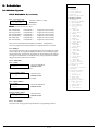
2. Zone Configuration
(Set Zone #)
1. Zone Config.
1. Zone Type
2. Loop Type
The information contained in this section will determine how each of the zones connected to the alarm
3. Report Codes
panel will respond, what report codes are to be transmitted and if cross zoning will be a factor. There
1. Alarm
are two methods a zone may be programmed. Zones may be programmed individually (Standard) or by
2. Trouble
the use of Zone Templates (Pre-Defined). Zone Templates should be used to reduce programming time.
3. Bypass
4. Cancel
Example, If there are 25 Perimeter Instant zones connected to the system that share the same
5. Restore
characteristics, programming a Perimeter Instant zone template and then applying that
4. Zone Name
zone template to each zone saves you from answering 19 additional programming prompts for each zone.
5. Loop Response
W a r n i n g : Programming Zone Templates must be completed first should you decide to use templates. 6. Entry Delay
7. Zone Features
1. Silent Day/
2.1 Standard (Pre-Defined =
Audible Night
2. Telephone
No)
3. Radio
PRE-DEFINED ?
Selections: Yes / No
4. Bypass Allowed
NO
Default: No
5. Shunt Allowed
This option determines if the zone being programmed will have all the characteristics
6. Display Armed
programmed individually (Pre-Defined = No) or if you choose to use a Zone Template
7. Walk Test
(Pre-Defined = Yes). Go to menu 2.2 should you wish to select Zone Templates.
8. Monitor Mode
9. Auto Walk at Arm
8. Zone Outputs
2.1.1 Zone Type
1. Bell 1
Z-##
TYPE 2
Selections: See Table 1: Zone Types
2. Bell 1 Pulse
(SCROLLING)
Default: Type 2
3. Bell 2
Select the appropriate Zone Type as required.
4. Bell 2 Pulse
(see page 20 for a description of the available Zone Types and their characteristics).
5. Relay 1
6. Relay 2
7. PGM 1
2.1.2 Loop Type
8. PGM 2
Z-##
TYPE 3
Selections: See Table 2: Loop Types
9. PGM 3
(SCROLLING)
Default: Type 3
9. Alarm Verify
Select the appropriate Loop Type as required.
2. Templates
(see page 20 for a description of the available Loop Types and their characteristics).
(Set Zone Type)
1. Loop Response
2.1.3 Report Codes
2. Zone Features
1. Silent Day/
Zones are capable of transmitting Alarm, Trouble, Bypass, Cancel, and Restore report
Audible Night
codes. Select the report codes as required or if for an example, you do not wish to transmit
2. Telephone
Restore codes, do not even go to that memory location, skip over it.
3. Radio
If you intend to use Ademco Contact ID or SIA format, any entry is acceptable other than 00.
4. Bypass Allowed
(See Contact ID-SIA-Hex report code options on page 42 & 43 / 3.8 Receiver Routing Option).
5. Shunt Allowed
6. Display Armed
2.1.3.1 Alarm
7. Walk Test
ALARM CODE
8. Monitor Mode
Selections: 01-FF / Contact ID / SIA
9. Auto Walk at Arm
CODE NO
Default: No Report
3. Zone Outputs
Select the alarm report code that will be transmitted to the central station.
1. Bell 1
(see Contact ID / SIA note in 2.1.3).
2. Bell 1 Pulse
3. Bell 2
2.1.3.2 Trouble
4. Bell 2 Pulse
TROUBLE CODE
Selections: 01-FF / Contact ID / SIA
5. Relay 1
CODE NO
6. Relay 2
Default: No Report
7. PGM 1
Select the trouble report code that will be transmitted to the central station.
8. PGM 2
(see Contact ID / SIA note in 2.1.3).
9. PGM 3
3. Cross Zone Pairs
2.1.3.3 Bypass
1. Cross Zone Pair 1
BYPASS CODE
Selections: 01-FF / Contact ID / SIA
1. Zone A
CODE NO
2. Zone B
Default: No Report
2. Cross Zone Pair 2
Select the bypass report code that will be transmitted to the central station after the exit delay
1. Zone A
has expired and the SMDC has been armed. (see Contact ID / SIA note in 2.1.3).
2. Zone B
3. Cross Zone Timer
2.1.3.4 Cancel
4. # of Shunt Alarms
CANCEL CODE
Selections: 01-FF / Contact ID / SIA
5. Shunt Period
CODE NO
6. # of Expander Bds.
Default: No Report
2. Zone Configuration
Select the Cancel report code that will be transmitted to the central station after an alarm
condition occurs and the system has been disarmed within two minutes of the alarm activation.
(see Contact ID / SIA note in 2.1.3).
Optex Inc. - 1845 W 205th St. - Torrance, Ca. 90501 - 800-966-7839
SMDC-16 Program Manual
3440-0252 A4
2. Zone Configuration
2 . 1 S t a n d a r d (continued)
2.1.3.5 Restore
RESTORE CODE
Selections: 01-FF / Contact ID / SIA
CODE NO
Default: No Report
Select the restore report code that will be transmitted to the central station after zone alarm
or zone trouble has reset to a normal condition. (see Contact ID / SIA note in 2.1.3).
2.1.4 Zone Name
Z-## ZONE NAME
Selections: Up to 16 characters
ZONE #
Default: Zone #
Enter the appropriate name for each zone up to 16 characters including spaces.
(see page 19 for the alphabet, list of available characters and word library).
2.1.5 Loop Response
Z-## LOOP RESP
Selections: 0001-9999 x 50 ms
0005 X 50ms
Default: 0005 x 50 ms
Enter the amount of time necessary for the SMDC to react to an abnormal condition.
2.1.6 Entry Delay
Z-## ENTRY DELAY
Selections: 00-255 Seconds
45 SECONDS
Default: 45
Select the amount of entry delay time that will be custom to this entry zone.
(see 1.2-Entry Delay).
2.1.7 Zone Features
This section determines the individual characteristics each zone will have.
2.1.7.1 Silent Day / Audible Night
Z## SILENT DAY
Selections: Yes / No
NO 0=NO 1=YES
Default: No
The SMDC will not energized either bell 1 or bell 2 outputs when the alarm system
is in a disarmed condition if enabled. However the PGMs and the relay outputs will change
state if programmed as an alarm output. The SMDC will activate the bell outputs when
this zone is activated during an armed period,
N o t e : This option is to be used with 24 hour, Fire and Day zones only.
2.1.7.2 Telephone
Z## TELEPHONE
Selections: Yes / No
YES 0=NO 1=YES
Default: Yes
Enable this option to allow all zone report to transmit codes via telephone to the central
station.
(see 2.1.3-Report Codes / 3.8-Receiver Routing).
2.1.7.3 Radio
Z## RADIO
Selections: Yes / No
NO 0=NO 1=YES
Default: No
Enable this option to allow all zone report codes to transmit via Varitech long range radio
to the central station.
(See 2.1.3-Report Codes / 3.9-Radio Options).
2.1.7.4 Bypass Allowed
Z## BYPASS
Selections: Yes / No
YES 0=NO 1=YES
Default: Yes
This option determines if this zone will be able to be bypassed by the user.
(see user manual for PIN authorization levels).
Optex Inc. - 1845 W 205th St. - Torrance, Ca. 90501 - 800-966-7839
SMDC-16 Program Manual
2. Zone Configuration
(Set Zone #)
1. Zone Config.
1. Zone Type
2. Loop Type
3. Report Codes
1. Alarm
2. Trouble
3. Bypass
4. Cancel
5. Restore
4. Zone Name
5. Loop Response
6. Entry Delay
7. Zone Features
1. Silent Day/
Audible Night
2. Telephone
3. Radio
4. Bypass Allowed
5. Shunt Allowed
6. Display Armed
7. Walk Test
8. Monitor Mode
9. Auto Walk at Arm
8. Zone Outputs
1. Bell 1
2. Bell 1 Pulse
3. Bell 2
4. Bell 2 Pulse
5. Relay 1
6. Relay 2
7. PGM 1
8. PGM 2
9. PGM 3
9. Alarm Verify
2. Templates
(Set Zone Type)
1. Loop Response
2. Zone Features
1. Silent Day/
Audible Night
2. Telephone
3. Radio
4. Bypass Allowed
5. Shunt Allowed
6. Display Armed
7. Walk Test
8. Monitor Mode
9. Auto Walk at Arm
3. Zone Outputs
1. Bell 1
2. Bell 1 Pulse
3. Bell 2
4. Bell 2 Pulse
5. Relay 1
6. Relay 2
7. PGM 1
8. PGM 2
9. PGM 3
3. Cross Zone Pairs
1. Cross Zone Pair 1
1. Zone A
2. Zone B
2. Cross Zone Pair 2
1. Zone A
2. Zone B
3. Cross Zone Timer
4. # of Shunt Alarms
5. Shunt Period
6. # of Expander Bds.
3440-0252 A4
2. Zone Configuration
(Set Zone #)
1. Zone Config.
1. Zone Type
2. Loop Type
S t a n d a r d (continued)
3. Report Codes
1. Alarm
2.1.7.5 Shunt Allowed
2. Trouble
Z## SHUNT
Selections: Yes / No
3. Bypass
NO 0=NO 1=YES
4. Cancel
Default: No
5. Restore
This option determines if this zone will automatically cease sending alarm report codes to
4. Zone Name
the central station after the programmed number of activation’s (2.4-# Shunt Alarms) and
5. Loop Response
time period (2.5-Shunt Period).
6. Entry Delay
W a r n i n g : The alarm outputs will continue to activate on each new alarm condition.
7. Zone Features
1. Silent Day/
Audible Night
2.1.7.6 Display Armed
2. Telephone
Z## DISP. ARMED
Selections: Yes / No
3. Radio
YES 0=NO 1=YES
Default: Yes
4. Bypass Allowed
This option determines if this zone description will be displayed on the keypad once the
5. Shunt Allowed
SMDC senses an alarm activation during the armed period.
6. Display Armed
7. Walk Test
N o t e : The zone description will not display if Group Arming is enabled.
8. Monitor Mode
9. Auto Walk at Arm
2.1.7.7 Walk Test
8. Zone Outputs
Z## WALK TEST
Selections: Yes / No
1. Bell 1
YES 0=NO 1=YES
Default: Yes
2. Bell 1 Pulse
Enabled this option if this zone will be included in the Walk Test mode.
3. Bell 2
4. Bell 2 Pulse
W a r n i n g : Fire and 24 hour zones will activate an alarm condition in this mode.
5. Relay 1
(see User Manual).
6. Relay 2
7. PGM 1
2.1.7.8 Monitor Mode
8. PGM 2
Z## MONITOR
Selections: Yes / No
9. PGM 3
NO 0=NO 1=YES
9. Alarm Verify
Default: No
2. Templates
Enabled this option if this zone will be included in the Monitor mode.
(Set Zone Type)
W a r n i n g : Fire and 24 hour zones will activate an alarm condition in this mode.
1. Loop Response
(see User Manual).
2. Zone Features
1. Silent Day/
2.1.7.9 Auto Walk at Arm
Audible Night
2. Telephone
Z## AUTO-WALK
Selections: Yes / No
3. Radio
NO 0=NO 1=YES
Default: No
4. Bypass Allowed
Enabling this option will prompt the user that the SMDC has not detected a change
5. Shunt Allowed
of state on this zone during the disarmed period.
6. Display Armed
N o t e : This prompt will occur upon arming.
7. Walk Test
8. Monitor Mode
9. Auto Walk at Arm
2.1.8 Zone Outputs
3. Zone Outputs
This section determines which output(s) the SMDC will activate when the specified
1. Bell 1
zone activates an alarm condition.
2. Bell 1 Pulse
3. Bell 2
2.1.8.1 Bell 1
4. Bell 2 Pulse
Z## BELL 1
Selections: Yes / No
5. Relay 1
YES 0=NO 1=YES
6. Relay 2
Default: Yes
7. PGM 1
Enable this option for the SMDC to activate a steady output from Bell 1
8. PGM 2
when this zone initiates an alarm condition.
9. PGM 3
(see 1.2 Cutoff Times / wiring diagram).
3. Cross Zone Pairs
1. Cross Zone Pair 1
2.1.8.2 Bell 1 Pulse
1. Zone A
Z## BELL 1 PULSE
Selections: Yes / No
2. Zone B
NO 0=NO 1=YES
2. Cross Zone Pair 2
Default: No
1. Zone A
Enable this option for the SMDC will activate a pulsed output from Bell 1
2. Zone B
when this zone initiates an alarm condition.
3. Cross Zone Timer
(see 1.2 Cutoff Times / wiring diagram).
4. # of Shunt Alarms
N o t e : 2.1.8.1 Bell 1 output must be programmed as YES for this Pulse Bell option to function. 5. Shunt Period
6. # of Expander Bds.
2. Zone Configuration
2.1
Optex Inc. - 1845 W 205th St. - Torrance, Ca. 90501 - 800-966-7839
SMDC-16 Program Manual
3440-0252 A4
2. Zone Configuration
(Set Zone #)
1. Zone Config.
1. Zone Type
2. Loop Type
S t a n d a r d (continued)
3. Report Codes
1. Alarm
2.1.8.3 Bell 2
2. Trouble
Z## BELL 2
3. Bypass
Selections: Yes / No
4. Cancel
YES 0=NO 1=YES
Default: Yes
5. Restore
Enable this option for the SMDC to activate a steady output from Bell 2
4. Zone Name
when this zone initiates an alarm condition. (see 1.2 Cutoff Times / wiring diagram).
5. Loop Response
6. Entry Delay
2.1.8.4 Bell 2 Pulse
7. Zone Features
Z## BELL 2 PULSE
Selections: Yes / No
1. Silent Day/
NO 0=NO 1=YES
Audible Night
Default: No
2. Telephone
Enable this option for the SMDC will activate a pulsed output from Bell 2
3. Radio
when this zone initiates an alarm condition. (see 1.2 Cutoff Times / wiring diagram).
4. Bypass Allowed
N o t e : 2.1.8.3 Bell 2 output must be programmed as YES for this Pulse Bell option to function. 5. Shunt Allowed
6. Display Armed
7. Walk Test
2.1.8.5 Relay 1
8. Monitor Mode
Z## RELAY 1
Selections: Yes / No
9. Auto Walk at Arm
NO 0=NO 1=YES
Default: No
8. Zone Outputs
Enable this option for the SMDC to activate Relay 1 when this zone initiates an alarm
1. Bell 1
condition. (see 1.2 Cutoff Times / wiring diagram).
2. Bell 1 Pulse
3. Bell 2
2.1.8.6 Relay 2
4. Bell 2 Pulse
Z## RELAY 2
5. Relay 1
Selections: Yes / No
6. Relay 2
NO 0=NO 1=YES
Default: No
7. PGM 1
Enable this option for the SMDC to activate Relay 2 when this zone initiates an alarm
8. PGM 2
condition. (see 1.2 Cutoff Times / wiring diagram).
9. PGM 3
9. Alarm Verify
2.1.8.7 PGM 1
2. Templates
Z## PGM 1
Selections: Yes / No
(Set Zone Type)
NO 0=NO 1=YES
1. Loop Response
Default: No
2. Zone Features
Enable this option for the SMDC to activate PGM 1 when this zone initiates an alarm
1. Silent Day/
condition. (see 1.2 Cutoff Times / wiring diagram).
Audible Night
2. Telephone
2.1.8.8 PGM 2
3. Radio
Z## PGM 2
Selections: Yes / No
4. Bypass Allowed
NO 0=NO 1=YES
Default: No
5. Shunt Allowed
6. Display Armed
Enable this option for the SMDC to activate PGM 2 when this zone initiates an alarm
7. Walk Test
condition. (see 1.2 Cutoff Times / wiring diagram).
8. Monitor Mode
9. Auto Walk at Arm
2.1.8.9 PGM 3
3. Zone Outputs
Z## PGM 3
Selections: Yes / No
1. Bell 1
NO 0=NO 1=YES
Default: No
2. Bell 1 Pulse
Enable this option for the SMDC to activate PGM 3 when this zone initiates an alarm
3. Bell 2
4. Bell 2 Pulse
condition. (see 1.2 Cutoff Times / wiring diagram).
5. Relay 1
6. Relay 2
2.1.9 Alarm Verify
7. PGM 1
Z## ALARM VERIFY
Selections: Yes / No
8. PGM 2
NO 0=NO 1=YES
Default: No
9. PGM 3
Enabling this option will help in the reduction of false alarms in that the SMDC will
3. Cross Zone Pairs
recognize an alarm state on this zone and will then start a timer “window” of 60 seconds
1. Cross Zone Pair 1
1. Zone A
and must recognize subsequent alarm activation from the same circuit within the
2. Zone B
“window” before the panel will initiate an actual alarm condition.
2. Cross Zone Pair 2
N o t e : This feature can’t be used for any UL Listed application.
1. Zone A
2. Zone B
3. Cross Zone Timer
4. # of Shunt Alarms
5. Shunt Period
6. # of Expander Bds.
2. Zone Configuration
2.1
Optex Inc. - 1845 W 205th St. - Torrance, Ca. 90501 - 800-966-7839
SMDC-16 Program Manual
3440-0252 A4
2. Zone Configuration
2.2. Zone Templates (Pre-Defined = Yes)
There are nine Zone Templates available which corresponds to the individual zone types
(1 - 9). Select the Zone Type upon entering this menu that you wish to program.
2.2.1 Loop Response
TY-# LP RESP
Selections: 0001-9999 x 50 ms
0005x50ms
Default: 0005x50 ms
Enter the amount of time necessary for the SMDC to react to an abnormal condition.
2.2.2 Zone Features
This section determines the individual characteristics each zone will have.
2.2.2.1 Silent Day / Audible Night
TY# SILENT DAY
Selections: 0001-9999
NO 0=NO 1=YES
Default: 0001x50 ms
The SMDC will not energized either bell 1 or bell 2 outputs when the alarm system
is in a disarmed condition if enabled. However the PGMs and the relay outputs will change
state if programmed as an alarm output. The SMDC will activate the bell outputs when
this zone is activated during an armed period.
Note: This option is to be used with 24 hour, Fire and Day zones only.
2.2.2.2 Telephone
TY# TELEPHONE
Selections: Yes / No
YES 0=NO 1=YES
Default: Yes
Enable this option to allow all zones report codes to transmit via telephone to the central
station.
(see 2.1.3 Report Codes)
2.2.2.3 Radio
TY# RADIO
Selections: Yes / No
NO 0=NO 1=YES
Default: No
Enable this option to allow all zone report codes to transmit via Varitech long range radio
to the central station.
(See 2.1.3-Report Codes / 3.9-Radio Options).
2.2.2.4 Bypass Allowed
TY# BYPASS
Selections: Yes / No
YES 0=NO 1=YES
Default: Yes
This option determines if this zone will be able to be bypassed by the user.
(see user manual for PIN authorization levels).
2.2.2.5 Shunt Allowed
TY# SHUNT
Selections: Yes / No
YES 0=NO 1=YES
Default: Yes
This option determines if this zone will automatically cease sending alarm report codes to
the central station after the programmed number of activation’s (2.4-# Shunt Alarms) and
time period (2.5-Shunt Period).
W a r n i n g : The alarm outputs will continue to activate on each new alarm condition.
2.2.2.6 Display Armed
TY# DSP ARMED
Selections: Yes / No
YES 0=NO 1=YES
Default: Yes
This option determines if this zone description will be displayed on the keypad once the
SMDC senses an alarm activation during the armed period.
N o t e : The zone description will not display if Group Arming is enabled.
Optex Inc. - 1845 W 205th St. - Torrance, Ca. 90501 - 800-966-7839
SMDC-16 Program Manual
2. Zone Configuration
(Set Zone #)
1. Zone Config.
1. Zone Type
2. Loop Type
3. Report Codes
1. Alarm
2. Trouble
3. Bypass
4. Cancel
5. Restore
4. Zone Name
5. Loop Response
6. Entry Delay
7. Zone Features
1. Silent Day/
Audible Night
2. Telephone
3. Radio
4. Bypass Allowed
5. Shunt Allowed
6. Display Armed
7. Walk Test
8. Monitor Mode
9. Auto Walk at Arm
8. Zone Outputs
1. Bell 1
2. Bell 1 Pulse
3. Bell 2
4. Bell 2 Pulse
5. Relay 1
6. Relay 2
7. PGM 1
8. PGM 2
9. PGM 3
9. Alarm Verify
2. Templates
(Set Zone Type)
1. Loop Response
2. Zone Features
1. Silent Day/
Audible Night
2. Telephone
3. Radio
4. Bypass Allowed
5. Shunt Allowed
6. Display Armed
7. Walk Test
8. Monitor Mode
9. Auto Walk at Arm
3. Zone Outputs
1. Bell 1
2. Bell 1 Pulse
3. Bell 2
4. Bell 2 Pulse
5. Relay 1
6. Relay 2
7. PGM 1
8. PGM 2
9. PGM 3
3. Cross Zone Pairs
1. Cross Zone Pair 1
1. Zone A
2. Zone B
2. Cross Zone Pair 2
1. Zone A
2. Zone B
3. Cross Zone Timer
4. # of Shunt Alarms
5. Shunt Period
6. # of Expander Bds.
3440-0252 A4
2. Zone Configuration
(Set Zone #)
1. Zone Config.
1. Zone Type
2. Loop Type
2 . 2 Z o n e T e m p l a t e s (continued)
3. Report Codes
1. Alarm
2.2.2.7 Walk Test
2. Trouble
TY# WALK TEST
Selections: Yes / No
3. Bypass
NO 0=NO 1=YES
4. Cancel
Default: No
5. Restore
Enabled this option if this zone will be included in the Walk Test mode.
4. Zone Name
W a r n i n g : Fire and 24 hour zones will activate an alarm condition in this mode.
5. Loop Response
(see User Manual).
6. Entry Delay
7. Zone Features
1. Silent Day/
2.2.2.8 Monitor Mode
Audible Night
TY# MONITOR
Selections: Yes / No
2. Telephone
YES 0=NO 1=YES
Default: Yes
3. Radio
Enabled this option if this zone will be included in the Monitor mode.
4. Bypass Allowed
W a r n i n g : Fire and 24 hour zones will activate an alarm condition in this mode.
5. Shunt Allowed
6. Display Armed
(see User Manual).
7. Walk Test
8. Monitor Mode
2.2.2.9 Auto Walk at Arm
9. Auto Walk at Arm
TY# AUTO-WALK
Selections: Yes / No
8. Zone Outputs
NO 0=NO 1=YES
Default: No
1. Bell 1
Enabling this option will prompt the user that the SMDC has not detected a change
2. Bell 1 Pulse
of state on this zone during the disarmed period.
3. Bell 2
4. Bell 2 Pulse
Note: This prompt will occur upon arming.
5. Relay 1
6. Relay 2
2.2.3 Zone Outputs
7. PGM 1
This section determines which output(s) the SMDC will activate when the specified
8. PGM 2
9. PGM 3
zone type initiates an alarm condition.
9. Alarm Verify
2. Templates
2.2.3.1 Bell 1
(Set Zone Type)
TY# BELL 1
Selections: Yes / No
1. Loop Response
NO 0=NO 1=YES
Default: No
2. Zone Features
Enable this option for the SMDC to activate a steady output from Bell 1
1. Silent Day/
Audible Night
when this zone initiates an alarm condition. (see 1.2 Cutoff Times / wiring diagram).
2. Telephone
3. Radio
2.2.3.2 Bell 1 Pulse
4. Bypass Allowed
TY# BELL 1 PULSE
Selections: Yes / No
5. Shunt Allowed
NO 0=NO 1=YES
Default: No
6. Display Armed
Enable this option for the SMDC will activate a pulsed output from Bell 1
7. Walk Test
when this zone initiates an alarm condition.
8. Monitor Mode
9. Auto Walk at Arm
(see 1.2 Cutoff Times / wiring diagram).
N o t e : 2.1.8.1 Bell 1 output must be programmed as YES for this Pulse Bell option to function. 3. Zone Outputs
1. Bell 1
2. Bell 1 Pulse
2.2.3.3 Bell 2
3. Bell 2
TY# BELL 2
Selections: Yes / No
4. Bell 2 Pulse
NO 0=NO 1=YES
5. Relay 1
Default: No
6. Relay 2
Enable this option for the SMDC to activate a steady output from Bell 2
7. PGM 1
when this zone initiates an alarm condition. (see 1.2 Cutoff Times / wiring diagram).
8. PGM 2
9. PGM 3
2.2.3.4 Bell 2 Pulse
3. Cross Zone Pairs
TY# BELL 2 PULSE
Selections: Yes / No
1. Cross Zone Pair 1
NO 0=NO 1=YES
Default: No
1. Zone A
2. Zone B
Enable this option for the SMDC will activate a pulsed output from Bell 2
2. Cross Zone Pair 2
when this zone initiates an alarm condition.
1. Zone A
(see 1.2 Cutoff Times / wiring diagram).
2. Zone B
N o t e : 2.1.8.1 Bell 2 output must be programmed as YES for this Pulse Bell option to function. 3. Cross Zone Timer
4. # of Shunt Alarms
5. Shunt Period
6. # of Expander Bds.
2. Zone Configuration
Optex Inc. - 1845 W 205th St. - Torrance, Ca. 90501 - 800-966-7839
SMDC-16 Program Manual
3440-0252 A4
2. Zone Configuration
2.2.3 Zone Outputs
2.2.3.5 Relay 1
TY# RELAY 1
Selections: Yes / No
NO 0=NO 1=YES
Default: No
Enable this option for the SMDC to activate Relay 1 when this zone initiates an alarm
condition. (see 1.2 Cutoff Times / wiring diagram).
2.2.3.6 Relay 2
TY# RELAY 2
Selections: Yes / No
NO 0=NO 1=YES
Default: No
Enable this option for the SMDC to activate Relay 2 when this zone initiates an alarm
condition. (see 1.2 Cutoff Times / wiring diagram).
2.2.3.7 PGM 1
TY# PGM1
Selections: Yes / No
NO 0=NO 1=YES
Default: No
Enable this option for the SMDC to activate PGM 1 when this zone initiates an alarm
condition. (see 1.2 Cutoff Times / wiring diagram).
2.2.3.8 PGM 2
TY# PGM 2
Selections: Yes / No
NO 0=NO 1=YES
Default: No
Enable this option for the SMDC to activate PGM 2 when this zone initiates an alarm
condition. (see 1.2 Cutoff Times / wiring diagram).
2.2.3.9 PGM 3
TY# PGM 3
Selections: Yes / No
NO 0=NO 1=YES
Default: No
Enable this option for the SMDC to activate PGM 3 when this zone initiates an alarm
condition. (see 1.2 Cutoff Times / wiring diagram).
2.3 Cross Zone Pairs
The use of Cross Zones Pairs will help in the reduction of false alarms in that the SMDC
must recognize the activation of two zones within a programmable time period before an
actual alarm condition will be generated by the SMDC. The SMDC allows for a
maximum of sets of Cross Zone pairs that both share a common time. Typic al applications
may be two sets of outdoor photoelectric beams or two interior detectors.
2.3.1 Cross Zone Pair 1
2.3.1.1 Zone A
PAIR 1 / ZONE A
Selections: 1-80
Zone 00
Default: 00
Select the applicable zone that will be used for Zone A of Cross Zone Pair 1.
2.3.1.2 Zone B
PAIR 1 / ZONE B
Selections: 1-80
Zone 00
Default: 00
Select the applicable zone that will be used for Zone B of Cross Zone Pair 1.
2.3. 2 Cross Zone Pair 2
2.3.2.1 Zone A
PAIR 2 / ZONE A
Selections: 1-80
Zone 00
Default: 00
Select the applicable zone that will be used for Zone A of Cross Zone Pair 2.
Optex Inc. - 1845 W 205th St. - Torrance, Ca. 90501 - 800-966-7839
SMDC-16 Program Manual
2. Zone Configuration
(Set Zone #)
1. Zone Config.
1. Zone Type
2. Loop Type
3. Report Codes
1. Alarm
2. Trouble
3. Bypass
4. Cancel
5. Restore
4. Zone Name
5. Loop Response
6. Entry Delay
7. Zone Features
1. Silent Day/
Audible Night
2. Telephone
3. Radio
4. Bypass Allowed
5. Shunt Allowed
6. Display Armed
7. Walk Test
8. Monitor Mode
9. Auto Walk at Arm
8. Zone Outputs
1. Bell 1
2. Bell 1 Pulse
3. Bell 2
4. Bell 2 Pulse
5. Relay 1
6. Relay 2
7. PGM 1
8. PGM 2
9. PGM 3
9. Alarm Verify
2. Templates
(Set Zone Type)
1. Loop Response
2. Zone Features
1. Silent Day/
Audible Night
2. Telephone
3. Radio
4. Bypass Allowed
5. Shunt Allowed
6. Display Armed
7. Walk Test
8. Monitor Mode
9. Auto Walk at Arm
3. Zone Outputs
1. Bell 1
2. Bell 1 Pulse
3. Bell 2
4. Bell 2 Pulse
5. Relay 1
6. Relay 2
7. PGM 1
8. PGM 2
9. PGM 3
3. Cross Zone Pairs
1. Cross Zone Pair 1
1. Zone A
2. Zone B
2. Cross Zone Pair 2
1. Zone A
2. Zone B
3. Cross Zone Timer
4. # of Shunt Alarms
5. Shunt Period
6. # of Expander Bds.
3440-0252 A4
2. Zone Configuration
(Set Zone #)
1. Zone Config.
1. Zone Type
2. Loop Type
2.3 Cross Zone Pairs
3. Report Codes
(continued)
1. Alarm
2. Trouble
3. Bypass
2.3.2.2 Zone B
4. Cancel
PAIR 2 / ZONE B
Selections: 1-80
5. Restore
Zone 00
4. Zone Name
Default: 00
5. Loop Response
Select the applicable zone that will be used for Zone B of Cross Zone Pair 2.
6. Entry Delay
7. Zone Features
2.3.3 Cross Zone Timer
1. Silent Day/
CROSS ZONE TIME
Selections: 00-255 seconds
Audible Night
00 seconds
Default: 00 seconds
2. Telephone
Select the time “window “ for both Cross Zone Pairings the SMDC must wait before
3. Radio
4. Bypass Allowed
before creating an actual alarm condition.
5. Shunt Allowed
6. Display Armed
2.4 Number of Shunt Alarms
7. Walk Test
# OF SHUNT ALM
Selections: 00-99
8. Monitor Mode
00
9. Auto Walk at Arm
Default: 00
8. Zone Outputs
Select the number of alarms that must occur before the SMDC will auto bypass the zone.
1. Bell 1
(see Shunt Allowed 2.1.7.5 / Shunt Period).
2. Bell 1 Pulse
3. Bell 2
2.5 Shunt Period
4. Bell 2 Pulse
5. Relay 1
SHUNT PERIOD
Selections: 00x10 minutes
6. Relay 2
00x10 MINUTES
Default: 00 minutes
7. PGM 1
Select the time period that will allow the SMDC to auto bypass this zone.
8. PGM 2
(see 2.1.7.5 Shunt Allowed / Number of Shunt Alarms).
9. PGM 3
9. Alarm Verify
2. Templates
2.6 Number of Expander Boards
(Set Zone Type)
# of EXP BDS
Selections: 0-8
1. Loop Response
00
Default: 0
2. Zone Features
Select the total number of expander boards that will be installed.
1. Silent Day/
N o t e : The SMDC will not allow you to program or scan past the main sixteen zones
Audible Night
2. Telephone
if the correct number of expander boards has not been enabled.
3. Radio
4. Bypass Allowed
5. Shunt Allowed
6. Display Armed
2.7 Wireless Options
7. Walk Test
8. Monitor Mode
N o t e : The SMDC will not allow arming if there has been a low battery trouble or a “fail to
9. Auto Walk at Arm
check in” trouble (not respoding).
3. Zone Outputs
The SMDC-WX (wireless features) have not been investigated for use in
1. Bell 1
UL Listed Fire Applications or UL Listed Burglar Applications
2. Bell 1 Pulse
3. Bell 2
4. Bell 2 Pulse
2.7.1 System ID
5. Relay 1
SYSTEM ID
Selections: 00 - 99
6. Relay 2
NO
Default: No
7. PGM 1
Enter the unique operating code for the wireless receiver.
8. PGM 2
N o t e : This option will allow you to set a SMDC so that it will not receive interference
9. PGM 3
3. Cross Zone Pairs
from a neighboring SMDC wireless system.
1. Cross Zone Pair 1
(additional equipment required).
1. Zone A
2. Zone B
2. Cross Zone Pair 2
1. Zone A
2. Zone B
3. Cross Zone Timer
4. # of Shunt Alarms
5. Shunt Period
6. # of Expander Bds.
2. Zone Configuration
Optex Inc. - 1845 W 205th St. - Torrance, Ca. 90501 - 800-966-7839
SMDC-16 Program Manual
3440-0252 A4
2. Zone Configuration
(Set Zone #)
1. Zone Config.
1. Zone Type
2. Loop Type
Wireless Options (continued)
3. Report Codes
1. Alarm
2.7.2 WX Supervised Time
2. Trouble
WX SUPER. TIME
Selections: 00 - 99
3. Bypass
00x1 hours
4. Cancel
Default: 04x1 hour
5. Restore
Select the regularity each of the installed wireless transmitters must send a “check in signal”
4. Zone Name
before a trouble condition will be initiated by the alarm panel.
5. Loop Response
6. Entry Delay
2.7.3 Number of Wireless Transmitters
7. Zone Features
# OF WX XMTRS
Selections: 00 - 32
1. Silent Day/
00
Audible Night
Default: 00
2. Telephone
This option will determine the number of wireless transmitters that will be installed.
3. Radio
4. Bypass Allowed
2.7.4 Transmitters Enabled
5. Shunt Allowed
XMTRS ENABLED 01
Selections: 1= Yes 0= No
6. Display Armed
NNNNNNNNNNNNNNNN
Default: NNNNNNNNNNNNNNNN
7. Walk Test
You must enable the transmitter numbers that will be utilized.
8. Monitor Mode
N o t e : The first wireless zone utilized will begin with zone 17 if there are no expander boards 9. Auto Walk at Arm
8. Zone Outputs
(G-EX) installed.
1. Bell 1
E x a m p l e : The wireless zones will be 25 to 57 if the SMDC has one expander board
2. Bell 1 Pulse
(G-EX) installed, even though all 8 zones on the expander board may not have be
3. Bell 2
4. Bell 2 Pulse
utilized.
5. Relay 1
6. Relay 2
2.7.5 Supervised Transmitters
7. PGM 1
SUPERVISED
01
Selections: 1=Yes 0=No
8. PGM 2
NNNNNNNNNNNNNNNN
Default: NNNNNNNNNNNNNNNN
9. PGM 3
Select the installed transmitters that will be supervised.
9. Alarm Verify
2. Templates
(Set Zone Type)
2.7.6 Disable Remote
1. Loop Response
DISABLE REMOTE
Selections: Yes / No
2. Zone Features
NO 0=NO 1=YES
Default: No
1. Silent Day/
Select if the wireless arm / disarm function will be available.
Audible Night
2. Telephone
3. Radio
4. Bypass Allowed
5. Shunt Allowed
6. Display Armed
7. Walk Test
8. Monitor Mode
9. Auto Walk at Arm
3. Zone Outputs
1. Bell 1
2. Bell 1 Pulse
3. Bell 2
4. Bell 2 Pulse
5. Relay 1
6. Relay 2
7. PGM 1
8. PGM 2
9. PGM 3
3. Cross Zone Pairs
1. Cross Zone Pair 1
1. Zone A
2. Zone B
2. Cross Zone Pair 2
1. Zone A
2. Zone B
3. Cross Zone Timer
4. # of Shunt Alarms
5. Shunt Period
6. # of Expander Bds.
2. Zone Configuration
2.7
Optex Inc. - 1845 W 205th St. - Torrance, Ca. 90501 - 800-966-7839
SMDC-16 Program Manual
3440-0252 A4
2. Zone Configuration
Custom Dictionary
To select a word from this library, enter the number that corresponds to that word followed by pressing the MEMORY button on the keypad.
1 = AREA
2 = ATTIC
3 = BASEMENT
4 = BATHROOM
5 = BEDROOM
6 = BUTTON
7 = COMPUTER
8 = CORRIDOR
9 = DEN
10 = DETECTOR
11 = DINING
12 = DOOR
13 = DRAWER
14 = EAST
15 = ELEVATOR
16 = EMERGENCY
17 = ENTRANCE
18 = EXIT
19 = FAMILY
20 = FENCE
21 = FIRE
22 = FLOOR
23 = FRONT
24 = FURNACE
25 = GARAGE
26 = GATE
27 = HALL
28 = HATCH
29 = HEAT
30 = HOLDUP
31 = KITCHEN
32 = LIVING
33 = LOADING
34 = LOBBY
35 = MAIN
36 = MANAGER
37 = MASTER
38 = MEDICAL
39 = NORTH
40 = OFFICE
41 = OVERLOAD
42 = PANIC
43 = PATIO
44 = PORCH
45 = REAR
46 = ROOF
47 = ROOM
48 = SAFE
49. SCREEN
50. SHIPPING
51. SIDE
52. SKYLIGHT
53. SMOKE
54. SOUTH
55. STAIRS
56. STOCK
57. STORAGE
58. STUDY
59. TRANSOM
60. VAULT
61. WATER
62. WEST
63. WINDOW
Alphabet
To create your own word from this chart, enter the number that corresponds to each letter followed by pressing the ENTER button on the keypad.
You may enable the letter(s) to pulsate by adding the value of 100 to your selection.
1= A
25 = Y
49 = w
2= B
26 = Z
50 = x
3= C
27 = a
51 = y
4= D
28 = b
52 = z
5= E
29 = c
53 = :
6= F
30 = d
54 = ;
7= G
31 = e
55 = <
8= H
32 = f
56 = >
9= I
33 = g
57 = =
10 = J
34 = h
58 = ?
11 = K
35 = i
59 = @
12 = L
36 = j
60 = 0
13 = M
37 = k
61 = 1
14 = N
38 = l
62 = 2
15 = O
39 = m
63 = 3
16 = P
40 = n
64 = 4
17 = Q
41 = o
65 = 5
18 = R
42 = p
66 = 6
19 = S
43 = q
67 = 7
20 = T
44 = r
68 = 8
21 = U
45 = s
69 = 9
22 = V
46 = t
70 = !
23 = W
47 = u
71 = “
24 = X
48 = v
72 = #
Optex Inc. - 1845 W 205th St. - Torrance, Ca. 90501 - 800-966-7839
SMDC-16 Program Manual
73 = N/A
74 = $
75 = %
76 = &
77 = ‘
78 = (
79 = )
80 = *
81 = +
82 = ,
83 = 84 = .
85 = /
86 = [
87 = ]
88 =∧
89 = −
90 =
91 = à
92 = ß
93 = \
94 = {
95 = }
3440-0252 A4
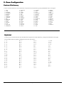
2. Zone Configuration
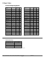
Zone Type Descriptions
Zone Type
1. Entry / Exit
Description
1) Away mode - this zone is always delayed (entry / exit).
2) Stay mode - this zone is always delayed (entry / exit).
3) Instant mode - this zone is always delayed exit and always instant alarm on entry.
1) Away mode - this zone is always an instant alarm.
2. Perimeter
2) Stay mode - this zone is always an instant alarm.
Instant
3) Instant mode - this zone is always an instant alarm.
1) Away mode - this zone responds as a follower.*
3. Interior 1
2) Stay mode - this zone responds as a follower. *
3) Instant mode - this zone responds as an instant alarm if activated.
1) Away mode - this zone responds as a follower. *
4. Interior 2
2) Stay mode - this zone is always bypassed.
3) Instant mode - this zone is always bypassed.
1) Away mode - this zone is always delayed
5. Interior 3
2) Stay mode - this zone is always delayed
3) Instant mode - this zone is always bypassed
1) This zone type is used for devices that will create an alarm regardless of the armed state of the SMDC.
6. 24 Hour
1) This type of zone may also be enable for Fire Supervisory after the YES has been programmed.
7. Fire
2) If YES is selected for Fire Supervisory, the keypad(s) will emit a steady tone on an alarm condition and display the zone
in alarm.
8. Day Zone
1) Disarmed - an activation creates an trouble condition.
2) Armed - an activation creates an instant alarm condition.
1) This zone type allows the zone to be open when arming the SMDC.
9. Garage Door
2) When the zone restores, it is returned as an active entry delay zone.
3) The zone must restore to a secure condition prior to exit delay time expiring.
4) Should the zone fail to secure, an exit error code will be transmitted if so programmed.
5) An alarm will be generated if the zone is left open.
* Note: The term follower is defined as the zone will be delayed on entry if the Exit door is sensed by the control panel first, should the follower zone be
sensed first by the control panel, the follower zone will create an alarm instantly.
Loop Type Descriptions
Loop Type
1. Normally Open
2.2K EOL
No
2. Normally Closed
No
3. Normally Open/
Normally Closed
Yes
4. Normally Open,
Trouble on Break
Yes
5. Normally Closed,
Trouble on Short
Yes
Description
1) For devices that have a Normally Open relay output.
2) Open will occur on a short.
3) No trouble conditions will be generated.
1) For devices that have a Normally Closed relay output.
2) Open condition will occur on a break.
3) No trouble conditions will be generated.
1) For devices that have a Normally Open or Normally Closed relay output.
2) Open will occur on a short or a break.
3) No trouble conditions will be generated.
1) For devices which have a Normally Open relay output.
2) Open condition will occur on a short
3) Trouble condition will occur on a break
4) Armed - Trouble report code transmitted if programmed on all zone types.
5) Disarmed - Trouble report code transmitted if programmed on zone type 6 (24 hr)- 7 (fire) only.
1) For devices which have a Normally Closed relay output.
2) Open will occur on a break
3) Trouble condition will occur on a short.
4) Armed - Trouble report code transmitted if programmed on all zone types.
5) Disarmed - Trouble report code transmitted if programmed on zone type 6 (24 hr)- 7 (fire) only.
Optex Inc. - 1845 W 205th St. - Torrance, Ca. 90501 - 800-966-7839
SMDC-16 Program Manual
21 of 59
3440-0252 A4
3. Receivers
This section details the requirements necessary for the transmission of signals, format type,
telephone line monitor responses, account number(s), radio options, and receiver reporting
options. Program each of the options as necessary for the installation.
3.1 Select Receiver #
SEL. RECEIVER
Selections: 1 or 2
Default: Blank
E x a m p l e : Press 1 for receiver 1 - Enter - Clear
3.1.1 Receiver 1
Once Receiver 1 is chosen, the display will scroll the following three options:
1. Telephone
2. Account Numbers
3. Formats
3.1.1.1 Telephone Number
TELEPHONE NUMBER
Selections: See below
Default: Blank
Select up to 16 digits/characters for the telephone number and any required delays or
access codes. (see chart below).
N o t e : Press the RESET key to clear the phone number presently displaying,
Selections:
Instant Key:
Memory Key:
Stay Key:
Away Key:
0
3
5
#
through 9
second dial pause (appears as a “:”)
second dial tone detect (appears as a”;”)
(pound)
* (asterisk)
3.1.1.2. Account Numbers
This section allows you to assign unique account numbers to various “packs” of zones.
Each “pack” consists of 8 zones.
N o t e : Always program Common Account Number if multiple account numbers
as this will write the account number to all locations.
This menu will scroll.:
(1) Account Z01-40
(2) Account Z41-80
(3) Account Groups
(4) Common Account Number (see note above).
3.1.1.2.1 Zone Account Numbers for Z 01-40
The bottom line will be scrolling the different sets of account numbers.
3.1.1.2.1.1 Zones 1-8
ACCOUNT Z01-08
Selections: 0000 - FFFF
0000
Default: 0000
Select the account number to be transmitted for zones 1-8.
3.1.1.2.1.2 Zones 9-16
3.1.1.2.1.3 Zones 17-24
3.1.1.2.1.4 Zones 25-32
3.1.1.2.1.5 Zones 33-40
3. Receivers
1. Select Receiver #
1. Receiver 1
1. Telephone Number
2. Account #
1. Acct # Z01-Z40
2. Acct # Z41-Z80
3. Partition Acct
4. Common Account #
3. Formats
2. Receiver 2
1. Telephone Number
2. Account #
1. Acct # Z01-Z40
2. Acct # Z41-Z80
3. Partition Acct
4. Common Account #
3. Formats
2. # of Telco Lines
3. Tel. Monitor Opt.
1. Monitor Both Lines
2. Keypad Audible
3. Bell 1 Output
4. Bell 2 Output
5. Relay 1 Output
6. Relay 2 Output
7. PGM 1 Output
8. PGM 2 Output
9. PGM 3 Output
4. Number of Dial Att.
5. Dial Features
1. TouchTone/Rotary
2. Fallback on Rotary
3. Delay before
4. TLM fault time
5. Anti-Jam Time
6. Comm. Fail Code
7. TLM Report Codes
1. TLM Fault
2. TLM Restore
are not needed
8. Rcvr Routing Options
1. Alarms
2. Open/Close
3. System
4. Partition #
1. Partition 1
2. Partition 2
3. Partition 3
4. Partition 4
5. Partition 5
6. Partition 6
7. Partition 7
8. Partition 8
Select the account number to be transmitted for zones 9-16.
Select the account number to be transmitted for zones 17-24.
Select the account number to be transmitted for zones 25-32.
Select the account number to be transmitted for zones 33-40.
.
Optex Inc. - 1845 W 205th St. - Torrance, Ca. 90501 - 800-966-7839
SMDC-16 Program Manual
22 of 59
3440-0252 A4
3. Receivers
1. Select Receiver #
1. Receiver 1
1. Telephone Number
Receiver 1(continued)
2. Account #
1. Acct # Z01-Z40
2. Acct # Z41-Z80
3.1.1.2.2 Zone Account Numbers for Z 41-80
3. Partition Acct
The bottom line will be scrolling different sets of account numbers
4. Common Account #
3.1.1.2.2.1 Zones 41-48
3. Formats
ACCOUNT Z41-48
Selections: 0000 - FFFF
2. Receiver 2
0000
Default: 0000
1. Telephone Number
2. Account #
Select the account number to be transmitted for zones 41-48.
1. Acct # Z01-Z40
2. Acct # Z41-Z80
3.1.1.2.2.2 Zones 49-56 Select the account number to be transmitted for zones 49-56.
3. Partition Acct
3.1.1.2.2.3 Zones 57-64 Select the account number to be transmitted for zones 57-64.
4. Common Account #
3.1.1.2.2.4 Zones 65-72 Select the account number to be transmitted for zones 65-72.
3. Formats
3.1.1.2.2.5 Zones 73-80 Select the account number to be transmitted for zones 73-80.
2. # of Telco Lines
3. Tel. Monitor Opt.
1. Monitor Both Lines
3.1.1.2.3 Partition Account Numbers
2. Keypad Audible
This section allows you to assign unique account numbers to various groups.
3. Bell 1 Output
N o t e : These Partition numbers will only be transmitted in a Partitioned System.
4. Bell 2 Output
N o t e : Always program Common Account Number if multiple account numbers are not needed 5. Relay 1 Output
6. Relay 2 Output
as this will write the account number to all locations.
7. PGM 1 Output
8. PGM 2 Output
3.1.1.2.3.1 Partition 1
9. PGM 3 Output
1 ACCOUNT GRP-1
Selections: 0000 - FFFF
4. Number of Dial Att.
0000
Default: 0000
5. Dial Features
Select the account number to be transmitted for Partition 1.
1. TouchTone/Rotary
2. Fallback on Rotary
3. Delay before
3.1.1.2.3.2. Partition 2 - Select the account number to be transmitted for Partition 2
4. TLM fault time
3.1.1.2.3.3. Partition 3 - Select the account number to be transmitted for Partition 3
5. Anti-Jam Time
3.1.1.2.3.4. Partition 4 - Select the account number to be transmitted for Partition 4
6. Comm. Fail Code
3.1.1.2.3.5. Partition 5 - Select the account number to be transmitted for Partition 5
7. TLM Report Codes
3.1.1.2.3.6. Partition 6 - Select the account number to be transmitted for Partition 6
1. TLM Fault
2. TLM Restore
3.1.1.2.3.7. Partition 7 - Select the account number to be transmitted for Partition 7
8. Rcvr Routing Options
3.1.1.2.3.8. Partition 8 - Select the account number to be transmitted for Partition 8
1. Alarms
2. Open/Close
3.1.1.2.4 Common Account Number
3. System
1 COMMON ACCOUNT
Selections: 0000 - FFFF
4. Partition #
0000
Default: 0000
1. Partition 1
2. Partition 2
Select the account number to be transmitted for all Groups and all zones
3. Partition 3
W a r n i n g : making an entry in this location will over-write the information to all account
4. Partition 4
number locations (partition and zone account numbers).
5. Partition 5
6. Partition 6
7. Partition 7
3.1.1.3 Format
8. Partition 8
RCVR#
FORMAT
Selections: See Table 3 below
3. Receivers
3.1.1
(scroll formats)
Default: 10PPS 3/1 Format
Select the transmission format will be for Receiver 1.
(see chart below and on page 27 for more detailed information).
Transmission Format Types
1. 10PPS 3/1
8. 20PPS 4/1
2. 10PPS 3/1 Extended
9. 20PPS 4/1 Extended
3. 10PPS 4/1
10. 20PPS 4/2
4. 10PPS 4/1 Extended
11. 40PPS with Parity
5. 10PPS 4/2
12. Varitech FSK 4/2
6. 20PPS 3/1
13. SIA Level 1
3.1.2
Receiver
7. 20PPS
3/12Extended
14. Ademco Contact ID
The programming sequence for Receiver 2 is identical to Receiver 1. Program the
necessary information as required for Receiver 2.
Optex Inc. - 1845 W 205th St. - Torrance, Ca. 90501 - 800-966-7839
SMDC-16 Program Manual
23 of 59
3440-0252 A4
3. Receivers
3.2 Number of Telco Lines
# of Telco Line
Selections: 00 - 02
01
Default: 01
Enter the number of phone lines that will be connected to the SMDC. (see wiring diagram).
N o t e : The panel will enunciate a telco fault should this option be enable for more lines
than are installed.
3.3 Telephone Monitor
Options
The information in this section focuses on how the SMDC will respond should the
telephone line(s) be compromised.
3.3.1 Monitor Both Lines
MONITOR BOTH
Selections: Yes / No
NO 0=NO 1= YES
Default: No
Enable this option to allow the SMDC to monitor the phone line current and voltage
of two phone lines.
3.3.2 Keypad Audible
KEYPAD AUDIBLE
Selections: Yes / No
NO 0=NO 1=YES
Default: No
Enable this option to allow the SMDC to enunciate a trouble condition at all
SMPC-32 should the SMDC detect a trouble condition on the phone line(s).
3.3.3 Bell 1 Output
BELL 1 OUTPUT
Selections: Yes / No
NO 0=NO 1=YES
Default: No
Enable this option to energize Bell 1 when the SMDC has detected a telco line fault
condition.
(see 1.2 Cutoff Times).
3.3.4 Bell 2 Output
BELL 2 OUTPUT
Selections: Yes / No
NO 0=NO 1=YES
Default: No
Enable this option to energize Bell 2 when the SMDC has detected a telco line fault
condition.
(see 1.2 Cutoff Times).
3.3.5 Relay 1 Output
RELAY 1 OUTPUT
Selections: Yes / No
NO 0=NO 1=YES
Default: No
Enable this option to energize Relay 1 when the SMDC has detected a telco line fault
condition.
(see 1.2 Cutoff Times).
3. Receivers
1. Select Receiver #
1. Receiver 1
1. Telephone Number
2. Account #
1. Acct # Z01-Z40
2. Acct # Z41-Z80
3. Partition Acct
4. Common Account #
3. Formats
2. Receiver 2
1. Telephone Number
2. Account #
1. Acct # Z01-Z40
2. Acct # Z41-Z80
3. Partition Acct
4. Common Account #
3. Formats
2. # of Telco Lines
3. Tel. Monitor Opt.
1. Monitor Both Lines
2. Keypad Audible
3. Bell 1 Output
4. Bell 2 Output
5. Relay 1 Output
6. Relay 2 Output
7. PGM 1 Output
8. PGM 2 Output
9. PGM 3 Output
4. Number of Dial Att.
5. Dial Features
1. TouchTone/Rotary
2. Fallback on Rotary
3. Delay before
4. TLM fault time
5. Anti-Jam Time
6. Comm. Fail Code
7. TLM Report Codes
1. TLM Fault
2. TLM Restore
8. Rcvr Routing Options
1. Alarms
2. Open/Close
3. System
4. Partition #
1. Partition 1
2. Partition 2
3. Partition 3
4. Partition 4
5. Partition 5
6. Partition 6
7. Partition 7
8. Partition 8
3.3.6 Relay 2 Output
RELAY 2 OUTPUT
Selections: Yes / No
NO 0=NO 1=YES
Default: No
Enable this option to energize Relay 2 when the SMDC has detected a telco line fault
condition.
(see 1.2 Cutoff Times).
3.3.7 PGM 1 Output
PGM-1 OUTPUT
Selections: Yes / No
NO 0=NO 1=YES
Default: No
Enable this option to energize PGM 1 when the SMDC has detected a telco line fault
condition.
(see 1.2 Cutoff Times).
Optex Inc. - 1845 W 205th St. - Torrance, Ca. 90501 - 800-966-7839
SMDC-16 Program Manual
24 of 59
3440-0252 A4
3. Receivers
3 . 3 . T e l e p h o n e M o n i t o r O p t i o n s (continued)
3.3.8 PGM 2 Output
PGM-2 OUTPUT
Selections: Yes / No
NO 0=NO 1=YES
Default: No
Enable this option to energize PGM 2 when the SMDC has detected a telco line fault
condition.
(see 1.2 Cutoff Times).
3.3.9 PGM 3 Output
PGM-3 OUTPUT
Selections: Yes /No
NO 0=NO 1=YES
Default: No
Enable this option to energize PGM 3 when the SMDC has detected a telco line fault
condition.
(see 1.2 Cutoff Times).
3.4 Number of Dial Attempts
NUMBER OF ATT
Selections: 1-15
05
Default: 5
Select the number of dial attempts the SMDC will try to reach the central station.
N o t e : This entry is applicable to both Receiver 1 and Receiver 2.
3.5 Dial Features
This section determines the characteristics of the dialing features.
3.5.1 Touch Tone / Rotary
TOUCH TONE
Selections: 1=TT, 0=Rotary
NO 0=NO 1=YES
Default: TT
Select whether the SMDC will attempt to dial in a Touch Tone or Rotary format.
(see 3.5.2 Rotary Fallback).
3.5.2 Fallback on Rotary
ROTARY BACKUP
Selections: Yes / No
NO 0=NO 1=YES
Default: No
You may select to have the SMDC “fallback” on rotary dialing should the signal
fail to reach the central station after the first Touch Tone attempt.
N o t e : All dialing attempts after the first Touch tone attempt will be rotary.
3.5.3 Delay Before Dial
DIAL DELAY
Selections: 0-99 seconds
00 seconds
Default: 00 seconds
Enter the appropriate amount of time to delay the communication of burglary alarm signals
to the central station to allow the user to abort the alarm transmission.
N o t e : This entry does not effect Fire alarms, Keypad Emergency or Duress alarms.
3. Receivers
1. Select Receiver #
1. Receiver 1
1. Telephone Number
2. Account #
1. Acct # Z01-Z40
2. Acct # Z41-Z80
3. Partition Acct
4. Common Account #
3. Formats
2. Receiver 2
1. Telephone Number
2. Account #
1. Acct # Z01-Z40
2. Acct # Z41-Z80
3. Partition Acct
4. Common Account #
3. Formats
2. # of Telco Lines
3. Tel. Monitor Opt.
1. Monitor Both Lines
2. Keypad Audible
3. Bell 1 Output
4. Bell 2 Output
5. Relay 1 Output
6. Relay 2 Output
7. PGM 1 Output
8. PGM 2 Output
9. PGM 3 Output
4. Number of Dial Att.
5. Dial Features
1. TouchTone/Rotary
2. Fallback on Rotary
3. Delay before
4. TLM fault time
5. Anti-Jam Time
6. Comm. Fail Code
7. TLM Report Codes
1. TLM Fault
2. TLM Restore
8. Rcvr Routing Options
1. Alarms
2. Open/Close
3. System
4. Partition #
1. Partition 1
2. Partition 2
3. Partition 3
4. Partition 4
5. Partition 5
6. Partition 6
7. Partition 7
8. Partition 8
3.5.4 TLM Fault Time
TLM FAULT TIME
Selections: 0-99
01 x 20 secs
Default: 1 x 20 seconds
Enter the period of time the phone line must be faulted before the SMDC will panel
will generate a TLM fault condition.
(see 3.7 TLM Report codes).
Optex Inc. - 1845 W 205th St. - Torrance, Ca. 90501 - 800-966-7839
SMDC-16 Program Manual
25 of 59
3440-0252 A4
3. Receivers
3 . 5 D i a l F e a t u r e s (continued)
3.5.5 Anti-Jam Time
ANTI JAM TIME
Selections: Yes / No
15 seconds
Default: 15 seconds
Select the amount of time required by your local telephone company to release the
line of an incoming call and produce dial tone for the next out going call.
N o t e : Consult your phone company for the correct time as the amount of time varies
by phone company.
3.6 Comm Fail Report Code
COMM FAIL RPT
Selections: 01-FF / Contact ID / SIA
code NO
Default: No Report
Select the Comm Fail report code that will be sent to the central station via the second
phone line or long range radio after the programmed number of dialing attempt on phone l
has been exhausted.
(see SIA-Contact ID-Hex charts pg 42 & 43).
3.7 TLM Report Codes
TLM (Telephone Line Monitor) Report Codes will be transmitted to the central station
on the remaining telephone line should a telephone line fault/restore condition occur for
approximately 30 seconds.
3.7.1 TLM Fault
TLM FAULT CODE
Selections: 01-FF / Contact ID / SIA
code NO
Default: No Report
Select the TLM fault report code that will be transmitted to the central when telephone line
fault condition occurs. (see 3.5.4-TLM Fault Time).
(see SIA-Contact ID-Hex charts pg 42 & 43).
3.7.2 TLM Restore
TLM RESTORE CODE
Selections: 01-FF / Contact ID / SIA
code NO
Default: No Report
Select the TLM restore report code that will be transmitted to the central when telephone line
fault condition has reset. (see 3.5.4-TLM Fault Time).
(see SIA-Contact ID-Hex charts pg 42 & 43).
3.8. Receiver Report Options
This section determines the destination of all reporting codes. Please note the following
chart for the selection for this options.
(see page 27 for additional information regarding routing).
1.
2.
3.
4.
5.
Rcvr 1 only
Rcvr 2 only
Rcvr 2 as a back-up for rcvr 1
Both Rcvrs
Rcvr 1 + radio
6.
7.
8.
9.
3. Receivers
1. Select Receiver #
1. Receiver 1
1. Telephone Number
2. Account #
1. Acct # Z01-Z40
2. Acct # Z41-Z80
3. Partition Acct
4. Common Account #
3. Formats
2. Receiver 2
1. Telephone Number
2. Account #
1. Acct # Z01-Z40
2. Acct # Z41-Z80
3. Partition Acct
4. Common Account #
3. Formats
2. # of Telco Lines
3. Tel. Monitor Opt.
1. Monitor Both Lines
2. Keypad Audible
3. Bell 1 Output
4. Bell 2 Output
5. Relay 1 Output
6. Relay 2 Output
7. PGM 1 Output
8. PGM 2 Output
9. PGM 3 Output
4. Number of Dial Att.
5. Dial Features
1. TouchTone/Rotary
2. Fallback on Rotary
3. Delay before
4. TLM fault time
5. Anti-Jam Time
6. Comm. Fail Code
7. TLM Report Codes
1. TLM Fault
2. TLM Restore
8. Rcvr Routing Options
1. Alarms
2. Open/Close
3. System
4. Partition #
1. Partition 1
2. Partition 2
3. Partition 3
4. Partition 4
5. Partition 5
6. Partition 6
7. Partition 7
8. Partition 8
Rcvr 2 + radio
Rcvr 2 back-up to 1 + radio
Rcvr one and Rcvr two + radio
Radio only
3.8.1 Alarms Codes
ALARM ROUTING =1
Selections: 1-4
(Scrolling 1-4)
Default: 1
Enter the number that correspond to the option that will determines how all the alarm
reporting codes will be transmitted to the central station.
N o t e : You may only select receiver options 1 to 4 for alarms.
(see page 27 for additional information regarding routing).
Optex Inc. - 1845 W 205th St. - Torrance, Ca. 90501 - 800-966-7839
SMDC-16 Program Manual
26 of 59
3440-0252 A4
3. Receivers
3.8. Receiver Report Options
3.8.2 Open / Close Codes
OP/CL ROUTING =1
Selections: 1-10 (10 = none)
(Scrolling 1-9)
Default: 1
Enter the number that correspond to the option that will determines how all the Open/Close
reporting codes will be transmitted to the central station.
(see page 27 for additional information regarding routing).
3.8.3 System Codes
SYSTEM ROUTING =1
Selections: 1-10 (10 = none)
(Scrolling 1-9)
Default: 1
Enter the number that correspond to the option that will determines how all the System
reporting codes will be transmitted to the central station.
(see page 27 for additional information regarding routing).
3.8.4. Partition Routing Options
This section determines the destination of all reporting codes pertaining to each partition.
Please note the chart on the selection chart on the preceding page for this options.
N o t e : this routing is applicable only in a Keypad Partitioned System.
SET PART NUMBER
Selections: 1-8
PARTITION
Default: Blank
Enter the partition number that you wish to program. Press ENTER, CLEAR.
3.8.4.1 Partition 1
PART -1 ROUTING =1
Selections: 1-10 (10 = none)
(Scrolling 1-9)
Default: 1
Enter the number that correspond to the option that will determines how the system
reporting codes will be transmitted to the central station.
(see page 27 for additional information regarding routing).
3.8.4.2 Partition 2 - Program in the same manner as Partition 1.
3.8.4.3 Partition 3 - Program in the same manner as Partition 1.
3.8.4.4 Partition 4 - Program in the same manner as Partition 1.
3.8.4.5 Partition 5 - Program in the same manner as Partition 1.
3.8.4.6 Partition 6 - Program in the same manner as Partition 1.
3.8.4.7 Partition 7 - Program in the same manner as Partition 1.
3.8.4.8 Partition 8 - Program in the same manner as Partition 1.
3.9 Radio Options
This option determines the characteristics of the radio system.
(Additional hardware required)
3. Receivers
1. Select Receiver #
1. Receiver 1
1. Telephone Number
2. Account #
1. Acct # Z01-Z40
2. Acct # Z41-Z80
3. Partition Acct
4. Common Account #
3. Formats
2. Receiver 2
1. Telephone Number
2. Account #
1. Acct # Z01-Z40
2. Acct # Z41-Z80
3. Partition Acct
4. Common Account #
3. Formats
2. # of Telco Lines
3. Tel. Monitor Opt.
1. Monitor Both Lines
2. Keypad Audible
3. Bell 1 Output
4. Bell 2 Output
5. Relay 1 Output
6. Relay 2 Output
7. PGM 1 Output
8. PGM 2 Output
9. PGM 3 Output
4. Number of Dial Att.
5. Dial Features
1. TouchTone/Rotary
2. Fallback on Rotary
3. Delay before
4. TLM fault time
5. Anti-Jam Time
6. Comm. Fail Code
7. TLM Report Codes
1. TLM Fault
2. TLM Restore
8. Rcvr Routing Options
1. Alarms
2. Open/Close
3. System
4. Partition #
1. Partition 1
2. Partition 2
3. Partition 3
4. Partition 4
5. Partition 5
6. Partition 6
7. Partition 7
8. Partition 8
3.9.1 Radio Attempt
RADIO ATTEMPTS
Selections: 00 - 10
00
Default: 00
Select the number of radio attempts that will be made to transmit all signals to the central
station.
N o t e : . The radio will not attempt further transmissions once the digital signal has been “kissed off”.
3.9.2 Radio First
RADIO FIRST
Selections: Yes / No
NO 0=NO 1=YES
Default: No
Enable this option for the first radio signal to be transmitted to the central station prior to a digital
dialing attempt.
3.9.4 Radio Account Numbers
Do not program unless Optex Radio will be installed.
Optex Inc. - 1845 W 205th St. - Torrance, Ca. 90501 - 800-966-7839
SMDC-16 Program Manual
27 of 59
3440-0252 A4
3. Receivers
Receiver Information
All central station receivers have different types of line cards that are capable of accepting or not accepting certain formats. Therefore it is recommended
that you contact the technical support group at your central station to determine the fastest and most reliable format available.
Accepted Receivers
#
Format Name
Description
VaritechAdemco SK FBI
1
10PPS 3-1
10 pulses per second - 3 digit account number - 1 digit report code
Varitech- Ademco SK FBI
2
10PPS 3-1 EXT
10 pulses per second - 3 digit account number - 1 digit report code w/ extended 2 digit
Varitech- Ademco SK FBI
3
10PPS 4-1
10 pulses per second - 4 digit account number - 1 digit report code
Varitech- Ademco SK FBI
4
10PPS 4-1 EXT
10 pulses per second - 4 digit account number - 1 digit report code w/ extended 2 digit
Varitech- Ademco SK FBI
5
10PPS 4-2
10 pulses per second - 4 digit account number - 2 digit report code
Varitech- Ademco SK FBI
6
20PPS 3-1
20 pulses per second - 3 digit account number - 1 digit report code
Varitech- Ademco SK FBI
7
20PPS 3-1 EXT
20 pulses per second - 3 digit account number - 1 digit report code w/ extended 2 digit
Varitech- Ademco SK FBI
8
20PPS 4-1
20 pulses per second - 4 digit account number - 1 digit report code
Varitech- Ademco SK FBI
9
20PPS 4-1 EXT
20 pulses per second - 4 digit account number - 1 digit report code w/ extended 2 digit
Varitech- Ademco SK FBI
10
20PPS 4-2
20 pulses per second - 4 digit account number - 2 digit report code
Varitech- Ademco SK FBI
11
40PPS W/PARITY
40 pulses per second - 3 digit account number - 1 digit report code
Varitech
12
VAR FSK 4-2
Tones (no pulses) - 4 digit account number - 2 digit report code
Check w/central station
13
SIA LEVEL 1
Tone (no pulses)
- 4 digit account number - zone type w/zone number in English
Check w/central station
14
CONTACT ID
Tone (no pulses)
- 4 digit account number - zone type w/zone number in English
Receiver Routing Options
The chart below indicates all reporting options in alphabetical order and the individual receiver routing.
Report Codes
Menu
Rcvr
Report Codes
Menu
Routing
2-Wire Smk Alarm
2-Wire Smk Restore
2-Wire Smk Trbl
Abnormal Self Test
AC Fail
AC Restore
Auto Arm Code
Auto Arm Fail
Aux. Power Fail
Aux. Power Restore
Battery Low
Battery Restore
Bell Fault Restore
Bell Fault Trouble
Bell Restore
Box Tamper
Box Tamper Restore
Bus Fault
Bus Restore
Close Code (all)
Close Code (user)
Close Exception
Comm Fail
Duress
4.6.1
4.6.3
4.6.2
1.3.5
5.1.1
5.1.2
8.3.2
8.3.3
5.3.4
5.3.5
5.1.3
5.1.4
5.1.8
5.1.7
5.2.3
5.1.5
5.1.6
5.2.1
5.2.2
6.4.2
6.4.4
5.2.7
3.6
5.1.9
Legend 3.8.1 = Alarm Codes /
3.8.1.
3.8.1.
3.8.1.
3.8.3.
3.8.3.
3.8.3.
3.8.2.
3.8.2.
3.8.3.
3.8.3.
3.8.3.
3.8.3.
3.8.3.
3.8.3.
3.8.3.
3.8.3.
3.8.3.
3.8.3.
3.8.3.
3.8.2.
3.8.2.
3.8.2.
3.8.3.
3.8.3.
Emergency Report
Enter Install. Prog
Exit Error
Exit Install. Prog.
Force Arm
Ground Fault
No Trip Code
O/C Buffer Full
O/C Buffer Over
On Premise Arm
Open Code (all)
Open Code (user)
Open Exception
Open Restore
Self Test
Special PIN
TLM Fault
TLM Restore
Unauthorized User
Zone Alarm
Zone Bypass
Zone Cancel
Zone Restore
Zone Trouble
3.8.2 = Open\Close Codes
Optex Inc. - 1845 W 205th St. - Torrance, Ca. 90501 - 800-966-7839
Rcvr
Routing
/
SMDC-16 Program Manual
28 of 59
4.5.2
5.2.8
5.2.5
5.2.9
5.3.7
5.3.6
2.8
5.3.1
5.3.2
5.3.8
6.4.1
6.4.3
5.2.6
5.2.4
1.3.4
5.3.9
3.7.1
3.7.2
5.3.3
2.3.1
2.3.3
2.3.4
2.3.5
2.3.2
3.8.3 = System Codes
3440-0252 A4
3.8.3.
3.8.3.
3.8.2.
3.8.3.
3.8.2.
3.8.3.
3.8.3.
3.8.2.
3.8.2.
3.8.2.
3.8.2.
3.8.2.
3.8.2.
3.8.2.
3.8.3.
3.8.3.
3.8.3.
3.8.3.
3.8.3.
3.8.1
3.8.1
3.8.1
3.8.1
3.8.1
4. System Options
1. Monitor Mode
1. Ack Required
2. Scroll Open Zones
3. Scroll Bypass
4. Silent Mon. Mode
This section determines the various options that are available for Monitor Mode,
5. Auto Mon on Disarm
Walk Test, System Features, System Messages, Emergency, 2 Wire Smoke and
6. PIN Entry Required
Force Arming capabilities. Within each of these sub-menus, select the necessary
7. Outputs
options that are required for the installation.
1. Bell 1
2. Bell 2
Monitor Mode
3. Relay 1
4. Relay 2
N o t e : see chart on page 29 for detailed operation.
5. PGM 1
6. PGM 2
4.1.1 Ack Required
7. PGM 3
ACKNOWLEDGE
Selections: Yes / No
2. Walk Test Mode
NO 0=NO 1=YES
1. Bell 1
Default: No
2. Bell 2
Enable to option if the outputs assigned to Monitor will be continuous or monetary
3. Relay 1
(monetary if Ack = no / continuous if Ack = yes)
4. Relay 2
5. PGM 1
4.1.2 Scroll Open Zones
6. PGM 2
SCROLL OPEN
Selections: Yes / No
7. PGM 3
NO 0=NO 1=YES
Default: No
3. System Features
1. Hist. View by User
Enable this option for the non-secure zones will scroll on the keypad(s).
2. O/C View by User
3. Silent Trouble
4.1.3 Scroll Bypass Zones
4. Not Used - Reserved
SCROLL BYPASS
Selections: Yes / No
5. 50Hz/60Hz
NO 0=NO 1=YES
Default: No
6. AC/Crystal
Enable this option for the keypads to scroll all bypassed zones while the SMDC
7. Pwr Dly Time
is in the Monitor mode. (see 2.7.4 Bypass Allowed).
8. PIN Require for Scan
9. Threshold Bad Codes
4. System Messages
4.1.4 Silent Monitor Mode
1. Top Line Display
SILENT MODE
Selections: Yes / No
1. Grp/Part 1 Display
NO 0=NO 1=YES
Default: No
7-8. Group/Part Display
Enable this option for all of the installed keypads to be silent in the Monitor mode.
2. Disarmed Nml Msg
3. Disarmed Abnml Msg
5. Emergency
4.1.5 Auto Monitor on Disarm
1. Emergency Enabled
MON ON DISARM
Selections: Yes / No
2. Emergency Rpt
NO 0=NO 1=YES
Default: No
3. Bell 1 Output
Enable this option for the SMDC to be automatically placed in the Monitor Mode
4. Bell 2 Output
upon disarming.
5. Relay 1 Output
N o t e : This option will not function if an alarm condition has taken place during the
6. Relay 2 Output
7. PGM 1 Output
armed state.
8. PGM 2 Output
9. PGM 3 Output
4.1.6 PIN Entry Required
6. 2 Wire Smk
PIN REQUIRED
Selections: Yes / No
1. Alarm Report
NO 0=NO 1=YES
Default: No
2. Trouble Report
Enable this option if the installation requires that an authorized user PIN be used to enter
3. Smoke Restore
the Monitor Mode.
4. Smoke Reset
N o t e : This option should be set for yes if the keypad will be installed in a public access area.5. Alarm Verify
6. Outputs
1. Bell 1 Output
4.1.7 Monitor Outputs
2. Bell 1 Pulse
This sections determines which output(s) will activate when a zone is activated during
3. Bell 2 Output
the Monitor Mode (see 2.7.8 Monitor).
4. Bell 2 Pulse
5. Relay 1 Output
6. Relay 2 Output
4.1.7.1 Bell 1
7. PGM 1 Output
BELL OUTPUT 1
Selections: Yes / No
8. PGM 2 Output
NO 0=NO 1=YES
Default: No
9. PGM 3 Output
Enable this option for the SMDC to activate the Bell 1 output when a Monitor Mode
7. Force Arming Enabled
zone is activated. (see 4.1.1 Ack Required).
8. PGM / INP Functions
1. PGM 1 Function
2. PGM 2 Function
3. PGM 3 Function
4. INP-1 Function
4. System Options
4.1.
Optex Inc. - 1845 W 205th St. - Torrance, Ca. 90501 - 800-966-7839
SMDC-16 Program Manual
29 of 59
3440-0252 A4
4. System Options
4 . 1 . M o n i t o r M o d e (continued)
4.1.7.2 Bell 2
BELL OUTPUT 2
Selections: Yes / No
NO 0=NO 1=YES
Default: No
Enable this option for the SMDC to activate the Bell 2 output when a Monitor Mode
zone is activated. (see 4.1.1 Ack Required).
4.1.7.3 Relay 1
RELAY OUTPUT 1
Selections: Yes / No
NO 0=NO 1=YES
Default: No
Enable this option for the SMDC to activate the Relay 1 output when a Monitor Mode
zone is activated. (see 4.1.1 Ack Required).
4.1.7.4 Relay 2
RELAY OUTPUT 2
Selections: Yes / No
NO 0=NO 1=YES
Default: No
Enable this option for the SMDC to activate the Relay 2 output when a Monitor Mode
zone is activated. (see 4.1.1 Ack Required).
4.1.7.5 PGM 1
PGM OUTPUT 1
Selections: Yes / No
NO 0=NO 1=YES
Default: No
Enable this option for the SMDC to activate the PGM 1 output when a Monitor Mode
zone is activated. (see 4.1.1 Ack Required).
4.1.7.6 PGM 2
PGM OUTPUT 2
Selections: Yes / No
NO 0=NO 1=YES
Default: No
Enable this option for the SMDC to activate the PGM 2 output when a Monitor Mode
zone is activated. (see 4.1.1 Ack Required).
4.1.7.7 PGM 3
PGM OUTPUT 3
Selections: Yes / No
NO 0=NO 1=YES
Default: No
Enable this option for the SMDC to activate the PGM 3 output when a Monitor Mode
zone is activated. (see 4.1.1 Ack Required).
Monitor Mode Operation
Zone Type
1. Entry Exit
2. Perm. Instant
3. Interior 1
4. Interior 2
5. Interior 3
6. 24 Hour
7. Fire
8. Day Zone
9. Garage
1. Entry Exit
2. Perm. Instant
3. Interior 1
4. Interior 2
5. Interior 3
6. 24 Hour
7. Fire
8. Day Zone
9. Garage
Prog’d Yes/No and Results
Yes = Monitor outputs only (no report)
Yes = Monitor outputs only (no report)
Yes = Monitor outputs only (no report)
Yes = Monitor outputs only (no report)
Yes = Monitor outputs only (no report)
Yes = Alarm Reported / alarm outputs activated
Yes = Alarm Reported / alarm outputs activated
Yes = Alarm Reported / alarm outputs activated
Yes = Monitor outputs only (no report)
No = No Activation (no report)
No = No Activation (no report)
No = No Activation (no report)
No = No Activation (no report)
No = No Activation (no report)
No = Alarm Reported / alarm outputs activated
No = Alarm Reported / alarm outputs activated
No = Alarm Reported / alarm outputs activated
No = No Activation (no report)
Optex Inc. - 1845 W 205th St. - Torrance, Ca. 90501 - 800-966-7839
KP Display
Yes
Yes
Yes
Yes
Yes
Yes
Yes
Yes
Yes
No
No
No
No
No
No
No
No
No
SMDC-16 Program Manual
30 of 59
4. System Options
1. Monitor Mode
1. Ack Required
2. Scroll Open Zones
3. Scroll Bypass
4. Silent Mon. Mode
5. Auto Mon on Disarm
6. PIN Entry Required
7. Outputs
1. Bell 1
2. Bell 2
3. Relay 1
4. Relay 2
5. PGM 1
6. PGM 2
7. PGM 3
2. Walk Test Mode
1. Bell 1
2. Bell 2
3. Relay 1
4. Relay 2
5. PGM 1
6. PGM 2
7. PGM 3
3. System Features
1. Hist. View by User
2. O/C View by User
3. Silent Trouble
4. Not Used - Reserved
5. 50Hz/60Hz
6. AC/Crystal
7. Pwr Dly Time
8. PIN Require for Scan
9. Threshold Bad Codes
4. System Messages
1. Top Line Display
1. Grp/Part 1 Display
7-8. Group/Part Display
2. Disarmed Nml Msg
3. Disarmed Abnml Msg
5. Emergency
1. Emergency Enabled
2. Emergency Rpt
3. Bell 1 Output
4. Bell 2 Output
5. Relay 1 Output
6. Relay 2 Output
7. PGM 1 Output
8. PGM 2 Output
9. PGM 3 Output
6. 2 Wire Smk
1. Alarm Report
2. Trouble Report
3. Smoke Restore
4. Smoke Reset
5. Alarm Verify
6. Outputs
1. Bell 1 Output
2. Bell 1 Pulse
3. Bell 2 Output
4. Bell 2 Pulse
5. Relay 1 Output
6. Relay 2 Output
7. PGM 1 Output
8. PGM 2 Output
9. PGM 3 Output
7. Force Arming Enabled
8. PGM / INP Functions
1. PGM 1 Function
2. PGM 2 Function
3. PGM 3 Function
4. INP-1 Function
3440-0252 A4
4. System Options
4.2 Walk Test Mode
This sections determines which output(s) will activate when a zone (programmed as a
Walk Test zone) is activated during a Walk Test. (See 2.7.7. Walk Test)
4.2.1 Bell 1
BELL OUTPUT 1
Selections: Yes / No
NO 0=NO 1=YES
Default: No
Enable this option for the SMDC to activate the Bell 1 output for 2 seconds (only)
when a zone is activated during a Walk Test. (see 2.7.7. Walk Test).
4.2.2 Bell 2
BELL OUTPUT 2
Selections: Yes / No
NO 0=NO 1=YES
Default: No
Enable this option for the SMDC to activate the Bell 2 output for 2 seconds (only)
when a zone is activated during a Walk Test. (see 2.7.7. Walk Test).
4.2.3 Relay 1
RELAY OUTPUT 1
Selections: Yes / No
NO 0=NO 1=YES
Default: No
Enable this option for the SMDC to activate the Relay 1 output for 2 seconds (only)
when a zone is activated during a Walk Test. (see 2.7.7. Walk Test).
4.2.4 Relay 2
RELAY OUTPUT 2
Selections: Yes / No
NO 0=NO 1=YES
Default: No
Enable this option for the SMDC to activate the Relay 2 output for 2 seconds (only)
when a zone is activated during a Walk Test. (see 2.7.7. Walk Test).
4.2.5 PGM 1
PGM OUTPUT 1
Selections: Yes / No
NO 0=NO 1=YES
Default: No
Enable this option for the SMDC to activate the PGM 1 output for 2 seconds (only)
when a zone is activated during a Walk Test. (see 2.7.7. Walk Test).
4.2.6 PGM 2
PGM OUTPUT 2
Selections: Yes / No
NO 0=NO 1=YES
Default: No
Enable this option for the SMDC to activate the PGM 2 output for 2 seconds (only)
when a zone is activated during a Walk Test. (see 2.7.7. Walk Test).
4.2.7 PGM 3
PGM OUTPUT 3
Selections: Yes / No
NO 0=NO 1=YES
Default: No
Enable this option for the SMDC to activate the PGM 3 output for 2 seconds (only)
when a zone is activated during a Walk Test. (see 2.7.7. Walk Test).
4.3 System Features
This section defines has the user may interact with the SMDC with history viewing
operation of the clock, power delays of the SMDC.
4.3.1 History View by User
HIST VIEW USER
Selections: Yes / No
YES 0=NO 1=YES
Default: Yes
Enable this option to allow the users to view all historical events that have occurred.
(see 0 Pager/Fax/Printer / users manual).
N o t e : The SMDC control/communicator is able to log 512 total events.
Optex Inc. - 1845 W 205th St. - Torrance, Ca. 90501 - 800-966-7839
SMDC-16 Program Manual
31 of 59
4. System Options
1. Monitor Mode
1. Ack Required
2. Scroll Open Zones
3. Scroll Bypass
4. Silent Mon. Mode
5. Auto Mon on Disarm
6. PIN Entry Required
7. Outputs
1. Bell 1
2. Bell 2
3. Relay 1
4. Relay 2
5. PGM 1
6. PGM 2
7. PGM 3
2. Walk Test Mode
1. Bell 1
2. Bell 2
3. Relay 1
4. Relay 2
5. PGM 1
6. PGM 2
7. PGM 3
3. System Features
1. Hist. View by User
2. O/C View by User
3. Silent Trouble
4. Not Used - Reserved
5. 50Hz/60Hz
6. AC/Crystal
7. Pwr Dly Time
8. PIN Require for Scan
9. Threshold Bad Codes
4. System Messages
1. Top Line Display
1. Grp/Part 1 Display
7-8. Group/Part Display
2. Disarmed Nml Msg
3. Disarmed Abnml Msg
5. Emergency
1. Emergency Enabled
2. Emergency Rpt
3. Bell 1 Output
4. Bell 2 Output
5. Relay 1 Output
6. Relay 2 Output
7. PGM 1 Output
8. PGM 2 Output
9. PGM 3 Output
6. 2 Wire Smk
1. Alarm Report
2. Trouble Report
3. Smoke Restore
4. Smoke Reset
5. Alarm Verify
6. Outputs
1. Bell 1 Output
2. Bell 1 Pulse
3. Bell 2 Output
4. Bell 2 Pulse
5. Relay 1 Output
6. Relay 2 Output
7. PGM 1 Output
8. PGM 2 Output
9. PGM 3 Output
7. Force Arming Enabled
8. PGM / INP Functions
1. PGM 1 Function
2. PGM 2 Function
3. PGM 3 Function
4. INP-1 Function
3440-0252 A4
4. System Options
4.3. System Features
(continued)
4.3.2 O/C View by User
OP/CL VIEW USER
Selections: Yes / No
YES 0=NO 1=YES
Default: Yes
Enable this option to allow the users to view all opening and closing historical events that
have occurred. (see 0 Pager/Fax/Printer / users manual).
4.3.3 Silent Trouble
SILENT TRBL
Selections: Yes / No
NO 0=NO 1=YES
Default: No
Enable this option for all SMPCs to be silent if a trouble condition occurs between the
hours of 9:00pm to 7:00am. Note: Not for Fire Alarm System Installations.
4.3.4 Not Used / Reserved for Future Use
Not Used / Reserved for
Future Use
4.3.5 50Hz / 60Hz
50 HZ
Selections: 50Hz / 60Hz
NO 0=NO 1=YES
Default: 60Hz
Enable this option to allow the SMDC to operate on 60Hz or 50Hz
(see 1.4-Time Clock)
4.3.6 AC/Crystal Clock
CRYSTAL CLOCK
Selections: AC / Crystal
NO 0=NO 1=YES
Default: AC
Enable this option to allow the clock to operate on a crystal or AC cycles.
(see 1.4 Time Clock Options).
N o t e : AC cycles will allow for a accurate clock operation.
4.3.7 Power Delay Time before Zone Processing
POWER UP DELAY
Selections: Blank, 01-99 seconds
10 seconds
Default: 10 seconds
Enable this option to allow the SMDC to ignore the zone’s status upon the return
of AC and DC power.
N o t e : This option is especially helpful when motion detectors or other powered devices
connected to the SMDC need a period of time to stabilize after power has restored to
the SMDC.
4.3.8 PIN Entry Required for Zone Scan
PIN FOR SCAN
Selections: Yes / No
YES 0=NO 1=YES
Default: Yes
Enable this option to require an authorized user PIN to perform a zone scan.
(see User Manual for levels).
4.3.9. Threshold of Bad Codes
# OF BAD CODES
Selections: Blank, 1-99
00
Default: 00
Enable this option to allow the SMDC to send an Unauthorized User report code to the
central station after the programmed number of consecutive unauthorized attempts to secure
a PIN has been entered at a keypad
(see 5.3.3 Unauthorized User report code).
Optex Inc. - 1845 W 205th St. - Torrance, Ca. 90501 - 800-966-7839
SMDC-16 Program Manual
32 of 59
4. System Options
1. Monitor Mode
1. Ack Required
2. Scroll Open Zones
3. Scroll Bypass
4. Silent Mon. Mode
5. Auto Mon on Disarm
6. PIN Entry Required
7. Outputs
1. Bell 1
2. Bell 2
3. Relay 1
4. Relay 2
5. PGM 1
6. PGM 2
7. PGM 3
2. Walk Test Mode
1. Bell 1
2. Bell 2
3. Relay 1
4. Relay 2
5. PGM 1
6. PGM 2
7. PGM 3
3. System Features
1. Hist. View by User
2. O/C View by User
3. Silent Trouble
4. Not Used - Reserved
5. 50Hz/60Hz
6. AC/Crystal
7. Pwr Dly Time
8. PIN Require for Scan
9. Threshold Bad Codes
4. System Messages
1. Top Line Display
1. Grp/Part 1 Display
7-8. Group/Part Display
2. Disarmed Nml Msg
3. Disarmed Abnml Msg
5. Emergency
1. Emergency Enabled
2. Emergency Rpt
3. Bell 1 Output
4. Bell 2 Output
5. Relay 1 Output
6. Relay 2 Output
7. PGM 1 Output
8. PGM 2 Output
9. PGM 3 Output
6. 2 Wire Smk
1. Alarm Report
2. Trouble Report
3. Smoke Restore
4. Smoke Reset
5. Alarm Verify
6. Outputs
1. Bell 1 Output
2. Bell 1 Pulse
3. Bell 2 Output
4. Bell 2 Pulse
5. Relay 1 Output
6. Relay 2 Output
7. PGM 1 Output
8. PGM 2 Output
9. PGM 3 Output
7. Force Arming Enabled
8. PGM / INP Functions
1. PGM 1 Function
2. PGM 2 Function
3. PGM 3 Function
4. INP-1 Function
3440-0252 A4
4. System Options
4.4. System Messages
This section allows you to customize the text on the top and bottom line of the keypad during
normal and abnormal conditions. (see 1.4.3 Display Clock for User)
4.4.1 Top Line Display
Each of the eight available Groups / Partitions may have their own customized line of text
for the top line.
N o t e : This text will be common to both Partitioning and Groups.
4.4. 1.1 Group / Partition 1
GRP-1 DISPLAY
Selections: Up to 16 characters
GRP-1
Default: GRP-#
Enter up to 16 characters as necessary for the top line of the keypad display.
(select words or letters from the chart on page 19).
4.4.1.2 Group / Partition 2 - Enter up to 16 characters as necessary.
4.4.1.3 Group / Partition 3 - Enter up to 16 characters as necessary.
4.4.1.4 Group / Partition 4 - Enter up to 16 characters as necessary.
4.4.1.5 Group / Partition 5 - Enter up to 16 characters as necessary.
4.4.1.6 Group / Partition 6 - Enter up to 16 characters as necessary.
4.4.1.7 Group / Partition 7 - Enter up to 16 characters as necessary.
4.4.1.8 Group / Partition 8 - Enter up to 16 characters as necessary.
4.4.2 Disarmed Normal Message
DIS NORM MSG
Selections: Up to 16 characters
READY TO ARM
Default: Ready To Arm
Enter up to 16 characters as necessary for the bottom line of the keypad display when
all zones are in a secured condition
(This text will be common to both Partitioning and Groups).
(select words or letters from the chart on page 19).
4.4.3 Disarmed Abnormal Message
DIS. ABN MSG
Selections: Up to 16 characters
SECURE TO ARM
Default: Secure To Arm
Enter up to 16 characters as necessary for the bottom line of the keypad display when zone(s)
are open or shorted. (This text will be common to both Partitions and Grps).
(select words or letters from the chart on page 19).
4.5. Emergency
This option determines the characteristics of the keypad Emergency buttons.
4.5.1 Emergency Enable
EMER. ENABLE
Selections: Yes / No
NO 0=NO 1=YES
Default: No
Enable to option to allow the Select Emergency keys on the SMDC to operate.
N o t e : the buttons must be pressed simultaneously
(see 4.5.2 Emergency Code - 4.5.3 Emergency outputs)
4.5.2 Emergency Report Code
EMER. RPT CODE
Selections: 01-FF / Contact ID / SIA
code NO
Default: No Report
Enter the report code that will be transmitted to the central station when the Emergency
keys are pressed.
(see SIA-Contact ID-Hex charts on pg 42 & 43).
4.5.3 Bell 1
BELL OUTPUT 1
Selections: Yes / No
NO 0=NO 1=YES
Default: No
Enable this option to activate Bell 1 output when the Emergency keys have been activated.
(see 2.2.1-Cutoff Times / 4.5.1-Emergency Enable).
Optex Inc. - 1845 W 205th St. - Torrance, Ca. 90501 - 800-966-7839
SMDC-16 Program Manual
33 of 59
4. System Options
1. Monitor Mode
1. Ack Required
2. Scroll Open Zones
3. Scroll Bypass
4. Silent Mon. Mode
5. Auto Mon on Disarm
6. PIN Entry Required
7. Outputs
1. Bell 1
2. Bell 2
3. Relay 1
4. Relay 2
5. PGM 1
6. PGM 2
7. PGM 3
2. Walk Test Mode
1. Bell 1
2. Bell 2
3. Relay 1
4. Relay 2
5. PGM 1
6. PGM 2
7. PGM 3
3. System Features
1. Hist. View by User
2. O/C View by User
3. Silent Trouble
4. Not Used - Reserved
5. 50Hz/60Hz
6. AC/Crystal
7. Pwr Dly Time
8. PIN Require for Scan
9. Threshold Bad Codes
4. System Messages
1. Top Line Display
1. Grp/Part 1 Display
7-8. Group/Part Display
2. Disarmed Nml Msg
3. Disarmed Abnml Msg
5. Emergency
1. Emergency Enabled
2. Emergency Rpt
3. Bell 1 Output
4. Bell 2 Output
5. Relay 1 Output
6. Relay 2 Output
7. PGM 1 Output
8. PGM 2 Output
9. PGM 3 Output
6. 2 Wire Smk
1. Alarm Report
2. Trouble Report
3. Smoke Restore
4. Smoke Reset
5. Alarm Verify
6. Outputs
1. Bell 1 Output
2. Bell 1 Pulse
3. Bell 2 Output
4. Bell 2 Pulse
5. Relay 1 Output
6. Relay 2 Output
7. PGM 1 Output
8. PGM 2 Output
9. PGM 3 Output
7. Force Arming Enabled
8. PGM / INP Functions
1. PGM 1 Function
2. PGM 2 Function
3. PGM 3 Function
4. INP-1 Function
3440-0252 A4
4. System Options
4.5. Emergency (continued)
4.5.4 Bell 2
BELL OUTPUT 2
Selections: Yes / No
NO 0=NO 1=YES
Default: No
Enable this option to activate Bell 2 output when the Emergency keys have been activated.
(see 2.2.1-Cutoff Times / 4.5.1-Emergency Enable).
4.5.5 Relay 1
RELAY OUTPUT 1
Selections: Yes / No
NO 0=NO 1=YES
Default: No
Enable this option to activate Relay 1 output when the Emergency keys have been activated.
(see 2.2.1-Cutoff Times / 4.5.1-Emergency Enable).
4.5.6 Relay 2
RELAY OUTPUT 2
Selections: Yes / No
NO 0=NO 1=YES
Default: No
Enable this option to activate Relay 2 output when the Emergency keys have been activated.
(see 2.2.1-Cutoff Times / 4.5.1-Emergency Enable).
4.5.7 PGM 1
PGM OUTPUT 1
Selections: Yes / No
NO 0=NO 1=YES
Default: No
Enable this option to activate PGM 1 output when the Emergency keys have been activated.
(see 2.2.1-Cutoff Times / 4.5.1-Emergency Enable).
4.5.8 PGM 2
PGM OUTPUT 2
Selections: Yes / No
NO 0=NO 1=YES
Default: No
Enable this option to activate PGM 2 output when the Emergency keys have been activated.
(see 2.2.1-Cutoff Times / 4.5.1-Emergency Enable).
4.5.9 PGM 3
PGM OUTPUT 3
Selections: Yes / No
NO 0=NO 1=YES
Default: No
Enable this option to activate PGM 3 output when the Emergency keys have been activated.
(see 2.2.1-Cutoff Times / 4.5.1-Emergency Enable).
4.6. Two Wire Smoke
This section determines the characteristics of the 2 wire smoke detector The maximum
number of 2 wire smoke detectors connected to this loop may not exceed 10 for UL
installations. Please refer to the SMDC Hookup Diagram for the compatibility listing
of 2 wire smoke detectors.
4.6.1 Alarm Report Code
ALARM RPT CODE
Selections: 01-FF / Contact ID / SIA
code NO
Default: No Report
Select the report code that will be transmitted to the central station when an alarm condition
is sensed on the 2 wire smoke detector circuit. (see wiring diagram / 3.8.3-Rcvr Routing /
SIA-Contact ID-Hex charts on pg 42 & 43).
Optex Inc. - 1845 W 205th St. - Torrance, Ca. 90501 - 800-966-7839
SMDC-16 Program Manual
34 of 59
4. System Options
1. Monitor Mode
1. Ack Required
2. Scroll Open Zones
3. Scroll Bypass
4. Silent Mon. Mode
5. Auto Mon on Disarm
6. PIN Entry Required
7. Outputs
1. Bell 1
2. Bell 2
3. Relay 1
4. Relay 2
5. PGM 1
6. PGM 2
7. PGM 3
2. Walk Test Mode
1. Bell 1
2. Bell 2
3. Relay 1
4. Relay 2
5. PGM 1
6. PGM 2
7. PGM 3
3. System Features
1. Hist. View by User
2. O/C View by User
3. Silent Trouble
4. Not Used - Reserved
5. 50Hz/60Hz
6. AC/Crystal
7. Pwr Dly Time
8. PIN Require for Scan
9. Threshold Bad Codes
4. System Messages
1. Top Line Display
1. Grp/Part 1 Display
7-8. Group/Part Display
2. Disarmed Nml Msg
3. Disarmed Abnml Msg
5. Emergency
1. Emergency Enabled
2. Emergency Rpt
3. Bell 1 Output
4. Bell 2 Output
5. Relay 1 Output
6. Relay 2 Output
7. PGM 1 Output
8. PGM 2 Output
9. PGM 3 Output
6. 2 Wire Smk
1. Alarm Report
2. Trouble Report
3. Smoke Restore
4. Smoke Reset
5. Alarm Verify
6. Outputs
1. Bell 1 Output
2. Bell 1 Pulse
3. Bell 2 Output
4. Bell 2 Pulse
5. Relay 1 Output
6. Relay 2 Output
7. PGM 1 Output
8. PGM 2 Output
9. PGM 3 Output
7. Force Arming Enabled
8. PGM / INP Functions
1. PGM 1 Function
2. PGM 2 Function
3. PGM 3 Function
4. INP-1 Function
3440-0252 A4
4. System Options
1. Monitor Mode
1. Ack Required
2. Scroll Open Zones
3. Scroll Bypass
4. Silent Mon. Mode
Two Wire Smoke
5. Auto Mon on Disarm
(continued)
6. PIN Entry Required
7. Outputs
1. Bell 1
4.6.2 Trouble Report Code
2. Bell 2
TRBL RPT CODE
Selections: 01-FF / Contact ID / SIA
3. Relay 1
code NO
Default: No Report
4. Relay 2
Select the report code that will be transmitted to the central station when a trouble condition
5. PGM 1
is sensed on the 2 wire smoke detector circuit. (see wiring diagram / 3.8.3-Rcvr Routing).
6. PGM 2
(see SIA-Contact ID-Hex charts on pg 42 & 43).
7. PGM 3
2. Walk Test Mode
1. Bell 1
4.6.3 Restore Report Code
2. Bell 2
RESTORE CODE
Selections: 01-FF / Contact ID / SIA
3. Relay 1
code NO
Default: No Report
4. Relay 2
Select the report code that will be transmitted to the central station when a trouble condition
5. PGM 1
has restored from an alarm or trouble condition on the 2 wire smoke detector circuit.
6. PGM 2
(see wiring diagram / 3.8.3-Rcvr Routing).
7. PGM 3
(see SIA-Contact ID-Hex charts on pg 42 & 43).
3. System Features
1. Hist. View by User
2. O/C View by User
4.6.4 Smoke Reset Time
3. Silent Trouble
SMOKE RES. TIME
Selections: 01-20 seconds
4. Not Used - Reserved
15 seconds
Default: 15 seconds
5. 50Hz/60Hz
Select the amount of time in seconds that is required by the manufacturer of the 2 wire
6. AC/Crystal
smoke detectors to perform a reset from an alarm condition.
7. Pwr Dly Time
8. PIN Require for Scan
N o t e : consult the manual for the smoke detectors for the correct value of time for this
9. Threshold Bad Codes
memory location.
4. System Messages
1. Top Line Display
4.6.5 Alarm Verification
1. Grp/Part 1 Display
ALARM VERIFY
Selections: Yes / No
7-8. Group/Part Display
NO 0=NO 1=YES
Default: No
2. Disarmed Nml Msg
3. Disarmed Abnml Msg
Enable this option to allow for the SMDC to drop power to the 2 wire smoke zone for
5. Emergency
10 seconds (+ / - ) when an alarm condition is sensed. The SMDC will initiate a fire
1. Emergency Enabled
alarm condition if the alarm condition is still present or if the circuit has secured and
2. Emergency Rpt
another alarm condition is sensed within 60 seconds.
3. Bell 1 Output
4. Bell 2 Output
4.6.6 Outputs
5. Relay 1 Output
Select the output(s) that will be active when the 2 wire smoke zone is in alarm condition.
6. Relay 2 Output
(see 1.2 Cut Off Times)
7. PGM 1 Output
8. PGM 2 Output
9. PGM 3 Output
4.6.6.1 Bell 1
6. 2 Wire Smk
BELL OUTPUT 1
Selections: Yes / No
1. Alarm Report
YES 0=NO 1=YES
Default: Yes
2. Trouble Report
Enable this option for the SMDC to activate an output from Bell 1 when this circuit
3. Smoke Restore
initiates an alarm condition. (see 1.2 Cut Off Times).
4. Smoke Reset
5. Alarm Verify
6. Outputs
4.6.6.2 Bell 1 Pulse
1. Bell 1 Output
BELL 1 PULSE
Selections: Yes / No
2. Bell 1 Pulse
YES 0=NO 1=YES
Default: Yes
3. Bell 2 Output
Enable this option for the SMDC to activate a pulsed output from Bell 1 when this
4. Bell 2 Pulse
circuit initiates an alarm condition. (see 1.2 Cut Off Times).
5. Relay 1 Output
N o t e : Bell 1 output must be programmed as YES for this the Pulse Bell option to function.
6. Relay 2 Output
7. PGM 1 Output
8. PGM 2 Output
4.6.6.3 Bell 2
9. PGM 3 Output
BELL OUTPUT 2
Selections: Yes / No
7. Force Arming Enabled
NO 0=NO 1=YES
Default: No
8. PGM / INP Functions
Enable this option for the SMDC to activate an output from Bell 2 when this circuit
1. PGM 1 Function
initiates an alarm condition. (see 1.2 Cut Off Times).
2. PGM 2 Function
3. PGM 3 Function
4. INP-1 Function
4. System Options
4.6.
Optex Inc. - 1845 W 205th St. - Torrance, Ca. 90501 - 800-966-7839
SMDC-16 Program Manual
35 of 59
3440-0252 A4
4. System Options
1. Monitor Mode
1. Ack Required
2. Scroll Open Zones
3. Scroll Bypass
4. Silent Mon. Mode
Two Wire Smoke
5. Auto Mon on Disarm
(continued)
6. PIN Entry Required
7. Outputs
1. Bell 1
4.6.6.4 Bell 2 Pulse
2. Bell 2
BELL 2 PULSE
Selections: Yes / No
3. Relay 1
NO 0=NO 1=YES
Default: No
4. Relay 2
Enable this option for the SMDC to activate a pulsed output from Bell 2 when this
5. PGM 1
circuit initiates an alarm condition. (see 1.2 Cut Off Times).
6. PGM 2
N o t e : Bell 2 output must be programmed as YES for this the Pulse Bell option to function.
7. PGM 3
2. Walk Test Mode
1. Bell 1
4.6.6.5 Relay 1
2. Bell 2
RELAY OUTPUT 1
Selections: Yes / No
3. Relay 1
NO 0=NO 1=YES
Default: No
4. Relay 2
Enable this option for the SMDC to activate an output from Relay 1 when this circuit
5. PGM 1
initiates an alarm condition. (see 1.2 Cut Off Times).
6. PGM 2
7. PGM 3
3. System Features
4.6.6.6 Relay 2
1. Hist. View by User
RELAY OUTPUT 2
Selections: Yes / No
2. O/C View by User
NO 0=NO 1=YES
Default: No
3. Silent Trouble
Enable this option for the SMDC to activate an output from Relay 2 when this circuit
4. Not Used - Reserved
initiates an alarm condition. (see 1.2 Cut Off Times).
5. 50Hz/60Hz
6. AC/Crystal
7. Pwr Dly Time
4.6.6.7 PGM 1
8. PIN Require for Scan
PGM OUTPUT 1
Selections: Yes / No
9. Threshold Bad Codes
NO 0=NO 1=YES
Default: No
4. System Messages
Enable this option for the SMDC to activate an output from PGM 1 when this circuit
1. Top Line Display
initiates an alarm condition. (see 1.2 Cut Off Times).
1. Grp/Part 1 Display
7-8. Group/Part Display
4.6.6.8 PGM 2
2. Disarmed Nml Msg
3. Disarmed Abnml Msg
PGM OUTPUT 2
Selections: Yes / No
5. Emergency
NO 0=NO 1=YES
Default: No
1. Emergency Enabled
Enable this option for the SMDC to activate an output from PGM 2 when this circuit
2. Emergency Rpt
initiates an alarm condition. (see 1.2 Cut Off Times).
3. Bell 1 Output
4. Bell 2 Output
4.6.6.9 PGM 3
5. Relay 1 Output
PGM OUTPUT 3
Selections: Yes / No
6. Relay 2 Output
NO 0=NO 1=YES
7. PGM 1 Output
Default: No
8. PGM 2 Output
Enable this option for the SMDC to activate an output from PGM 2 when this circuit
9. PGM 3 Output
initiates an alarm condition. (see 1.2 Cut Off Times).
6. 2 Wire Smk
1. Alarm Report
Force Arming Enabled
2. Trouble Report
3. Smoke Restore
FORCE ARMING
Selections: Yes / No
4. Smoke Reset
NO 0=NO 1=YES
Default: No
5. Alarm Verify
Enable this option to allow the user of the SMDC to Force Arm non secure zones.
6. Outputs
There are two methods of FORCE ARMING:
1. Bell 1 Output
1. Zones that are forced armed will be permanently bypassed until the SMDC has been
2. Bell 1 Pulse
3. Bell 2 Output
disarmed if the zone has been programmed as bypassable .
4. Bell 2 Pulse
2. Zones that are forced armed will become part of the alarm system if they return to a
5. Relay 1 Output
normal condition during the armed period if the zone has been programmed as not bypassable .
6. Relay 2 Output
(see 2.1.7.4-Bypassed Allowed).
7. PGM 1 Output
8. PGM 2 Output
9. PGM 3 Output
PGM / INP Functions
7.
Force Arming Enabled
These programming menus allow the customizing of the PGM outputs, Aux Inputs and the
8. PGM / INP Functions
Radio terminals to perform various functions.
1. PGM 1 Function
2. PGM 2 Function
4.8.1 PGM 1 Functions
3. PGM 3 Function
PGM-1 FUNCTION
Selections: 01- 40
4. INP-1 Function
4. System Options
4.6.
4.7.
4.8.
NO
Default: No
Select one of the options from the PGM list on page 37. (see wiring diagram).
Optex Inc. - 1845 W 205th St. - Torrance, Ca. 90501 - 800-966-7839
SMDC-16 Program Manual
36 of 59
3440-0252 A4
4. System Options
4.8. PGM / INP Functions (continued)
4.8.2 PGM 2 Functions
PGM-2 FUNCTION
Selections: 01- 40
NO
Default: No
Select one of the options from the PGM list on page 37. (see wiring diagram).
4.8.3 PGM 3 Functions
PGM-3 FUNCTION
Selections: 01- 40
NO
Default: No
Select one of the options from the PGM list on page 37. (see wiring diagram).
4.8.4 Auxiliary Input 1
INP-1 FUNCTION
Selections: 00 - 10
NO
Default: no
Select one of the options from the Input list on page 37. (see wiring diagram).
4.8.5 Auxiliary Input 2
INP-2 FUNCTION
Selections: 00 - 10
NO
Default: no
Select one of the options from the Input list on page 37. (see wiring diagram).
4.8.6 LED 1 Function
LED-1 FUNCTION
Selections: 00 - 40
NO
Default: no
Select one of the options from the PGM list on page 37 to allow LED 1 output to
operate as PGM output. (see wiring diagram).
4.8.7 LED 2 Function
LED-2 FUNCTION
Selections: 00 - 40
NO
Default: no
Select one of the options from the PGM list on page 37 to allow LED 2 output to
operate as PGM output. (see wiring diagram).
4.8.8 Radio Transmit Function
R-TX FUNCTION
Selections: 00 - 40
NO
Default: no
Select one of the options from the PGM list on page 37 to allow Radio TX output to
operate as PGM output. (see wiring diagram).
4.8.9 Radio Key Function
R-KEY FUNCTION
Selections: 00 - 40
NO
Default: no
Select one of the options from the PGM list on page 37 to allow Radio Key output to
operate as PGM output. (see wiring diagram).
4.9. Temporal Fire
TEMPORAL FIRE
Selections: Yes / No
NO 0=NO 1=YES
Default: No
Enable this option to allow for a unique output to be presented on the Fire bell voltage
circuit. The output cycle will be:
1/2 second on
1/2 second off
1/2 second on
1/2 second off
1/2 second on
2 1/2 second off
and will repeat the above cycle until the bell cutoff time has expired.
(see 1.2 Cut Off Times)
Optex Inc. - 1845 W 205th St. - Torrance, Ca. 90501 - 800-966-7839
SMDC-16 Program Manual
37 of 59
4. System Options
1. Monitor Mode
1. Ack Required
2. Scroll Open Zones
3. Scroll Bypass
4. Silent Mon. Mode
5. Auto Mon on Disarm
6. PIN Entry Required
7. Outputs
1. Bell 1
2. Bell 2
3. Relay 1
4. Relay 2
5. PGM 1
6. PGM 2
7. PGM 3
2. Walk Test Mode
1. Bell 1
2. Bell 2
3. Relay 1
4. Relay 2
5. PGM 1
6. PGM 2
7. PGM 3
3. System Features
1. Hist. View by User
2. O/C View by User
3. Silent Trouble
4. Not Used - Reserved
5. 50Hz/60Hz
6. AC/Crystal
7. Pwr Dly Time
8. PIN Require for Scan
9. Threshold Bad Codes
4. System Messages
1. Top Line Display
1. Grp/Part 1 Display
7-8. Group/Part Display
2. Disarmed Nml Msg
3. Disarmed Abnml Msg
5. Emergency
1. Emergency Enabled
2. Emergency Rpt
3. Bell 1 Output
4. Bell 2 Output
5. Relay 1 Output
6. Relay 2 Output
7. PGM 1 Output
8. PGM 2 Output
9. PGM 3 Output
6. 2 Wire Smk
1. Alarm Report
2. Trouble Report
3. Smoke Restore
4. Smoke Reset
5. Alarm Verify
6. Outputs
1. Bell 1 Output
2. Bell 1 Pulse
3. Bell 2 Output
4. Bell 2 Pulse
5. Relay 1 Output
6. Relay 2 Output
7. PGM 1 Output
8. PGM 2 Output
9. PGM 3 Output
7. Force Arming Enabled
8. PGM / INP Functions
1. PGM 1 Function
2. PGM 2 Function
3. PGM 3 Function
4. INP-1 Function
3440-0252 A4
4. System Options
PGM Options
Prog.
Selection
01
02
03
04
05
06
07
08
09
10
11
12
13
14
15
16
17
18
19
20
PGM Options
Function
Prog.
Selection
21
22
23
24
25
26
27
28
29
30
31
32
33
34
35
36
37
38
39
40
Partition 1 Arm/Disarm status
Partition 2 Arm/Disarm status
Partition 3 Arm/Disarm status
Partition 4 Arm/Disarm status
Partition 5 Arm/Disarm status
Partition 6 Arm/Disarm status
Partition 7 Arm/Disarm status
Partition 8 Arm/Disarm status
Communication Fail
Not Used - Reserved for Future Use
Entry/Exit Status Indicator for Partition 1
Entry/Exit Status Indicator for Partition 2
Entry/Exit Status Indicator for Partition 3
Entry/Exit Status Indicator for Partition 4
Entry/Exit Status Indicator for Partition 5
Entry/Exit Status Indicator for Partition 6
Entry/Exit Status Indicator for Partition 7
Entry/Exit Status Indicator for Partition 8
Not Used - Reserved for Future Use
Ground Start (Note: See wiring diagram for
installation)
Function
Timer Function for Partition 1 Schedule 1
Timer Function for Partition 2 Schedule 1
Timer Function for Partition 3 Schedule 1
Timer Function for Partition 4 Schedule 1
Timer Function for Partition 5 Schedule 1
Timer Function for Partition 6 Schedule 1
Timer Function for Partition 7 Schedule 1
Timer Function for Partition 8 Schedule 1
Follows Open / Close Exception
Follows TLM fault
Timer Function for Partition 1 Schedule 2
Timer Function for Partition 2 Schedule 2
Timer Function for Partition 3 Schedule 2
Timer Function for Partition 4 Schedule 2
Timer Function for Partition 5 Schedule 2
Timer Function for Partition 6 Schedule 2
Timer Function for Partition 7 Schedule 2
Timer Function for Partition 8 Schedule 2
Not Used - Reserved for Future Use
Cutoff Times change to a 10 second
multiplier. (except bells) with this entry
Note:
01 - 08 The voltage will be present when a partition (not group) is armed and will be removed when the partition is disarmed.
11 - 18 The voltage will be present for the period of time programmed for the entry / exit delay period. This voltage will be steady.
21 - 38 The voltage will be present at the end of the open window and will be removed at the end of the close window.
Input Options
Prog.
Selection
00
01
02
03
04
05
06
07
08
09*
10*
11-99
Function
Disabled
Allows for the selected PGM to be used for a momentary input for arming / disarming for partition 1
Allows for the selected PGM to be used for a momentary input for arming / disarming for partition 2
Allows for the selected PGM to be used for a momentary input for arming / disarming for partition 3
Allows for the selected PGM to be used for a momentary input for arming / disarming for partition 4
Allows for the selected PGM to be used for a momentary input for arming / disarming for partition 5
Allows for the selected PGM to be used for a momentary input for arming / disarming for partition 6
Allows for the selected PGM to be used for a momentary input for arming / disarming for partition 7
Allows for the selected PGM to be used for a momentary input for arming / disarming for partition 8
Allows for the selected PGM to be used for a momentary input for arm for a non partition SMDC
Allows for the selected PGM to be used for a momentary input for disarm for a non partition SMDC
Not used - reserved for future use
*N
N o t e : The SMDC also has the provision for a monetary input for arming/disarming a non partition SMDC.
(see wiring diagram).
Optex Inc. - 1845 W 205th St. - Torrance, Ca. 90501 - 800-966-7839
SMDC-16 Program Manual
38 of 59
3440-0252 A4
5. Report Codes
This section addresses the report codes for all the ancillary functions. This menu
consists of three sub-menus: Report Code Menu 1, Report Code Menu 2, and
Report Code Menu 3.
(see the SIA-Contact ID-Hex information charts on page 42 & 43).
5.1. Report Code Menu 1
Program the appropriate report codes for the following options.
5.1.1 AC Fail
AC FAILURE
Selections: 01-FF / Contact ID / SIA
code: NO
Default: No Report
Select the AC fail report code that will be transmitted to the central station when an AC Fail
condition occurs and the AC fail timer expires. (see 1.1.4- AC Fail Delay / 1.1.5 AC Display /
3.8.3-Rcvr Routing / SIA-Contact ID-Hex chart on page 42 & 43).
5.1.2 AC Restore
AC RESTORE
Selections: 01-FF / Contact ID / SIA
code: NO
Default: No Report
Select the AC Restore report code that will be transmitted to the central station when an
the AC power has been restored. (see Wiring diagram / 3.8.3-Rcvr Routing / SIAContact ID-Hex chart on page 42 & 43).
5.1.3 Low Battery
LOW BATTERY
Selections: 01-FF / Contact ID / SIA
code: NO
Default: No Report
Select the Low Battery report code that will be transmitted to the central station when
the voltage on the battery drops below 11.45 Vdc. (3.8.3-Rcvr Routing / SIA-Contact ID-Hex
chart on page 42 & 43).
5. Report codes
1. Report Code Menu 1
1. AC Fail
2. AC Restore
3. Low Battery
4. Battery Restore
5. Box Tamper
6. Box Tamper Restore
7. Bell Fault Trouble
8. Bell Fault Restore
9. Duress
2. Report Code Menu 2
1. Bus Fault
2. Bus Restore
3. Bell Restore
4. Open Restore
5. Exit Error
6. Open Exception
7. Close Exception
8. Enter Inst. Program
9. Exit Inst. Program
3. Report Code Menu 3
1. O/C Buffer Full
2. O/C Buffer Overflow
3. Unauthorized User
4. Aux Power Fail
5. Aux Power Restore
6. Ground Fault
7. Force Arm
5.1.4 Battery Restore
BATTERY RESTORE
Selections: 01-FF / Contact ID / SIA
code: NO
Default: No Report
Select the Low Battery report code that will be transmitted to the central station when
the voltage on the battery reaches 11.85 Vdc. (see Wiring diagram / 3.8.3-Rcvr Routing /
SIA-Contact ID-Hex chart on page 42 & 43).
5.1.5 Box Tamper
BOX TAMPER
Selections: 01-FF / Contact ID / SIA
code: NO
Default: No Report
Select the Box Tamper report code that will be transmitted to the central station.
(see Wiring diagram / 3.8.3-Rcvr Routing / SIA-Contact ID-Hex chart on page 42 & 43).
5.1.6 Box Tamper Restore
BOX TAMPER REST.
Selections: 01-FF / Contact ID / SIA
code: NO
Default: No Report
Select the Box Tamper Restore report code that will be transmitted to the central station.
(see Wiring diagram / 3.8.3-Rcvr Routing / SIA-Contact ID-Hex chart on page 42 & 43).
5.1.7 Bell Fault Trouble
BELL TROUBLE
Selections: 01-FF / Contact ID / SIA
code: NO
Default: No Report
Select the Bell Fault Trouble report code that will be transmitted to the central station
when the SMDC detects a trouble condition on the Bell 1 circuit.
(see Wiring diagram / 3.8.3-Rcvr Routing / SIA-Contact ID-Hex chart on page 42 & 43).
Optex Inc. - 1845 W 205th St. - Torrance, Ca. 90501 - 800-966-7839 SMDC-16 Program Manual
39 of 59
3440-0252 A4
5. Report Codes
5.1. Report Code Menu 1 (continued)
5.1.8 Bell Trouble Restore
BELL TRBL REST
Selections: 01-FF / Contact ID / SIA
code: NO
Default: No Report
Select the Bell Trouble Restore report code that will be transmitted to the central station
when the SMDC detects a restore condition on Bell 1’s circuit. (see Wiring diagram /
3.8.3-Rcvr Routing / SIA-Contact ID-Hex chart on page 42 & 43).
5.1.9 Duress
DURESS RPT CODE
Selections: 01-FF / Contact ID / SIA
code: NO
Default: No Report
Select the Duress report code that will be transmitted to the central station when the Duress
PIN number is entered at any of the keypads. (see 3.8.3-Rcvr Routing / 6.2-PIN Numbers /
SIA-Contact ID-Hex chart on page 42 & 43).
5.2. Report Code Menu 2
Program the appropriate report codes for the following options.
5.2.1 Bus Fault
BUS FAULT
Selections: 01-FF / Contact ID / SIA
code: NO
Default: No Report
Select the Bus Fault report code that will be transmitted to the central station when the
control panel has sensed a trouble condition on either the Omnet Bus (used for expansion
modules) or the Keypad Bus. (see Wiring diagram / 3.8.3-Rcvr Routing / SIA-Contact ID-Hex
chart on page 42 & 43).
5. Report codes
1. Report Code Menu 1
1. AC Fail
2. AC Restore
3. Low Battery
4. Battery Restore
5. Box Tamper
6. Box Tamper Restore
7. Bell Fault Trouble
8. Bell Fault Restore
9. Duress
2. Report Code Menu 2
1. Bus Fault
2. Bus Restore
3. Bell Restore
4. Open Restore
5. Exit Error
6. Open Exception
7. Close Exception
8. Enter Inst. Program
9. Exit Inst. Program
3. Report Code Menu 3
1. O/C Buffer Full
2. O/C Buffer Overflow
3. Unauthorized User
4. Aux Power Fail
5. Aux Power Restore
6. Ground Fault
7. Force Arm
5.2.2 Bus Restore
BUS RESTORE
Selections: 01-FF / Contact ID / SIA
code: NO
Default: No Report
Select the Bus Restore report code that will be transmitted when the Omnet or Keypad
bus restores to a normal condition. (see Wiring diagram / 3.8.3-Rcvr Routing /
SIA-Contact ID-Hex chart on page 42 & 43).
5.2.3 Bell Restore
BELL RESTORE
Selections: 01-FF / Contact ID / SIA
code: NO
Default: No Report
Select the Bell Restore report code that will be transmitted to the central station when after the
bell circuit has reset and the circuit that initiated the activation has been restored to a normal
condition. This code is common for both bell outputs. (see Wiring diagram / 3.8.3-Rcvr Routing /
SIA-Contact ID-Hex chart on page 42 & 43).
5.2.4 Open Restore
OPEN RESTORE
Selections: 01-FF / Contact ID / SIA
code: NO
Default: No Report
Select the Open Restore report code that will be transmitted to the central station when the control
panel has been disarmed after an alarm condition.
N o t e : The circuit that caused the alarm condition must be in a secure condition before this report
will be transmitted.
(see 3.8.3-Rcvr Routing / SIA-Contact ID-Hex chart on page 42 & 43).
5.2.5 Exit Error
EXIT ERROR
Selections: 01-FF / Contact ID / SIA
code: NO
Default: No Report
Select the Exit Error code that will be transmitted to the central station when an Entry/Exit
zone has been left open after the exit time has expired.
(see 1.2 Exit Delay Time / 3.8.3-Rcvr Routing / SIA-Contact ID-Hex chart on page 42 & 43).
Optex Inc. - 1845 W 205th St. - Torrance, Ca. 90501 - 800-966-7839 SMDC-16 Program Manual
40 of 59
3440-0252 A4
5. Report Codes
5.2. Report Code Menu 2 (continued)
5.2.6 Open Exception
OPEN EXCEPTION
Selections: 01-FF / Contact ID / SIA
code: NO
Default: No Report
Select the Open Exception report code that will be transmitted to the central station when
the SMDC has not been disarmed by the end of the opening window.
(see 3.8.3-Rcvr Routing / 8-Schedules / SIA-Contact ID-Hex chart on page 42 & 43).
5.2.7 Close Exception
CLOSE EXCEPTION
Selections: 01-FF / Contact ID / SIA
code: NO
Default: No Report
Select the Close Exception report code that will be transmitted to the central station when
the SMDC has not been armed by the end of the closing window. (see 3.8.3-Rcvr Routing /
8-Schedules / SIA-Contact ID-Hex chart on page 42 & 43).
5.2.8 Enter Installer Program
ENTER INST PROG
Selections: 01-FF / Contact ID / SIA
code: NO
Default: No Report
Select the Enter Installer Program report code that will be transmitted to the central station
when the SMDC’s Installation program is accessed. (see 6.1-Installers PIN /
3.8.3-Rcvr Routing / SIA-Contact ID-Hex chart on page 42 & 43).
5.2.9 Exit Installer Program
EXIT INST PROG
Selections: 01-FF / Contact ID / SIA
code: NO
Default: No Report
Select the Exit Installer Program report code that will be transmitted to the central station
when the SMDC’s Installation program is exited. (see 6.1-Installers PIN /
3.8.3-Rcvr Routing / SIA-Contact ID-Hex chart on page 42 & 43).
5. Report codes
1. Report Code Menu 1
1. AC Fail
2. AC Restore
3. Low Battery
4. Battery Restore
5. Box Tamper
6. Box Tamper Restore
7. Bell Fault Trouble
8. Bell Fault Restore
9. Duress
2. Report Code Menu 2
1. Bus Fault
2. Bus Restore
3. Bell Restore
4. Open Restore
5. Exit Error
6. Open Exception
7. Close Exception
8. Enter Inst. Program
9. Exit Inst. Program
3. Report Code Menu 3
1. O/C Buffer Full
2. O/C Buffer Overflow
3. Unauthorized User
4. Aux Power Fail
5. Aux Power Restore
6. Ground Fault
7. Force Arm
5.3. Report Code Menu 3
Program the appropriate report codes for the following options.
5.3.1 O/C Buffer Full
O/C BUFFER FULL
Selections: 01-FF / Contact ID / SIA
code: NO
Default: No Report
Select the O/C Buffer Full report code that will be transmitted to the central station when the
Opening and Closing event buffer reaches 384 events. (see 3.8.3-Rcvr Routing / SIA-Contact ID-Hex
chart on page 42 & 43).
5.3.2 O/C Buffer Overflow
O/C OVERFLOW
Selections: 01-FF / Contact ID / SIA
code: NO
Default: No Report
Select the O/C Buffer Full report code that will be transmitted to the central station when the
Opening and Closing event buffer exceeds 512 events. (see 3.8.3-Rcvr Routing / SIA-Contact ID-Hex
chart on page 42 & 43).
5.3.3 Unauthorized User
UNAUTH. USER
Selections: 01-FF / Contact ID / SIA
code: NO
Default: No Report
Select the Unauthorized User report code that will be transmitted to the central station after a number
of consecutive unauthorized PIN numbers have been entered at a keypad
(see 4.9-Threshold of Bad Codes / 3.8.3-Rcvr Routing / SIA-Contact ID-Hex chart on page 42 & 43).
Optex Inc. - 1845 W 205th St. - Torrance, Ca. 90501 - 800-966-7839 SMDC-16 Program Manual
41 of 59
3440-0252 A4
5. Report Codes
5.3 Report Code Menu 3 (continued)
5.3.4 Aux. Power Fail
AUX. POWER FAIL
Selections: 01-FF / Contact ID / SIA
code: NO
Default: No Report
Select the Aux. Power Fail report code that will be transmitted to central station when the
SMDC failure of Aux. power. (see 3.8.3-Rcvr Routing / SIA-Contact ID-Hex chart on
page 42 & 43).
5.3.5 Aux. Power Restore
AUX. POWER REST
Selections: 01-FF / Contact ID / SIA
code: NO
Default: No Report
Select the Aux. Power Restore report code that will be transmitted to central station when the
Auxiliary Power is restored (see 3.8.3-Rcvr Routing / SIA-Contact ID-Hex chart on
page 42 & 43).
5.3.6 Ground Fault Code
GND FAULT CODE
Selections: 01-FF / Contact ID / SIA
code: NO
Default: No Report
Select the Ground Fault Code report that will be transmitted to central station when a ground
is detected on any of the zone inputs or if the ground is removed from the SMDC.
(see wiring diagram / 3.8.3-Rcvr Routing / SIA-Contact ID-Hex chart on page 42 & 43).
5. Report codes
1. Report Code Menu 1
1. AC Fail
2. AC Restore
3. Low Battery
4. Battery Restore
5. Box Tamper
6. Box Tamper Restore
7. Bell Fault Trouble
8. Bell Fault Restore
9. Duress
2. Report Code Menu 2
1. Bus Fault
2. Bus Restore
3. Bell Restore
4. Open Restore
5. Exit Error
6. Open Exception
7. Close Exception
8. Enter Inst. Program
9. Exit Inst. Program
3. Report Code Menu 3
1. O/C Buffer Full
2. O/C Buffer Overflow
3. Unauthorized User
4. Aux Power Fail
5. Aux Power Restore
6. Ground Fault
7. Force Arm
5.3.7 Force Arm Code
FORCE ARM CODE
Selections: 01-FF / Contact ID / SIA
code: NO
Default: No Report
Select the Force Arm Code report code that will be transmitted to central station when a
PIN has been used to force arm/disarm the control panel.
(see 3.8.3-Rcvr Routing / 4.7-Force Arm Enabled / SIA-Contact ID-Hex chart on page 42 & 43 /
User Manual).
5.3.8 On Premise Report Code
ON PREM CODE
Selections: 01-FF / Contact ID / SIA
code NO
Default: No Report
Select the On Premise Report Code report code that will be transmitted to central station
when the SMDC has been armed in the Stay or Instant mode.
(see 3.8.3-Rcvr Routing / SIA-Contact ID-Hex chart on page 42 & 43 / User Manual).
Optex Inc. - 1845 W 205th St. - Torrance, Ca. 90501 - 800-966-7839 SMDC-16 Program Manual
42 of 59
3440-0252 A4
5. Report Codes
Contact ID Reporting Options
Report
Function
24 Hour Burg.
2-Wire Smk Alarm
2-Wire Smk Restore
2-Wire Smk Trbl
Abnormal Self Test
AC Fail
AC Restore
Audible Panic
Auto Arm Code
Auto Arm Fail
Aux. Power Fail
Aux. Power Restore
Battery Low
Battery Restore
Bell Fault Restore
Bell Fault Trouble
Bell Restore
Box Tamper
Box Tamper Restore
Bus Fault
Bus Restore
Close Code (all)
Close Code (user)
Close Exception
Menu
any zone
4.6.1
4.6.3
4.6.2
1.3.5
5.1.1
5.1.2
any zone
8.3.2
8.3.3
5.3.4
5.3.5
5.1.3
5.1.4
5.1.8
5.1.7
5.2.3
zone or 5.1.5
zone or 5.1.6
5.2.1
5.2.2
6.4.2
6.4.4
5.2.7
Contact
ID Report
133
111
111
373
608
301
301
123
403
455
300
300
302
302
321
321
000
137
137
333
333
401
401
454
350
121
135
120
627
374
628
Prog
43
*
*
*
*
*
*
49
*
*
*
*
*
*
*
*
*
46
*
*
*
*
*
*
Report
Function
Fire Alarm
Fire Sup
Force Arm
Ground Fault
Group Close
Interior Alarm
No Trip Code
O/C Buffer Full
O/C Buffer Over
On Premise Arm
Open Code (all)
Open Code (user)
Open Exception
Open Restore
Perimeter Alarm
Perm Sch Change
Self Test
Silent Tamper (silent)
Tamper Alarm
Tamper Restore
Temp Sch Change
TLM Fault
TLM Restore
Unauthorized User
Comm Fail
3.6
Duress
5.1.9
47
Water flow
Day / Night
any zone
45
Zone Alarm
*
Emerg (panic) Report
4.5.2
Zone Bypass
Enter Install. Prog
5.2.8
*
Zone Cancel
Exit Error
5.2.5
*
Zone Restore
Exit Install. Prog.
5.2.9
*
Zone Trouble
* use any entry other than 00
Use the number on the above chart that is designated for a particular report function.
Menu
Prog
any zone
any zone
5.3.7
5.3.6
9.2.1.
any zone
2.8
5.3.1
5.3.2
5.3.8
6.4.1
6.4.3
5.2.6
5.2.4
any zone
TBA
1.3.4
any zone
Contact
ID Report
110
200
400
310
402
132
102
622
624
441
401
401
453
400
131
631
602
122
any zone
any zone
TBA
3.7.1
3.7.2
5.3.3
137
137
631
351
351
421
46
*
*
*
*
*
any zone
2.3.1
2.3.3
2.3.4
2.3.5
2.3.2
113
130
570
406
130
370
4A
*
*
*
*
*
Hexadecimal Chart
Hexadecimal Letter
Keypad Button
A
AWAY
B
STAY
C
INSTANT
D
MEMORY
E
PROGRAM
F
MONITOR
Depress the appropriate keypad button for the desired hexadecimal character.
Optex Inc. - 1845 W 205th St. - Torrance, Ca. 90501 - 800-966-7839 SMDC-16 Program Manual
43 of 59
3440-0252 A4
*
4B
*
*
*
42
*
*
*
*
*
*
*
41
*
*
48
*
5. Report Codes
SIA Custom Reporting Program
Report
Menu
Function
24 Hour Burg.
2-Wire Smk Alarm
2-Wire Smk Restore
2-Wire Smk Trbl
Abnormal Self Test
AC Fail
AC Restore
Audible Panic
Auto Arm Code
Auto Arm Fail
Aux. Power Fail
Aux. Power Restore
Battery Low
Battery Restore
Bell Fault Restore
Bell Fault Trouble
Bell Restore
Box Tamper
Box Tamper Restore
Bus Fault
Bus Restore
Close Code (all)
Close Code (user)
Close Exception
Comm Fail
Duress
Day / Night
Emergency Report
Enter Install. Prog
Exit Error
Exit Install. Prog.
Fire Alarm
Force Arm
Freezer Alarm
any zone
4.6.1
4.6.3
4.6.2
1.3.5
5.1.1
5.1.2
any zone
8.3.2
8.3.3
5.3.4
5.3.5
5.1.3
5.1.4
5.1.8
5.1.7
5.2.3
zone or 5.1.5
zone or 5.1.6
5.2.1
5.2.2
6.4.2
6.4.4
5.2.7
3.6
5.1.9
any zone
4.5.2
5.2.8
5.2.5
5.2.9
any zone
5.3.7
any zone
SIA
Report
Pro
g
BA
FA
FR
FT
RP
AT
AR
PA
CA
CI
YP
YQ
YT
YR
YR
YA
*
*
*
*
*
*
*
*
*
*
*
*
*
*
*
*
*
UR
TA
TR
ET
ER
CL
CL
CI
YC
HA
BA
PA
LB
EE
LS
FA
CF
ZA
*
*
*
*
*
*
*
*
*
*
51
*
*
*
*
*
5A
Report
Menu
SIA
Report
Prog
Gas Alarm
Ground Fault
Group Close
Heat alarm
Hold Up
Interior Alarm
Medical
No Trip Code
O/C Buffer Full
O/C Buffer Over
On Premise Arm
Open Code (all)
Open Code (user)
Open Exception
Open Restore
Panic Alarm
Perimeter Alarm
Perm Sch Change
Self Test
any zone
5.3.6
9.2.1.
any zone
any zone
any zone
any zone
2.8
5.3.1
5.3.2
5.3.8
6.4.1
6.4.3
5.2.6
5.2.4
any zone
any zone
tba
1.3.4
GA
UT
CG
KA
HA
BA
MA
UY
JL
JO
CL
OP
OP
OI
OR
PA
BA
JS
RP
46
*
*
4B
48
*
4D
*
*
*
*
*
*
*
*
50
*
*
*
*
Sprinkler Alarm
Tamper Alarm
Tamper Restore
Temp Sch Change
TLM Fault
TLM Restore
Unauthorized User
any zone
any zone
any zone
tba
3.7.1
3.7.2
5.3.3
SA
TA
TR
JS
LT
LR
JA
53
54
*
*
*
*
*
Water flow
Zone Alarm
Zone Bypass
Zone Cancel
Zone Restore
Zone Trouble
any zone
2.3.1
2.3.3
2.3.4
2.3.5
2.3.2
WA
BA
BB
BC
BR
BT
57
*
*
*
*
*
Function
* use any entry other than 00 Use the number on the above chart that is designated for a particular report function.
Outputs Options and Programming Locations
Prog.
Menu
2 Wire Smoke
4.6.
AC Fail
1.5
Bell Ringback
6.4.6
Bell Test
6.4.7.
Duress
6.2. & 4.5.3.
Emergency
4.5
Monitor
4.1
PC Ringback
6.4.5.
Special PIN
6.3.2.
Telco Fault
3.3.
Walk Test
4.2.
Zone Alarm
2.8.
Zone Trbl
2.2.
Prog = Programmable Y/N
Bell 1
Bell 2
Relay
1
Prog.
Prog.
Prog.
no
no
no
no
Prog.
no
no
Prog.
no
Prog.
Prog.
Prog.
Prog.
Prog.
Prog.
Prog.
Prog.
Prog.
no
no
no
no
no
Prog.
Prog.
Prog.
Prog.
Prog.
Prog.
Prog.
Prog.
Prog.
Prog.
no
no
no
no = not available
Relay
PGM
PGM
2
1
2
Prog.
Prog.
Prog.
no
no
no
no
no
no
no
no
no
Prog.
Prog.
Prog.
Prog.
Prog.
Prog.
Prog.
Prog.
Prog.
no
no
no
Prog.
Prog.
Prog.
Prog.
Prog.
Prog.
Prog.
Prog.
Prog.
Prog.
Prog.
Prog.
no
no
no
on = cannot be disabled
Optex Inc. - 1845 W 205th St. - Torrance, Ca. 90501 - 800-966-7839 SMDC-16 Program Manual
44 of 59
PGM
3
Prog.
no
no
no
Prog.
Prog.
Prog.
no
Prog.
Prog.
Prog.
Prog.
no
3440-0252 A4
Keypa
d
no
Prog
no
no
no
no
Prog.
Prog.
no
Prog.
on
no
on
6. PIN Numbers
The information in menu 6 has five sub menus: Installers PIN, Duress PIN Special PIN,
User Reporting and Hide PIN.
6.1 Installer PIN
INSTALLER PIN
Selections: 0000 - 9999
9999
Default: 9999
Enter the necessary Installer PIN to gain access to the Installer Program. This PIN may be
changed to protect sensitive information contained within the Installer Program.
E x t r e m e W a r n i n g : The panel must returned to Optex Inc. if this entry is unknown
or is lost. Please contact Optex Inc. for further information.
6.2 Duress PIN
DURESS PIN
Selections: 0000 - 9999
(BLANK)
Default: Blank
Enter the Duress PIN. Press RESET to delete this PIN.
N o t e : The SMDC has a single Duress PIN available.
(see 5.1.9-Duress Report Code / User Manual).
6. PIN Numbers
1. Installer PIN
2. Duress PIN
3. Special PIN Features
1. Special PIN Number
2. Outputs
1. Relay 1
2. Relay 2
3 PGM 1
4 PGM 2
5. PGM 3
4. User Report Codes
1. All Open Code
2. All Close Code
3. User Open Code
4. User Close Code
5. PC Ringback
6. Bell Ringback
7. Bell Test
5.Review PIN 1
6.3 Special PIN Features
The SMDC has five unique Special PIN that may be used for a variety of applications
N o t e : The Special PIN cannot be used as an arm/disarm PIN and is a maximum of four digits only.
6.3.1. Special PIN
SPECIAL PIN
Selections: 0000 - 9999
(BLANK)
Default: Blank
Enter the appropriate 4 digit special PIN. Press RESET to delete this PIN.
(see 6.3.2-Outputs).
6.3.2
OUTPUTS
Selections: 1-7
(SCROLLING
Default: Scrolling
Select the necessary outputs for this Special PIN to activate.
6.3.2.1 Relay 1
RELAY OUTPUT 1
Selections: Yes / No
NO 0=NO 1=YES
Default: No
Enable this option to activate Relay 1 output for approximately five seconds when the
Special PIN is entered.
(see 6.3.1-Special PINs).
6.3.2.2 Relay 2
RELAY OUTPUT 2
Selections: Yes / No
NO 0=NO 1=YES
Default: No
Enable this option to activate Relay 2 output for approximately five seconds when the
Special PIN is entered.
(see 6.3.1-Special PINs).
Optex Inc. - 1845 W 205th St. - Torrance, Ca. 90501 - 800-966-7839 SMDC-16 Program Manual
3440-0252 A4
6. PIN Numbers
6.3 Special PIN Features
6.3.2.3 PGM 1
PGM 1 OUTPUT
Selections: Yes / No
NO 0=NO 1=YES
Default: No
Enable this option to activate PGM 1 output for approximately five seconds when the
Special PIN is entered.
(ee 6.3.1-Special PINs).
6.3.2.4 PGM 2
PGM OUTPUT 2
Selections: Yes / No
NO 0=NO 1=YES
Default: No
Enable this option to activate PGM 2 output for approximately five seconds when the
Special PIN is entered.
(see 6.3.1-Special PINs).
6. PIN Numbers
1. Installer PIN
2. Duress PIN
3. Special PIN Features
1. Special PIN Number
2. Outputs
1. Relay 1
2. Relay 2
3 PGM 1
4 PGM 2
5. PGM 3
4. User Report Codes
1. All Open Code
2. All Close Code
3. User Open Code
4. User Close Code
5. PC Ringback
6. Bell Ringback
7. Bell Test
5.Review PIN 1
6.3.2.5 PGM 3
PGM 3 OUTPUT
Selections: Yes / No
NO 0=NO 1=YES
Default: No
Enable this option to activate PGM 3 output for approximately five seconds when the
Special PIN is entered.
(see 6.3.1-Special PINs).
6.4. User Report Codes
All Open and Close Codes
This option allows for the same report code to be transmitted for all users.
If you wish to transmit unique report codes for each user (open/close by user)
Do Not program this option go to 6.4.3 User Open code and 6.4.4 User Close code.
W A R N I N G : Entering a report code in the all open and all close codes menus will
over write what has been programmed in 6.4.3 User Open code and 6.4.4 User Close code.
Optex Inc. - 1845 W 205th St. - Torrance, Ca. 90501 - 800-966-7839 SMDC-16 Program Manual
46 of 59
3440-0252 A4
6. PIN Numbers
1. Installer PIN
2. Duress PIN
3. Special PIN Features
1. Special PIN Number
6.4.1 All Open Code
2. Outputs
ALL OPEN CODE
Selections: 01-FF / Contact ID / SIA
1. Relay 1
code NO
2. Relay 2
Default: No Report
3 PGM 1
Select the Open report code that will be transmitted for all users on disarm.
4 PGM 2
(see SIA-Contact ID-Hex chart on page 42 & 43). N o t e : Press RESET to clear all Open codes.
5. PGM 3
6. PIN Numbers
E x t r e m e W a r n i n g : Pressing RESET will also clear 6.4.3 User Open codes.
4. User Report Codes
All Open Code
All Close Code
User Open Code
User Close Code
PC Ringback
Bell Ringback
Bell Test
5.Review PIN 1
1.
6.4.2 All Close Code
2.
ALL CLOSE CODE
Selections: 01-FF / Contact ID / SIA
3.
code NO
Default: No Report
4.
Select the report code that will be transmitted for all users on arming.
5.
(see SIA-Contact ID-Hex chart on page 42 & 43). N o t e : Press RESET to clear all Close codes.6.
7.
E x t r e m e W a r n i n g : Pressing RESET will also clear 6.4.4 User Close codes.
6.4.3. to 4. User Open and Close Report Codes
User Open and Close Report codes allow for the transmission of a unique report code for
each user that will be arming and disarming the SMDC.
SET USER NUMBER
Selections: 1-80
(BLANK)
The above display will be shown on the LCD after either 6.4.3 (User Open Code) or 6.4.4
(User Close Code) has been selected. Enter the user number that you wish to program (example:
User 1, press 1) followed by the ENTER key and CLEAR. Enter the two digit report code that
you wish to transmit for this user. Once your entry has been made press the CLEAR key to
return to the SET USER NUMBER prompt and continue in the same fashion until all the
desired users have been assigned a report code. (see SIA-Contact ID-Hex chart on page 42 & 43).
6.4.3. User Open Code
US# OPEN CODE
Selections: 01-FF / Contact ID / SIA
code: NO
Default: No Report
Select the User Open report code that will be transmitted to the central station.
6.4.4 User Close Code
US# CLOSE CODE
Selections: 01-FF / Contact ID / SIA
code: NO
Default: No Report
Select the User Close report code that will be transmitted to the central station.
6.4.5 PC Ringback
PC RINGBACK
Selections: Yes / No
NO 0=NO 1=YES
Default: No
Enable this option to energized an audible two second tone from all keypads once the
open and close report code has been received at the central station.
6.4.6 Bell Ringback
BELL RINGBACK
Selections: Yes / No
NO 0=NO 1=YES
Default: No
Enable this option to energized an audible two second tone from bell 2 (only)
once the open and close report code has been received at the central station. (see wiring diagram).
6.4.7 Bell Test
BELL TEST
Selections: Yes / No
NO 0=NO 1=YES
Default: No
Enable this option to allow the SMDC to produce a two second output on bell 2 (only)
once the PIN has been entered and the arming mode has been selected. (see wiring diagram).
6.5. Review PIN 1
USER 1 PIN
Selections: No programming
1234
Default: 1234
This option allows you to review user 1 PIN. (No programming allowed).
Optex Inc. - 1845 W 205th St. - Torrance, Ca. 90501 - 800-966-7839 SMDC-16 Program Manual
47 of 59
3440-0252 A4
7. C.S. Downloading
This section determines the parameters necessary for off/on-site programming using the
SRPU (Super Remote Programming Utility) software. Contact Tech Support at
Optex Inc. to obtain a copy of the SRPU software.
7. Downloader
1. Phone Number
2. Number of Rings
3. Caller ID Enable
4. Local Download PIN
5. Panel Access ID
7.1 Phone Number
PHONE NUMBER
Selections: Up to 16 characters
(BLANK)
Default: Blank
Enter the telephone number the SMDC will need dial in order to connect with
the computer modem that has the SRPU software loaded on it.
N o t e : To delete this telephone number press RESET.
Dialer Chart
Selections:
Instant Key
Memory Key
Stay Key
Away Key
=
=
=
=
=
0 through 9
3 second dial pause (appears as a “:”)
5 second dial tone detect (appears as a “;”)
# (pound)
* (asterisk)
7.2 Number of Rings
NUMBER OF RINGS
Selections: 0 - 15
08
Default: 08 (0 = disabled)
Enter the number of rings the SMDC will wait before automatically answering
the call placed by the computer with the SRPU software. If at the subscriber site another
device is connected to the same phone line (i.e.: an answering machine) that answers the call
prior to the ring count being reached, the SMDC will still listen for the lead in tone from the
SRPU software, and if the control panel recognizes the proper frequency, it will seize the
phone line from the devices that initially answered the call and begin communication. The
SMDC is able to communicate with the SRPU on either phone line connected to the panel
at the subscriber’s premise.
7.3 Caller ID Enable
CALLER ID
Selections: Yes / No
NO O=NO 1=YES
Default: No
Enable this option should the phone line connected to the SMDC have Caller ID service.
N o t e : Caller ID service can in some instances can cause interfere with the operation of the
panel if the option is not enabled.
7.4 Local Download PIN
LOCAL PIN
Selections: Blank, 0000 - 9999
(BLANK)
Default: Blank
Enable this option to allow for the Local Download PIN to initiate a remote programming
session from the keypad.
N o t e : By entering this PIN number and then pressing the PROGRAM key enables the panel
to dial the phone number programmed in 7.1. To delete this number press RESET.
7.5 Panel Access ID
PANEL ACCESS #
Selections: 0000 - 9999
0000
Default: 0000
Enable this option to allow the SRPU software to connect with the SMDC to determine if the
SMDC Access ID matches the SRPU Access ID. Programming is allowed once a match is
confirmed. The session will be terminated immediately if a match is not confirmed.
N o t e : FFFF (monitor 4 times) will delete the Access ID number and download access will be denied.
Optex Inc. - 1845 W 205th St. - Torrance, Ca. 90501 - 800-966-7839 SMDC-16 Program Manual
48 of 59
3440-0252 A4
8. Schedules
8. Schedules
1. Types
1. Schedule 1
2. Schedule 2
3. Close w/Bypass
4. Close w/Alarm
5. User Set
6. Report Open/Close
2. Windows System
1. Schedule 1
1. Open/Close Window
1. Open Window
2. Close Window
2. Select Group #
(1 - 8)
Opening Window
Closing Window
1. Sunday
6:00AM
9:00AM
4:30PM
6:30PM
1. Open Time
2. Close Time
2. Monday
1. Open Time
2. Close Time
3. Tuesday
1. Open Time
Auto Arming Time
2. Close Time
4. Wednesday
• Opening Reports that are generated between the hours of 6:00am and 9:00am will not be
1. Open Time
transmitted to the central station.
2. Close Time
• An open exception will be transmitted at 9:01am if the SMDC is not disarmed.
5. Thursday
• Closing reports that are generated between the hours of 4:30pm and 6:30pm will not be
1. Open Time
transmitted to the central station.
2. Close Time
6. Friday
• An close exception will be transmitted at 6:31pm if the SMDC is not armed.
1. Open Time
• Any Opening and Closing reports generated outside of the given window
2. Close Time
will transmit to the central station.
7. Saturday
N o t e : Enable option 8.1.6-Report Open/Close signals if daily opening and closing report
1. Open Time
codes are necessary.
2. Close Time
Groups 2-8 Daily
Sched. Prog same
Types
2. Schedule 2
This menu consists of six sub menus that determine if the schedules will be functional (enable Schedule 1 (Prog same as Schd 1)
& 2) and if the SMDC will be forced to transmit Open and Close signals due to irregular arming and 3. Holidays
disarming.
4. Temporary Sched. 1
1. Select Group #
(1 - 8)
8.1.1 Schedule 1
1. Select Date
SCHEDULE 1
Selections: Yes / No
2. Open Start
NO 0=NO 1=YES
Default: No
3. Close Start
Enable this option to turn on Schedule 1. This schedule pertains to the automatic arming of
5. Temporary Sched. 2
1. Select Group #
the control panel and the suppression of open/close reporting. This schedule
(1 - 8)
was designed to be used by the primary personnel.
1. Select Date
E x a m p l e : normal business hours.
2. Open Start
3. Close Start
This section defines various schedules that are available with the SMDC.
• Schedules 1 and 2 are used to suppress the transmission of Opening and Closing reports
to the central station.
• This is achieved by:
1. Defining the periods of the Opening and Closing windows (in minutes).
2. Defining the Open Start and Close Start Time for each day of the week and for each of
the eight groups.
• Also available is the ability for the SMDC to automatically arm the control panel
at the end of the specified Closing window for Schedule One (only).
• Shown below is an example of how an Opening and Closing Schedule might be set up.
8.1.
8.1.2 Schedule 2
SCHEDULE 2
Selections: Yes / No
NO 0=NO 1=YES
Default: No
Enable this option to turn on Schedule 2. This schedule pertains only to the suppression of
open/close reporting. This schedule was designed to be used by the secondary personnel.
E x a m p l e : abnormal hours (cleaning crew).
8.1.3 Close with Bypass
CLOSE W/BYPASS
Selections: Yes / No
NO 0=NO 1=YES
Default: No
Enable this option to force the SMDC to transmit the closing report code if a zone
is bypassed and the SMDC is being armed within the prescribed closing window.
N o t e : Bypass report will be transmitted (if programmed) at the time of arming.
Optex Inc. - 1845 W 205th St. - Torrance, Ca. 90501 - 800-966-7839 SMDC-16 Program Manual
49 of 59
3440-0252 A4
8. Schedules
8.1
8.2
8. Schedules
1. Types
Types (continued)
1. Schedule 1
2. Schedule 2
3. Close w/Bypass
8.1.4 Close with Alarm
4. Close w/Alarm
CLOSE W/ALARM
Selections: Yes / No
5. User Set
NO 0=NO 1=YES
Default: No
6. Report Open/Close
Enable this option to force the SMDC to transmit the closing report code if an alarm
2. Windows System
condition has taken place during the disarmed period and the SMDC is being
1. Schedule 1
1. Open/Close Window
armed within the prescribed closing window.
1. Open Window
2. Close Window
8.1.5 User Set
2. Select Group #
USER SET
Selections: Yes / No
(1 - 8)
NO 0=NO 1=YES
Default: No
1. Sunday
Enable this option to allow the user the ability to modify Schedule 1& 2, Temp Schedules
1. Open Time
and Holidays from the user program. (see User program).
2. Close Time
2. Monday
1. Open Time
8.1.6 Report Open/Close
2. Close Time
REPORT O/C
Selections: Yes / No
3. Tuesday
NO 0=NO 1=YES
Default: No
1. Open Time
Enable this option to force the SMDC to report the opening and closing
2. Close Time
signals during the window schedule time. (see 6.4-User Report Codes).
4. Wednesday
1. Open Time
2. Close Time
Window System
5. Thursday
1. Open Time
8.2.1 Schedule 1
2. Close Time
This area of the program will allow you to program the unique characteristics of each schedule.
6. Friday
1. Open Time
2. Close Time
8.2.1.1 Open/Close Window
7. Saturday
Select either Open window or Close window.
1. Open Time
N o t e : These windows do not pertain to Schedule 2.
2. Close Time
W a r n i n g : Do not overlap the Opening and Closing Windows.
Groups 2-8 Daily
Sched. Prog same
2. Schedule 2
8.2.1.1.1 Open Window
(Prog same as Schd 1)
OPEN WINDOW
Selections: 1-99 minutes
3.
Holidays
01 x 10 minutes
Default: 01 x 10 minutes
4. Temporary Sched. 1
Enter the amount of time in minutes the user will be able to:
1. Select Group #
1) Suppress the opening code from being transmitted to the central station.
(1 - 8)
1. Select Date
2. Open Start
N o t e : You must have a value of time programmed in this option for Schedule 1 to operate.
3. Close Start
5. Temporary Sched. 2
8.2.1.1.2 Close Window
1. Select Group #
CLOSE WINDOW
Selections: 1-99 minutes
(1 - 8)
01 x 10 minutes
Default: 01 x 10 minutes
1. Select Date
2. Open Start
Enter the amount of time in minutes that at the end of this window the SMDC will:
3. Close Start
1) suppress the closing code from being transmitted to the central station.
N o t e : You must have a value of time programmed in this option for Schedule 1 to operate.
8.2.1.2 Group/Partitions 1 Daily Schedule
Each day of the week may be programmed to have a unique Opening and Closing start time.
The following display will prompt you for a Group/Partition number.
SET GROUP NUMBER
Selections: 1-8
(BLANK)
Default: BLANK
Select the Group/Partition number (1-8) you wish to program, press ENTER, then CLEAR.
After CLEAR has been pressed, the days of the week (1-7) will be scrolling. Select the
the day that you wish to program by pressing the corresponding number.
Optex Inc. - 1845 W 205th St. - Torrance, Ca. 90501 - 800-966-7839 SMDC-16 Program Manual
50 of 59
3440-0252 A4
8. Schedules
8 . 2 W i n d o w S y s t e m (continued)
8.2.1.2.1.1 Sunday Group/Partition 1.
8.2.1.2.1.1.1 Open Time
G-# OPN TIME SUN
Selections: 12:00am - 11:59pm
__:__ AM 1=PM
Default: No
Select the time of day the Open time is to begin.
N o t e : To delete the time press Reset.
8.2.1.2.1.1.2 Close Time
G-# CLS TIME SUN
Selections: 12:00am - 11:59pm
__:__ AM 1=PM
Default: No
Select the time of day the Close time is to begin.
N o t e : To delete the time press Reset.
8.2.1.2.1.2 Monday
8.2.1.2.1.3 Tuesday
8.2.1.2.1.4 Wednesday
8.2.1.2.1.5 Thursday
8.2.1.2.1.6 Friday
8.2.1.2.1.7 Saturday
Group/Partition 1
Group/Partition 1 Group/Partition 1 Group/Partition 1 Group/Partition 1 Group/Partition 1 -
- Program same as Sunday.
Program same as Sunday.
Program same as Sunday.
Program same as Sunday.
Program same as Sunday.
Program same as Sunday.
After you have completed the programming for Schedule 1-Group/Partition 1,
proceed to program the remaining Schedule 1 for Groups/Partitions 2-8 as needed.
8.2.2 Schedule 2
Schedule 2 also will allow the SMDC to suppress the transmission of Opening and
Closing reports to the central station in the same fashion as Schedule 1 with the exception that
Schedule 2 does not have Open and Close windows associated to it.
Instead the alarm panel bases the limitation of communicating open and close report codes
to the central station on whether the opening and/or closing event occurs between the Open
and Close start times programmed.
N o t e : Enable option 8.1.6-Report Open/Close signals if daily opening and closing report
codes are necessary.
8.2.2.1
The following display will prompt you for a Group/Partition number.
SET GROUP NUMBER
Selections: 1-8
(BLANK)
Default: BLANK
Select the Group/Partition number (1-8) you wish to program, press ENTER, then CLEAR.
After CLEAR has been pressed, the days of the week (1-7) will be scrolling. Select the
the day that you wish to program by pressing the corresponding number.
8. Schedules
1. Types
1. Schedule 1
2. Schedule 2
3. Close w/Bypass
4. Close w/Alarm
5. User Set
6. Report Open/Close
2. Windows System
1. Schedule 1
1. Open/Close Window
1. Open Window
2. Close Window
2. Select Group #
(1 - 8)
1. Sunday
1. Open Time
2. Close Time
2. Monday
1. Open Time
2. Close Time
3. Tuesday
1. Open Time
2. Close Time
4. Wednesday
1. Open Time
2. Close Time
5. Thursday
1. Open Time
2. Close Time
6. Friday
1. Open Time
2. Close Time
7. Saturday
1. Open Time
2. Close Time
Groups 2-8 Daily
Sched. Prog same
2. Schedule 2
(Prog same as Schd 1)
3. Holidays
4. Temporary Sched. 1
1. Select Group #
(1 - 8)
1. Select Date
2. Open Start
3. Close Start
5. Temporary Sched. 2
1. Select Group #
(1 - 8)
1. Select Date
2. Open Start
3. Close Start
The example screen below is shown as Sunday-Group/Partition 1.
8.2.2.1.1 Sunday Group/Partition 1
8.2.2.1.1.1 Open Time
G-# OPN TIME SUN
Selections: 12:00am - 11:59pm
__ :__ AM 1=PM
Default: No
Select the time of day the Open time is to begin.
N o t e : To delete the time press Reset.
Optex Inc. - 1845 W 205th St. - Torrance, Ca. 90501 - 800-966-7839 SMDC-16 Program Manual
51 of 59
3440-0252 A4
8. Schedules
8.2 Window System
8 . 2 . 2 S c h e d u l e 2 (continued)
8.2.2.1.1.1.2 Close Time
G-# CLS TIME SUN
Selections: 12:00am - 11:59pm
__:__ AM 1=PM
Default: No
Select the time of day the Close time is to begin.
N o t e : To delete the time press Reset.
8.2.2.1.2 Monday
8.2.2.1.3 Tuesday
8.2.2.1.4 Wednesday
8.2.2.1.5 Thursday
8.2.2.1.6 Friday
8.2.2.1.7 Saturday
Group/Partition 1
Group/Partition 1
Group/Partition 1
Group/Partition 1
Group/Partition 1
Group/Partition 1
-
Program the same as Sunday
Program the same as Sunday
Program the same as Sunday
Program the same as Sunday
Program the same as Sunday
Program the same as Sunday
After you have completed the programming for Schedule 2 - Group/Partition 1,
proceed to program the remaining Schedule 2 for Groups/Partitions 2-8 as needed.
8.2.3. Holidays
Close and Open Exception codes (if programmed) will not be transmitted to the central
station on days that are designated as Holidays. Holidays are also considered irregular
opening and closings. Therefore this option allows for the transmission of the Open and
Close report code should there be arm/disarm activity on day(s) designated as holidays
during the prescribed open and close windows.
8.2.3.1 Add Holiday
8.2.3.1.1 Date
DATE
Selections: MM/DD/YY
00/00/00
Default: No Date
Select the date that the holiday will occur.
8.2.3.1.2 Number of Days
NUMBER OF DAYS
Selections: 00-99
00
Default: No Date
Select the number of days for the above holiday.
8.2.3.2 Delete Holiday
8.2.3.2.1 Date
DATE
00/00/00
Select the day the holiday will end.
Selections: MM/DD/YY
Default: No Date
8. Schedules
1. Types
1. Schedule 1
2. Schedule 2
3. Close w/Bypass
4. Close w/Alarm
5. User Set
6. Report Open/Close
2. Windows System
1. Schedule 1
1. Open/Close Window
1. Open Window
2. Close Window
2. Select Group #
(1 - 8)
1. Sunday
1. Open Time
2. Close Time
2. Monday
1. Open Time
2. Close Time
3. Tuesday
1. Open Time
2. Close Time
4. Wednesday
1. Open Time
2. Close Time
5. Thursday
1. Open Time
2. Close Time
6. Friday
1. Open Time
2. Close Time
7. Saturday
1. Open Time
2. Close Time
Groups 2-8 Daily
Sched. Prog same
2. Schedule 2
(Prog same as Schd 1)
3. Holidays
4. Temporary Sched. 1
1. Select Group #
(1 - 8)
1. Select Date
2. Open Start
3. Close Start
5. Temporary Sched. 2
1. Select Group #
(1 - 8)
1. Select Date
2. Open Start
3. Close Start
8.2.3.2.2 Number of Days
NUMBER OF DAYS
Selections: 00-99
00
Default: No Date
Select the number of days of the holiday
8.2.3.3. View Holiday
This option is for viewing purposes only and therefore no programming is allowed.
Optex Inc. - 1845 W 205th St. - Torrance, Ca. 90501 - 800-966-7839 SMDC-16 Program Manual
52 of 59
3440-0252 A4
8. Schedules
8 . 2 W i n d o w S y s t e m (continued)
8.2.4 Temporary Schedule 1
Temporary Schedules allow the user to set up a temporary schedule which will override
Schedule 1 and 2 for the day that is specified. This is useful for days which have not been
programmed for regular open and close times in Schedule 1 and/or Schedule 2.
Group/Partition 1 is used for the example.
8.2.4.1 Group/Partition 1
The following display will prompt you for a Group/Partition number.
SET GROUP NUMBER
Selections: 1-8
(BLANK)
Default: BLANK
Once you have selected the Group/Partition number (1-8), press ENTER, then CLEAR.
After CLEAR has been pressed, the following screen will be display.
8.2.4.1.1 Select Date
1 SELECT DATE
Selections: MM/DD/YY
__/__/__
Default: No Date
Select the date when Temporary Schedule 1 will be active.
8.2.4.1.2 Open Start Time
1 OPEN START
Selections
__:__ AM 1=PM
Default: No Time
Select the Open Start time for Temporary Schedule 1.
8.2.4.1.3 Close Start Time
1 CLOSE START
Selections
__:__ AM 1=PM
Default: No Time
Select the Close Start time for Temporary Schedule 1.
After you have completed the programming for Temporary Schedule 1-Group/Partition 1,
proceed to program the remaining Temporary Schedule 1 for Groups/Partitions 2-8 as needed.
8.2.5 Temporary Schedule 2
Temporary Schedules allow the user to set up a temporary schedule which will override
Schedule 1 and 2 for the day that is specified. This is useful for days which have not been
programmed for regular open and close times in Schedule 1 and/or Schedule 2.
Group/Partition 1 is used for the example.
8.2.5.1 Group/Partition 1
The following display will prompt you for a Group/Partition number.
SET GROUP NUMBER
Selections: 1-8
(BLANK)
Default: BLANK
Once you have selected the Group/Partition number (1-8), press ENTER, then CLEAR.
After CLEAR has been pressed, the following screen will be display.
8. Schedules
1. Types
1. Schedule 1
2. Schedule 2
3. Close w/Bypass
4. Close w/Alarm
5. User Set
6. Report Open/Close
2. Windows System
1. Schedule 1
1. Open/Close Window
1. Open Window
2. Close Window
2. Select Group #
(1 - 8)
1. Sunday
1. Open Time
2. Close Time
2. Monday
1. Open Time
2. Close Time
3. Tuesday
1. Open Time
2. Close Time
4. Wednesday
1. Open Time
2. Close Time
5. Thursday
1. Open Time
2. Close Time
6. Friday
1. Open Time
2. Close Time
7. Saturday
1. Open Time
2. Close Time
Groups 2-8 Daily
Sched. Prog same
2. Schedule 2
(Prog same as Schd 1)
3. Holidays
4. Temporary Sched. 1
1. Select Group #
(1 - 8)
1. Select Date
2. Open Start
3. Close Start
5. Temporary Sched. 2
1. Select Group #
(1 - 8)
1. Select Date
2. Open Start
3. Close Start
8.2.5.1.1 Select Date
1 SELECT DATE
Selections: MM/DD/YY
__/__/__
Default: No Date
Select the date when Temporary Schedule 2 will be active.
8.2.5.1.2 Open Start Time
1 OPEN START
Selections
__:__ AM 1=PM
Default: No Time
Select the Open Start time for Temporary Schedule 1.
Optex Inc. - 1845 W 205th St. - Torrance, Ca. 90501 - 800-966-7839 SMDC-16 Program Manual
53 of 59
3440-0252 A4
8. Schedules
8.2
8.3
8. Schedules
1. Types
1. Schedule 1
2. Schedule 2
W i n d o w S y s t e m (continued)
3. Close w/Bypass
4. Close w/Alarm
8.2.5 Temporary Schedule 2 (continued)
5. User Set
8.2.5.1.3 Close Start Time
6. Report Open/Close
1 CLOSE START
Selections
2. Windows System
__:__ AM 1=PM
Default: No Time
1. Schedule 1
1. Open/Close Window
Select the Close Start time for Temporary Schedule 2.
1. Open Window
After you have completed the programming for Temporary Schedule 2-Group/Partition 1,
2. Close Window
proceed to program the remaining Temporary Schedule 2 for Groups/Partitions 2-8 as needed.
2. Select Group #
(1 - 8)
Auto Arm
1. Sunday
1. Open Time
Auto arm will allow for the SMDC to arm itself automatically should the user
2. Close Time
inadvertently vacate the premises without entering his or hers PIN. All zones must be in a
2. Monday
secure condition for the panel to successfully perform an auto arm.
1. Open Time
N o t e : The Auto Arm feature follows the prescribed times set forth in schedule one only for a
2. Close Time
Group or Non-Group system.
3. Tuesday
1. Open Time
N o t e : The Auto Arm feature follows the prescribed times set forth in schedules 1-8 only for a
2. Close Time
Keypad Partitioned system.
4. Wednesday
(see 8.1.1-Schedule 1 Enabled / 8.2.1-Schedule System).
1. Open Time
2. Close Time
8.3.1 Auto Arm On
5. Thursday
AUTO ARM ON
Selections: Yes / No
1. Open Time
NO 0=NO 1=YES
2. Close Time
Default: No
6. Friday
Enable this option for the Auto Arm function to operate.
1. Open Time
N o t e : Auto arm will not perform if zone(s) are not secure.
2. Close Time
7. Saturday
8.3.2 Auto Arm Code
1. Open Time
AUTO ARM CODE
Selections: 01-FF / Contact ID / SIA
2. Close Time
code NO
Groups 2-8 Daily
Default: No Report
Sched. Prog same
Select the Auto Arm report code that will be transmitted to the central station if the
2. Schedule 2
SMDC has successfully performed an auto arm.
(Prog same as Schd 1)
(see 8.3.3-Auto Arm Fail Code / SIA-Contact ID-Hex chart on page 42 & 43).
3. Holidays
4. Temporary Sched. 1
8.3.3 Auto Arm Fail Code
1. Select Group #
AUTO FAIL CODE
Selections: 01-FF / Contact ID / SIA
(1 - 8)
code NO
1. Select Date
Default: No Report
2. Open Start
Select the Auto Arm Fail report code that will be transmitted to the central station if the
3. Close Start
SMDC has not successfully performed an auto arm.
5. Temporary Sched. 2
(see 8.3.2-Auto Arm Code / SIA-Contact ID-Hex chart on page 42 & 43).
1. Select Group #
(1 - 8)
8.3.4 Pre Close Warning
1. Select Date
PRE-CLOSE WARNING
Selections: Yes / No
2. Open Start
NO 0=NO 1=YES
3. Close Start
Default: No
Enable this option to allow the SMPCs to emit a tone 10 minutes prior to the end of
the close window for Schedule 1 only.
Optex Inc. - 1845 W 205th St. - Torrance, Ca. 90501 - 800-966-7839 SMDC-16 Program Manual
54 of 59
3440-0252 A4
9. Partitions / Groups
Partitions/Groups allows for two distinct modes of operation that cannot be intermixed.
This features allows you to customize the SMDC to fit all your installation needs. It is
imperative that this section be fully understood to be of use to you and your customer.
It is recommended that you read this section carefully and if you have any questions to
call our technical support before programming.
Keypad Partitioning
Programming
◊ In this mode you assign zones to partitions (see 9.2-Zone Assignment).
◊ You are then allowed to assign one or more keypads to each of the Partitions (see 9.3Assignment Keypad).
◊ You must then assign the user to the partition(s) from the installers program.
(see 9.4-User Assignment).
◊ You may have separate auto arming schedules
Operation
•The user is allowed to control more than one partition but the user must perform the
command from the keypad assigned to the partition.
•The user can only view the alarm activity and history that has occurred in his partition
from the keypad(s) assigned to his partition.
•This type of program would normally be used if you had a need for multiple alarm panels
using a single control panel.
Group Arming
Programming
◊ In this mode you must assign zones to Groups (see 9.2-Zone Assignment).
◊ All keypads must be assigned to Group/Partition one (see 9.3-Keypad Assignment).
◊ User PINs are then assigned to groups (see User Program).
◊ You can have only one auto arm time.
Operation
•In this mode the subscriber may arm/disarm any group from any keypad.
•User can view the alarm activity and history for the entire alarm panel from any
installed keypad.
•This type of program would be used when you had a need for a single alarm system
with multiple areas and the user needed the ability to control multiple areas from a
single keypad.
9. Partitions
1. Types
1. Keypad Partition
2. Group Arming
3. Total # of Groups
4. Common Partition #
2. Zones Partition
1. Partition 1
1.Zone Assignment
2.Open Code
3.Close Code
2. Partition 2
1.Zone Assignment
2.Open Code
3.Close Code
3. Partition 3
1.Zone Assignment
2.Open Code
3.Close Code
4. Partition 4
1.Zone Assignment
2.Open Code
3.Close Code
5. Partition 5
1.Zone Assignment
2.Open Code
3.Close Code
6. Partition 6
1.Zone Assignment
2.Open Code
3.Close Code
7. Partition 7
1.Zone Assignment
2.Open Code
3.Close Code
8. Partition 8
1.Zone Assignment
2.Open Code
3.Close Code
3. Keypad Part. Assign.
1. Keypad 1 Part. #
2. Keypad 2 Part. #
3. Keypad 3 Part. #
4. Keypad 4 Part. #
5. Keypad 5 Part. #
6. Keypad 6 Part. #
N o t e : If neither of the above mentioned applications fit your installation, call tech
support or do not perform any programming in this section
9.1 Types
You may select either Keypad Partition or Group Arming.
N o t e : You cannot select both.
9.1.1 Keypad Partition
KEYPAD PART
Selections: Yes / No
NO 0=NO 1=YES
Default: No
Enable this option to allow the SMDC to use the method described above.
9.1.2 Group Arming
GROUP ARMING
Selections: Yes / No
NO 0=NO 1=YES
Default: No
Enable this option to allow the SMDC to use the method described above.
9.1.3 Total # of Groups
NUMBER OF GRPS
Selections: 1 - 8
01
Default: 1
Enter the total number of groups or partitions that will be needed.
Optex Inc. - 1845 W 205th St. - Torrance, Ca. 90501 - 800-966-7839 SMDC-16 Program Manual
55 of 59
3440-0252 A4
9. Partitions / Groups
9.1. Types (continued)
9. Partitions
1. Types
1. Keypad Partition
2. Group Arming
3. Total # of Groups
4. Common Partition #
2. Zones Partition
9.1.4. Common Group #
1. Partition 1
COMMON GRP #
Selections: Yes / No
1.Zone Assignment
00
Default: 00
2.Open Code
A typical application for a Common Group to be used is where multiple groups
3.Close Code
share a common entrance area. When the last user arms his group, the Common Group
2. Partition 2
will begin it’s exit delay time automatically. Conversely, when all groups are armed
1.Zone Assignment
(including the Common Group), the first user to disarm their group will also disarm the
2.Open Code
3.Close Code
Common Group.
N o t e : The Common Group may be used only if Group Arming is enabled. This will not work3. Partition 3
1.Zone Assignment
with Partitioning.
2.Open Code
9.2. Zones Groups / Partition
This programming menu is common to both a Partition system or Group Arm system.
9.2.1 Select Group / Partition #
SELECT GROUP #
Selections: 1 - 8
00
Default: 00
Select the group number that is to be programmed, press ENTER and then press CLEAR.
9.2.1.1 Group / Partition 1 Zones
G-1 SEL ZONE ##
Selections: Yes / No
yyyyyyyyyyyyyyyy
Default: Yes
• Group number 1 will have the first 16 zones automatically assigned as the default.
• Please note the bottom line has 16 Y’s which represent YES that all sixteen zones
are assigned to partition number 1.
• Partitions 2 - 8 will have all zones defaulted as N’s (NO)
• Please note the upper right hand corner of the LCD will be displaying which zone
number the cursor is on.
• To advance to the next zone press either 1 which equals yes or 0 which equals no. The
cursor will automatically advance to the next zone and the zone number display will
also advance automatically to the next zone.
• To move the cursor without changing the program, you may press the Walk key
to move to the left or Monitor key to move to the right
9.2.1.2 Partition 1 Open Code
OPEN CODE
Selections: 01-FF / Contact ID / SIA
code NO
Default: No Report
Enter the appropriate Open report code for this partition.
N o t e : The SMDC will send User Open codes plus Partition Open codes if so programmed.
W a r n i n g : This code does not transmit if Group arm is selected.
(see 6.4-Open-Close Report Codes / SIA-Contact ID-Hex chart on page 42 & 43).
Optex Inc. - 1845 W 205th St. - Torrance, Ca. 90501 - 800-966-7839 SMDC-16 Program Manual
56 of 59
3.Close Code
4. Partition 4
1.Zone Assignment
2.Open Code
3.Close Code
5. Partition 5
1.Zone Assignment
2.Open Code
3.Close Code
6. Partition 6
1.Zone Assignment
2.Open Code
3.Close Code
7. Partition 7
1.Zone Assignment
2.Open Code
3.Close Code
8. Partition 8
1.Zone Assignment
2.Open Code
3.Close Code
3. Keypad Part. Assign.
1. Keypad 1 Part. #
2. Keypad 2 Part. #
3. Keypad 3 Part. #
4. Keypad 4 Part. #
5. Keypad 5 Part. #
6. Keypad 6 Part. #
3440-0252 A4
9. Partitions / Groups
9.2. Zones Groups / Partition (continued)
9.2.1.3 Partition 1 Close Code
OPEN CODE
Selections: 01-FF / Contact ID / SIA
code NO
Default: No Report
Enter the appropriate Close report code for this partition.
N o t e : The SMDC will send User Close codes plus Partition Close codes if so
programmed.
W a r n i n g : This code does not transmit if Group arm is selected.
(see 6.4-Open-Close Report Codes / SIA-Contact ID-Hex chart on page 42 & 43).
Program the remaining partitions with the unique characteristics for each in the same
fashion as the above example for partition one.
9.2.2. Partition 2
9.2.3. Partition 3
9.2.4. Partition 4
9.2.5. Partition 5
9.2.6. Partition 6
9.2.7. Partition 7
9.2.8. Partition 8
-
Zones Assignment + Open & Close Report Codes
Zones Assignment + Open & Close Report Codes
Zones Assignment + Open & Close Report Codes
Zones Assignment + Open & Close Report Codes
Zones Assignment + Open & Close Report Codes
Zones Assignment + Open & Close Report Codes
Zones Assignment + Open & Close Report Codes
9.3. Keypad Partition
Assignment
Assign the installed keypad numbers to the appropriate partition.
N o t e : Keypad numbers 1-2-3-4 are defaulted as assigned to partition one.
N o t e : A keypad canot be assigned to more than one partition.
9.3. 1 Keypad 1 Partition #
KEYPAD 1 PART
Selections: 1 - 8
01
Default: 1
Select which partition keypad 1 will be assigned to.
9.3.2 Keypad 2 Partition #
9.3.3 Keypad 3 Partition #
9.3.4 Keypad 4 Partition #
9.3.5 Keypad 5 Partition #
9.3.6 Keypad 6 Partition #
9.3.7 Keypad 7 Partition #
9.3.8 Keypad 8 Partition #
Select which partition keypad 2 will be assigned to.
Select which partition keypad 3 will be assigned to.
Select which partition keypad 4 will be assigned to.
Select which partition keypad 5 will be assigned to.
Select which partition keypad 6 will be assigned to.
Select which partition keypad 7 will be assigned to.
Select which partition keypad 8 will be assigned to.
9. Partitions
1. Types
1. Keypad Partition
2. Group Arming
3. Total # of Groups
4. Common Partition #
2. Zones Partition
1. Partition 1
1.Zone Assignment
2.Open Code
3.Close Code
2. Partition 2
1.Zone Assignment
2.Open Code
3.Close Code
3. Partition 3
1.Zone Assignment
2.Open Code
3.Close Code
4. Partition 4
1.Zone Assignment
2.Open Code
3.Close Code
5. Partition 5
1.Zone Assignment
2.Open Code
3.Close Code
6. Partition 6
1.Zone Assignment
2.Open Code
3.Close Code
7. Partition 7
1.Zone Assignment
2.Open Code
3.Close Code
8. Partition 8
1.Zone Assignment
2.Open Code
3.Close Code
3. Keypad Part. Assign.
1. Keypad 1 Part. #
2. Keypad 2 Part. #
3. Keypad 3 Part. #
4. Keypad 4 Part. #
5. Keypad 5 Part. #
6. Keypad 6 Part. #
9.4. Users Assignment (Partitioning only)
In this section users are assigned any partition from 1-8. More than one partition may be
assigned to any user. For Keypad Partition system, partitions may only be assigned to user
from installer menu whereas in a Group Arm system, groups may only be assigned from
User’s program.
U-1 SELECT G-01
Selections: 1-2-3-4-5-6-7-8
Y N N N N N N N
Default: Y N N N N N N N
This option will allow for the assignment of Partitions to the individual user PINs. Press the
number that corresponds to the Group number.
E x a m p l e : group numbers 2-3-5-7 - Press 2-3-5-7.
Optex Inc. - 1845 W 205th St. - Torrance, Ca. 90501 - 800-966-7839 SMDC-16 Program Manual
57 of 59
3440-0252 A4
0. Pager / Fax / Printer - Options
These options allow you to customize the SMDC to send various report codes to a
pager service, call and print history reports to an on site or remote fax machine and also
print history reports to an on site serial printer.
Notes: External modem required for fax option.
The SMDC-INT-P/F (fax and printer) options are not for Commercial Fire Applications
0.1 Pager Options
0.1.1 Pager Telephone 1
PAGER TELEPHONE 1
Selections: 0-9 : ; # *
(BLANK)
Default: Blank
Enter the telephone number for the first pager service to be dialed.
(see Dialer Chart below).
0.1.1 Pager Telephone 2
PAGER TELEPHONE 2
Selections: 0-9 : ; # *
(BLANK)
Default: Blank
Enter the telephone number for the second pager service to be dialed.
(see Dialer Chart below).
0. Pager-Fax-Printer
1. Pager Options
1. Telephone Number 1
2. Telephone Number 2
3. Pager Delay
4. Alarm Report
5. Open/Close Report
6. Open/Close Fail Rpt
7. System Report
2. Fax Options
1. Fax phone Number
2. Modem Command
3. Fax Class 2.0
4. Fax Time
5. Fax Schedule
1. Daily
2. Weekly
3. Monthly
3. Printer Options
1. All Events
Dialer Chart
Selections
Instant Key
Memory Key
Stay Key
Away Key
=
=
=
=
=
0 through 9
3 second dial pause (appears as a “:”)
5 second dial tone detect (appears as a “;”)
# (pound)
* (asterisk)
0.1.3 Pager Delay
PAGER DELAY
Selections: 0 - 9 seconds
0-0 seconds
Default: 0-0
Select the amount of “wait” time before the SMDC will transmit the report code after
the connection has been made to the pager by the paging service. The first entry in this location
will be for telephone number one and the second entry will be telephone number two.
N o t e : It is recommended to contact the paging service for the correct amount of time or
send a few test transmissions to ensure the correct amount of time has been entered.
0.1.4 Alarm Reports
ALARM REPORTS
Selections: Yes / No
NO 0=NO 1=YES
Default: No
Select this option to allow the Alarm reporting codes to be sent to the paging service after
the digital communication signal has been kissed off at the central station.
Zone Alarm-Trouble-Bypass-Cancel-Restore codes will be transmitted.
0.1.5 Open / Close Report
OPEN/CLOSE REPORT
Selections: Yes / No
NO 0=NO 1=YES
Default: No
Select this option to allow the Open and Close reporting codes to be sent to the paging
service after the digital communication signal has been kissed off at the central station.
0.1.6 Open / Close Fail Report
O/C FAIL REPORT
Selections: Yes / No
NO 0=NO 1=YES
Default: No
Select this option to allow the Open and Close Fail reporting codes to be sent to the
paging service after the digital communication signal has been kissed off at the central station.
0.1.7 System Report
SYSTEM REPORT
Selections: Yes / No
NO 0=NO 1=YES
Default: No
Select this option to allow the System report codes to be sent to the paging service
after the digital communication signal has been kissed off at the central station.
Optex Inc. - 1845 W 205th St. - Torrance, Ca. 90501 - 800-966-7839 SMDC-16 Program Manual
58 of 59
3440-0252 A4
0. Pager - Fax - Printer Options
0.2 Fax Options
This selection details the programming options for the transmission of the history
buffer to a fax machine. The volume of history transmitted will depend on the usage
of this option. The first history event that will be sent to the fax will be the first
event after the last event sent previously. Note: External modem required for fax option.
0.2.1 Fax Telephone Number
FAX TELEPHONE #
Selections: 0-9 : ; # *
00000000000000000
Default: 00000000000000000
Select up to 16 digits/characters for the telephone and any required delays or
access codes. (see dialer chart below).
Dialer Chart
Selections:
Instant Key
Memory Key
Stay Key
Away Key
=
=
=
=
=
0 through 9
3 second dial pause (appears as a “:”)
5 second dial tone detect (appears as a “;”)
# (pound)*
* (asterisk)
0. Pager-Fax-Printer
1. Pager Options
1. Telephone Number 1
2. Telephone Number 2
3. Pager Delay
4. Alarm Report
5. Open/Close Report
6. Open/Close Fail Rpt
7. System Report
2. Fax Options
1. Fax phone Number
2. Modem Command
3. Fax Class 2.0
4. Fax Time
5. Fax Schedule
1. Daily
2. Weekly
3. Monthly
3. Printer Options
1. All Events
0.2.2 Modem Command
MODEM COMMAND
Selections:
(BLANK)
Default: Blank
Select up to 16 digits/characters for the modem command (initialization string)
using numeric and the alphabet table on page 19.
0.2.3 Fax Class 2.0
FAX CLASS 2.0
Selections: Yes / No
NO 0=NO 1=YES
Default: No
Select the modem class by entering either:
Yes = class 2.0 / No = class 2
N o t e : consult your modem manual to determine the class.
0.2.4 Fax Time
TIME HH:MM
Selections: 12:00am - 11:59pm
__:__ AM 1=PM
Default: 12:00am 1=pm
Select the time of day the SMDC will transmit the entire history buffer to the
fax machine. (see 0.2.5-Fax Schedule).
0.2.5 Fax Schedule
FAX SCHEDULE 0
Selections: 01-03
(SCROLLING)
Default: 0
Select the regularity the alarm panel will transmit the history to the fax machine.
Your options are: 1. Daily.
2. Weekly (Sunday only).
3. Monthly (1st day of month).
0.3 Printer Options
0.3.1 Printer Enabled
PRINTER ENABLED
Selections: Yes / No
NO 0=NO 1=YES
Default: No
This options determines if the alarm panel will be transmitting the events to the on site printer.
0.3.2 Logging Options
LOGGING OPTIONS 0
Selections: 01-03
(SCROLLING)
Default: 0
This options determines the type of events the alarm panel will be transmitting to the on site printer.
Your options are:
01. All occurrences.
02. Alarm occurrences.
03. Open and Close occurrences.
Optex Inc. - 1845 W 205th St. - Torrance, Ca. 90501 - 800-966-7839 SMDC-16 Program Manual
59 of 59
3440-0252 A4
U.L. Information Addendum
•
•
•
•
•
•
•
•
•
•
•
•
•
•
The exit delay time shall not exceed 60 seconds. (section 1.1.3)
The entry delay time shall not exceed 45 seconds. (section 1.1.2)
The sounder cutoff time shall not be less than 4 minutes. (section 1.2)
The AC power failure report time shall not be more than 360 minutes. (section 1.1.4)
The delay before Dial time shall be 0 seconds. (section 3.5.4)
“Normally Open” loop type is only suitable for Grade B, Household Burglary. (section 2.1.1)
“Normally Closed” loop type is only suitable for Grade B, Household Burglary. (section 2.1.1)
“Normally Open/Normally Closed” loop type is only suitable for Grade A, Household Burglary and Commercial
Burglary. (section 2.1.1)
The dial attempts shall not be less than 5 and more than 10. (section 3.4)
If fire alarm verification feature is used, the “Fire Alarm Verify” feature shall be enabled. (section 4.6.5)
The ‘alarm verify’ noted in 2.1.9 should not be used in any UL listed application. (section 2.1.9)
DACT and BELL shall be tested every 24 hours for Commercial Fire. (section 1.3 & 6.4.7)
For Fire bell to Ring in Temporal Pattern, the following settings must be entered:
1. Zone Type must be set to Fire Zone (section 2.1.1).
2. Bell 1 must be set to Yes (section 2.8.1).
3. Bell 1 Pulse must be set to Yes (section 2.8.2).
4. Temporal Fire must be set to Yes (section 4.9).
The SMDC-WX (wireless features) has not been investigated for use in UL Listed Fire Applications
or UL Listed Burglar Applications. (section 2.7)
Optex Inc. - 1845 W 205th St. - Torrance, Ca. 90501 - 800-966-7839 SMDC-16 Program Manual
60 of 59
3440-0252 A4