1
Embedded Solutions
20P602-00 E2 – 2012-03-02
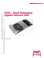
P602 – Quad Redundant
Gigabit Ethernet XMC
Configuration example
User Manual
®
P602 - Quad Redundant Gigabit Ethernet XMC
P602 - Quad Redundant Gigabit Ethernet XMC
The P602 is a Gigabit Ethernet XMC mezzanine card suitable for any XMC
compliant single-board computer or host carrier board in any type of bus system, i.e.
CPCI, VME or on any type of stand-alone SBC. Compared to PMC, the XMC
standard defines a different board-to-board connector for support of PCI Express®.
The four Ethernet channels on the P602 are provided by two Ethernet controllers
with two lines each. Each of the two XMC connectors supports one link with up to
four lanes. With a specific set-up the two lines inside each Ethernet controller can be
used as a redundant channel pair. In this mode one line is monitored by the other
line and the controller recognizes when an error occurs.
The P602 is typically suited as an extension for Windows® and Linux based
systems with a heavy demand for multiple and ultra-fast communication
requirements. As such it is used in high-bandwidth multi-channel communication
applications in networked appliances such as base stations, routers, switches,
gateways, residential gateway controllers, etc. Main target markets comprise
telecom, medical engineering and transportation.
For use in rugged environments the mezzanine module P602 is delivered with a
passive heat sink and is prepared for conformal coating. Equipped with Intel®
components that come exclusively from the Intel® Embedded Line, the P602 has a
guaranteed minimum standard availability of 5 years.
MEN Mikro Elektronik GmbH
20P602-00 E2 – 2012-03-02
2
Technical Data
Technical Data
Ethernet
• Four 10/100/1000Base-T Ethernet channels at front panel
• RJ45 connectors at front panel
• Two independent dual-port Ethernet controllers
- Fully integrated Gigabit Ethernet Media Access Controllers (MAC) and physical layer ports (PHY)
- 48kB per port on-chip packet buffer
- Full duplex and half duplex operation
• Ethernet controllers are connected by two PCIe® links with four lanes each
• Two LEDs per channel to signal LAN Link, Activity status and connection speed
(10/100/1000Base-T)
XMC Characteristics
• Compliant with XMC standard VITA 42.3-200x
• XMC connectors P15 and P16 assembled
Peripheral Connections
• Via front panel on four RJ45 connectors
PCI Express®
• Two links with four lanes each to connect local 1000Base-T Ethernet controllers
(1GB/s per channel in each direction)
• One link with four lanes on XMC connector P15 and one on P16
Electrical Specifications
• Isolation voltage: 1.5kV DC electrical isolation between isolated side and digital
side
• Supply voltage/power consumption:
- +5V or +12V (-5%/+5%), 1.4A typ. (+5V), 600mA typ. (+12V)
- +3.3V (-5%/+5%), 100mA typ.
• MTBF: 920,841h @ 40°C according to IEC/TR 62380 (RDF 2000)
Mechanical Specifications
• Dimensions: conforming to XMC standard VITA 42.0-200x
• Weight: 106 g (with heat sink)
MEN Mikro Elektronik GmbH
20P602-00 E2 – 2012-03-02
3
Technical Data
Environmental Specifications
• Temperature range (operation):
- 0..+55°C
- Industrial temperature range on request
- Airflow: min. 10m³/h
• Temperature range (storage): -40..+85°C
• Relative humidity (operation): max. 95% non-condensing
• Relative humidity (storage): max. 95% non-condensing
• Altitude: -300m to + 3,000m
• Shock: 15g/11ms
• Bump: 10g/16ms
• Vibration (sinusoidal): 2g/10..150Hz
• Conformal coating on request
Safety
• PCB manufactured with a flammability rating of 94V-0 by UL recognized manufacturers
EMC
• Tested according to EN 55022 (radio disturbance), IEC1000-4-2 (ESD) and
IEC1000-4-4 (burst)
Software Support
• Drivers from Intel® for Windows® and Linux
MEN Mikro Elektronik GmbH
20P602-00 E2 – 2012-03-02
4
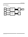
Block Diagram
Block Diagram
Electrical isolation
RJ45
RJ45
RJ45
RJ45
MEN Mikro Elektronik GmbH
20P602-00 E2 – 2012-03-02
Ethernet
10/100/1000Base‐T
Controller
Ethernet
10/100/1000Base‐T
Controller
PCIe x4
PCIe x4
XMC
Connector P15
Serial EEPROM
XMC
Connector P16
5
Product Safety
Product Safety
!
Electrostatic Discharge (ESD)
Computer boards and components contain electrostatic sensitive devices.
Electrostatic discharge (ESD) can damage components. To protect the board and
other components against damage from static electricity, you should follow some
precautions whenever you work on your computer.
• Power down and unplug your computer system when working on the inside.
• Hold components by the edges and try not to touch the IC chips, leads, or circuitry.
• Use a grounded wrist strap before handling computer components.
• Place components on a grounded antistatic pad or on the bag that came with the
component whenever the components are separated from the system.
• Store the board only in its original ESD-protected packaging. Retain the original
packaging in case you need to return the board to MEN for repair.
MEN Mikro Elektronik GmbH
20P602-00 E2 – 2012-03-02
6
About this Document
About this Document
This user manual is intended only for system developers and integrators, it is not intended for end users.
It describes the hardware functions of the board, connection of peripheral devices
and integration into a system. It also provides additional information for special
applications and configurations of the board.
The manual does not include detailed information on individual components (data
sheets etc.). A list of literature is given in the appendix.
History
Issue
Comments
Date
E1
First edition
2008-04-23
E2
Corrected Chapter 3.1 Power Supply on page 18
2012-03-02
Conventions
This sign marks important notes or warnings concerning the use of voltages which
can lead to serious damage to your health and also cause damage or destruction of
the component.
!
italics
bold
monospace
This sign marks important notes or warnings concerning proper functionality of the
product described in this document. You should read them in any case.
Folder, file and function names are printed in italics.
Bold type is used for emphasis.
A monospaced font type is used for hexadecimal numbers, listings, C function
descriptions or wherever appropriate. Hexadecimal numbers are preceded by "0x".
comment
Comments embedded into coding examples are shown in green color.
hyperlink
Hyperlinks are printed in blue color.
The globe will show you where hyperlinks lead directly to the Internet, so you can
look for the latest information online.
IRQ#
/IRQ
Signal names followed by "#" or preceded by a slash ("/") indicate that this signal is
either active low or that it becomes active at a falling edge.
in/out
Signal directions in signal mnemonics tables generally refer to the corresponding
board or component, "in" meaning "to the board or component", "out" meaning
"coming from it".
Vertical lines on the outer margin signal technical changes to the previous issue of
the document.
MEN Mikro Elektronik GmbH
20P602-00 E2 – 2012-03-02
7
About this Document
Legal Information
Changes
MEN Mikro Elektronik GmbH ("MEN") reserves the right to make changes without further notice to any products
herein.
Warranty, Guarantee, Liability
MEN makes no warranty, representation or guarantee of any kind regarding the suitability of its products for any
particular purpose, nor does MEN assume any liability arising out of the application or use of any product or
circuit, and specifically disclaims any and all liability, including, without limitation, consequential or incidental
damages. TO THE EXTENT APPLICABLE, SPECIFICALLY EXCLUDED ARE ANY IMPLIED
WARRANTIES ARISING BY OPERATION OF LAW, CUSTOM OR USAGE, INCLUDING WITHOUT
LIMITATION, THE IMPLIED WARRANTIES OF MERCHANTABILITY AND FITNESS FOR A
PARTICULAR PURPOSE OR USE. In no event shall MEN be liable for more than the contract price for the
products in question. If buyer does not notify MEN in writing within the foregoing warranty period, MEN shall
have no liability or obligation to buyer hereunder.
The publication is provided on the terms and understanding that:
1. MEN is not responsible for the results of any actions taken on the basis of information in the publication, nor
for any error in or omission from the publication; and
2. MEN is not engaged in rendering technical or other advice or services.
MEN expressly disclaims all and any liability and responsibility to any person, whether a reader of the publication
or not, in respect of anything, and of the consequences of anything, done or omitted to be done by any such person
in reliance, whether wholly or partially, on the whole or any part of the contents of the publication.
Conditions for Use, Field of Application
The correct function of MEN products in mission-critical and life-critical applications is limited to the
environmental specification given for each product in the technical user manual. The correct function of MEN
products under extended environmental conditions is limited to the individual requirement specification and
subsequent validation documents for each product for the applicable use case and has to be agreed upon in writing
by MEN and the customer. Should the customer purchase or use MEN products for any unintended or
unauthorized application, the customer shall indemnify and hold MEN and its officers, employees, subsidiaries,
affiliates, and distributors harmless against all claims, costs, damages, and expenses, and reasonable attorney fees
arising out of, directly or indirectly, any claim or personal injury or death associated with such unintended or
unauthorized use, even if such claim alleges that MEN was negligent regarding the design or manufacture of the
part. In no case is MEN liable for the correct function of the technical installation where MEN products are a part
of.
Trademarks
All products or services mentioned in this publication are identified by the trademarks, service marks, or product
names as designated by the companies which market those products. The trademarks and registered trademarks
are held by the companies producing them. Inquiries concerning such trademarks should be made directly to those
companies.
Conformity
MEN products are no ready-made products for end users. They are tested according to the standards given in the
Technical Data and thus enable you to achieve certification of the product according to the standards applicable in
your field of application.
MEN Mikro Elektronik GmbH
20P602-00 E2 – 2012-03-02
8
About this Document
RoHS
Since July 1, 2006 all MEN standard products comply with RoHS legislation.
Since January 2005 the SMD and manual soldering processes at MEN have already been completely lead-free.
Between June 2004 and June 30, 2006 MEN’s selected component suppliers have changed delivery to RoHScompliant parts. During this period any change and status was traceable through the MEN ERP system and the
boards gradually became RoHS-compliant.
WEEE Application
The WEEE directive does not apply to fixed industrial plants and tools. The compliance is the responsibility of the
company which puts the product on the market, as defined in the directive; components and sub-assemblies are
not subject to product compliance.
In other words: Since MEN does not deliver ready-made products to end users, the WEEE directive is not
applicable for MEN. Users are nevertheless recommended to properly recycle all electronic boards which have
passed their life cycle.
Nevertheless, MEN is registered as a manufacturer in Germany. The registration number can be provided on
request.
Copyright © 2012 MEN Mikro Elektronik GmbH. All rights reserved.
Germany
MEN Mikro Elektronik GmbH
Neuwieder Straße 3-7
90411 Nuremberg
Phone +49-911-99 33 5-0
Fax +49-911-99 33 5-901
E-mail [email protected]
www.men.de
MEN Mikro Elektronik GmbH
20P602-00 E2 – 2012-03-02
France
MEN Mikro Elektronik SA
18, rue René Cassin
ZA de la Châtelaine
74240 Gaillard
Phone +33 (0) 450-955-312
Fax +33 (0) 450-955-211
E-mail [email protected]
www.men-france.fr
USA
MEN Micro, Inc.
24 North Main Street
Ambler, PA 19002
Phone (215) 542-9575
Fax (215) 542-9577
E-mail [email protected]
www.menmicro.com
9
Contents
Contents
1 Getting Started . . . . . . . . . . . . . . . . . . . . . . . . . . . . . . . . . . . . . . . . . . . . . . . .
1.1 Map of the Board. . . . . . . . . . . . . . . . . . . . . . . . . . . . . . . . . . . . . . . . .
1.2 Integrating the Board into a System . . . . . . . . . . . . . . . . . . . . . . . . . .
1.3 Installing Driver Software . . . . . . . . . . . . . . . . . . . . . . . . . . . . . . . . . .
13
13
13
13
2 Connecting the XMC . . . . . . . . . . . . . . . . . . . . . . . . . . . . . . . . . . . . . . . . . . . 14
2.1 Peripheral Interfaces . . . . . . . . . . . . . . . . . . . . . . . . . . . . . . . . . . . . . . 14
2.2 Host PCI Interface . . . . . . . . . . . . . . . . . . . . . . . . . . . . . . . . . . . . . . . . 15
3 Functional Description . . . . . . . . . . . . . . . . . . . . . . . . . . . . . . . . . . . . . . . . . .
3.1 Power Supply. . . . . . . . . . . . . . . . . . . . . . . . . . . . . . . . . . . . . . . . . . . .
3.2 Ethernet Interfaces. . . . . . . . . . . . . . . . . . . . . . . . . . . . . . . . . . . . . . . .
3.2.1
Ethernet Controller . . . . . . . . . . . . . . . . . . . . . . . . . . . . . . . .
3.2.2
Thermal Considerations . . . . . . . . . . . . . . . . . . . . . . . . . . . .
18
18
18
18
19
4 Appendix . . . . . . . . . . . . . . . . . . . . . . . . . . . . . . . . . . . . . . . . . . . . . . . . . . . . . 20
4.1 Literature and Web Resources . . . . . . . . . . . . . . . . . . . . . . . . . . . . . . . 20
4.1.1
XMC . . . . . . . . . . . . . . . . . . . . . . . . . . . . . . . . . . . . . . . . . . . 20
4.1.2
PCI Express. . . . . . . . . . . . . . . . . . . . . . . . . . . . . . . . . . . . . . 20
4.2 Finding out the Board’s Article Number, Revision and Serial Number20
MEN Mikro Elektronik GmbH
20P602-00 E2 – 2012-03-02
10
Figures
Figure 1. Map of the board—front panel and top view . . . . . . . . . . . . . . . . . . . . 13
Figure 2. Labels giving the board’s article number, revision and serial number. 20
MEN Mikro Elektronik GmbH
20P602-00 E2 – 2012-03-02
11
Tables
Table 1.
Table 3.
Table 4.
Table 5.
Table 6.
Status LEDs of 8-pin RJ45 Ethernet 10/100/1000Base-T connectors
(LAN_A..LAN_D) . . . . . . . . . . . . . . . . . . . . . . . . . . . . . . . . . . . . . . . . 14
Pin assignment of 8-pin RJ45 Ethernet 10/100/1000Base-T connectors
(LAN_A..LAN_D) . . . . . . . . . . . . . . . . . . . . . . . . . . . . . . . . . . . . . . . . 14
Signal mnemonics of Ethernet 10/100/1000Base-T connectors. . . . . . 14
Pin assignment of 114-pin XMC connector P15 . . . . . . . . . . . . . . . . . 15
Pin assignment of 114-pin XMC connector P16 . . . . . . . . . . . . . . . . . 16
Signal mnemonics of 114-pin XMC connector . . . . . . . . . . . . . . . . . . 17
MEN Mikro Elektronik GmbH
12
Table 2.
20P602-00 E2 – 2012-03-02
Getting Started
1
Getting Started
This chapter gives an overview of the board and some hints for first installation in a
system.
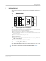
1.1
Map of the Board
Figure 1. Map of the board—front panel and top view
LEDs
Heat sink
LAN
D
LAN
C
LAN
B
Ethernet
Controller
Ethernet
Controller
LAN
A
XMC
Connector
P16
XMC
Connector
P15
LEDs
1.2
Integrating the Board into a System
You can use the following "check list" to install the XMC on a carrier board for the
first time and to test proper functioning of the board.
Power-down the system and remove the XMC carrier board.
Install the XMC in a suitable slot of the carrier board as described in the carrier
board’s user manual.
Insert the carrier board into the system again.
Power-up the system.
If there is a system crash or other abnormal behavior at start-up, check if the
XMC is plugged properly.
You can now install driver software for the P602.
1.3
Installing Driver Software
For a detailed description on how to install driver software please refer to the
respective documentation.
You can find any driver software available for download on MEN’s website.
MEN Mikro Elektronik GmbH
20P602-00 E2 – 2012-03-02
13
Connecting the XMC
2
Connecting the XMC
2.1
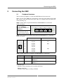
Peripheral Interfaces
You can connect peripherals via the four RJ45 Ethernet front connectors.
There are two status LEDs for each channel at the front panel which signal LAN
link, activity status and connection speed. They are assigned to the four connectors
in the following way.
Table 1. Status LEDs of 8-pin RJ45 Ethernet 10/100/1000Base-T connectors
(LAN_A..LAN_D)
Green LED:
On: Link 100Mbits/s
Off: Link with 10Mbits/s or
1000Mbits/s
Orange LED:
Blinks whenever there is
transmit or receive activity
LAN_A
LAN_B
LAN_C
LAN_D
LAN_A
LAN_B
LAN_D
8
1
8
1
8
1
8
1
LAN_C
Table 2. Pin assignment of 8-pin RJ45 Ethernet 10/100/1000Base-T connectors
(LAN_A..LAN_D)
1
8
1000Base-T
10/100Base-T
1
BI_DA+
TX+
2
BI_DA-
TX-
3
BI_DB+
RX+
4
BI_DC+
-
5
BI_DC-
-
6
BI_DB-
RX-
7
BI_DD+
-
8
BI_DD-
-
Table 3. Signal mnemonics of Ethernet 10/100/1000Base-T connectors
Signal
Direction
Function
BI_Dx+/-
in/out
Differential pairs of data lines for 1000Base-T
RX+/-
in
Differential pair of receive data lines for 10/
100Base-T
TX+/-
out
Differential pair of transmit data lines for 10/
100Base-T
Connector types:
• Modular 8/8-pin mounting jack according to FCC68
• Mating connector:
Modular 8/8-pin plug according to FCC68
MEN Mikro Elektronik GmbH
20P602-00 E2 – 2012-03-02
14
Connecting the XMC
2.2
Host PCI Interface
The P602 supports one PCI Express link with four lanes on each of the two XMC
connectors.
In the following you find the pin assignment of the 114-pin XMC plug connectors
P15 and P16:
Table 4. Pin assignment of 114-pin XMC connector P15
F E D C B A
1
2
F
E
D
C
B
A
1
VPWR
PET0n1
PET0p1
+3.3V
PET0n0
PET0p0
2
MRSTI#
GND
GND
-
GND
GND
3
VPWR
PET0n3
PET0p3
+3.3V
PET0n2
PET0p2
4
MRSTO#
GND
GND
TCK
GND
GND
5
VPWR
-
-
+3.3V
-
-
6
-
GND
GND
TMS
GND
GND
7
VPWR
-
-
+3.3V
-
-
8
-
GND
GND
TDI
GND
GND
9
VPWR
-
-
-
-
-
10
GA0
GND
GND
TDO
GND
GND
11
VPWR
PER0n1
PER0p1
-
PER0n0
PER0p0
GND
GND
GA1
GND
GND
12 MPRESENT#
19
13
VPWR
PER0n3
PER0p3
-
PER0n2
PER0p2
14
MSDA
GND
GND
GA2
GND
GND
15
VPWR
-
-
-
-
-
16
MSCL
GND
GND
MVMRO
GND
GND
17
-
-
-
-
-
-
18
-
GND
GND
-
GND
GND
19
-
-
WAKE0#
-
MEN Mikro Elektronik GmbH
20P602-00 E2 – 2012-03-02
REFCLK-0 REFCLK+0
15
Connecting the XMC
Table 5. Pin assignment of 114-pin XMC connector P16
F E D C B A
1
2
F
E
D
C
B
A
1
VPWR
PET1n1
PET1p1
+3.3V
PET1n0
PET1p0
2
MRSTI#
GND
GND
-
GND
GND
3
VPWR
PET1n3
PET1p3
+3.3V
PET1n2
PET1p2
4
MRSTO#
GND
GND
TCK
GND
GND
5
VPWR
-
-
+3.3V
-
-
6
-
GND
GND
TMS
GND
GND
7
VPWR
-
-
+3.3V
-
-
8
-
GND
GND
TDI
GND
GND
9
VPWR
-
-
-
-
-
10
GA0
GND
GND
TDO
GND
GND
11
VPWR
PER1n1
PER1p1
-
PER1n0
PER1p0
GND
GND
GA1
GND
GND
12 MPRESENT#
19
13
VPWR
PER1n3
PER1p3
-
PER1n2
PER1p2
14
MSDA
GND
GND
GA2
GND
GND
15
VPWR
-
-
-
-
-
16
MSCL
GND
GND
MVMRO
GND
GND
17
-
-
-
-
-
-
18
-
GND
GND
-
GND
GND
19
-
-
-
-
REFCLK-0 REFCLK+0
Connector:
• 114-pin XMC plug connector, e. g. SAMTEC :ASP105885-01
• Mating connector:
114-pin XMC receptacle connector
MEN Mikro Elektronik GmbH
20P602-00 E2 – 2012-03-02
16
Connecting the XMC
Table 6. Signal mnemonics of 114-pin XMC connector
Signal
Power
in
Variable power pins, +5V or 12V supply
voltage
+3.3V
in
+3.3V supply voltage
GND
-
Ground
in
PCI Express link 0, differential receive,
lanes 0..3
out
PCI Express link 0, differential transmit,
lanes 0..3
REFCLK+/-0
in
Differential reference clock
WAKE#
in
Reactivation of power rails and reference
clocks
in
PCI Express link 1, differential receive,
lanes 0..3
out
PCI Express link 1, differential transmit,
lanes 0..3
REFCLK+/-0
in
Differential reference clock
GA[0..2]
in
I2C channel select
MSCL
in
IPMI I2C serial clock
MPRESENT#
out
Module present
MRSTI#
in
XMC reset in
MRSTO#
out
XMC reset out
MSDA
in/out
IPMI I2C serial data
MVMRO
in
XMC write prohibit
PCI
PER1p/n[0..3]
Express
Link 1
PET1p/n[0..3]
MEN Mikro Elektronik GmbH
20P602-00 E2 – 2012-03-02
Function
VPWR
PCI
PER0p/n[0..3]
Express
Link 0
PET0p/n[0..3]
Other
Direction
17
Functional Description
3
Functional Description
3.1
Power Supply
The P602 is supplied via the carrier board. There are two supply voltages needed:
3.3V and VPWR. VPWR must be 5V or 12V.
The input currents at the P15 XMC connector are 1.4A (± 10%) with VPWR at 5V
or 0.6A (± 10%) with VPWR at 12V. 100mA (± 10%) are consumed at 3.3V.
A wide range switching power supply generates the Ethernet controller supply
voltages. These voltages have a value of 1.8V with a current of 2.2A (± 10%) and
1.1V with a current of 2.2A (± 10%).
3.2
Ethernet Interfaces
The P602 is equipped with two dual port gigabit Ethernet controllers and with a PCI
Express interface according to the XMC standard.
3.2.1
Ethernet Controller
The P602 is equipped with the Intel 82571EB Ethernet Controller. It is a single,
compact component with two fully integrated Gigabit Ethernet Media Access
Controllers (MAC) and physical layer ports (PHY). The device uses the PCI
Express architecture.
The Intel 82571EB provides a standard IEEE 802.3 Ethernet interface for
1000Base-T, 100Base-TX, and 10Base-T applications (802.3, 802.3u and 802.3ab).
The Gigabit Ethernet Controller with PCI Express architecture is designed for high
performance and low memory latency. The device is optimized to connect to a
system using four PCI express lanes (x4 PCI Express interface). Alternatively the
controller can use one PCI Express lane.
Wide internal data paths eliminate performance bottlenecks by efficiently handling
large address and data words.
A large 48kB per port on-chip packet buffer maintains superior performance. In
addition, using hardware acceleration, the controller offloads tasks from the host,
such as TCP/UDP/IP checksum calculations and TCP segmentation.
The controller can be used in redundancy mode for high availability, reliability and
safety.
In addition it provides a Serializer-Deserializer (SerDes) for optical fiber and
backplane applications as well as SMB and FML management ports for support of a
Board Management Controller (BMC).
MEN Mikro Elektronik GmbH
20P602-00 E2 – 2012-03-02
18
Functional Description
3.2.2
Thermal Considerations
The P602 Ethernet controllers are equipped with an extra heat sink which is
fastened on the top side with three screws.
!
Note: MEN gives no warranty on functionality and reliability of the P602 if you use
any other heat sink than that supplied by MEN. Please contact either MEN
directly or your local MEN sales office!
MEN Mikro Elektronik GmbH
20P602-00 E2 – 2012-03-02
19
Appendix
4
Appendix
4.1
Literature and Web Resources
• P602 data sheet with up-to-date information and documentation:
www.men.de
4.1.1
XMC
• XMC PCI Express Protocol Layer Standard
VITA 42.3-2006; June 2006
VMEbus International Trade Association
www.vita.com
• Standard for VITA 42.0 XMC
VITA 42.0-2008; December 2008
VMEbus International Trade Association
www.vita.com
4.1.2
PCI Express
• PCI Special Interest Group
www.pcisig.com
4.2
Finding out the Board’s Article Number, Revision and
Serial Number
MEN user documentation may describe several different models and/or hardware
revisions of the P602. You can find information on the article number, the board
revision and the serial number on two labels attached to the board.
• Article number: Gives the board’s family and model. This is also MEN’s ordering number. To be complete it must have 9 characters.
• Revision number: Gives the hardware revision of the board.
• Serial number: Unique identification assigned during production.
If you need support, you should communicate these numbers to MEN.
Figure 2. Labels giving the board’s article number, revision and serial number
Complete article number
15P602-00
00.00.00
Revision number
Serial number
MEN Mikro Elektronik GmbH
20P602-00 E2 – 2012-03-02
20