1
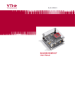
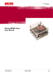
Doc.Nr. 82117600.01
SCC1300 GYRO-COMBO DEMO KIT
User Manual
SCC1300 GYRO-COMBO DEMO KIT
User Manual
TABLE OF CONTENTS
1 Introduction .........................................................................................................................3
2 Quick start for using the SCC1300 Demo Kit....................................................................3
3 Hardware..............................................................................................................................4
4 GUI software ........................................................................................................................4
4.1
Resetting GUI and µC ................................................................................................................8
4.2
Uninstalling the GUI and USB driver........................................................................................8
5 Advanced data logging.......................................................................................................9
6 USB interface board circuit diagram ...............................................................................11
7 USB interface board PWB layout .....................................................................................14
8 Troubleshooting ................................................................................................................15
8.1
Checking and setting correct USB driver Latency timer value ...........................................16
8.2
Duplicate serial COM port numbers.......................................................................................18
9 Document Revision History .............................................................................................19
10 Contact Information ..........................................................................................................19
VTI Technologies Oy
www.vti.fi
Doc.Nr. 82117600.01
2/19
Rev.0.1
SCC1300 GYRO-COMBO DEMO KIT
User Manual
1
Introduction
SCC1300 demo demonstrates the SCC1300 component functionality and the component key
properties. This document describes how to install the required software and how to use the
SCC1300 demo board and Graphical User Interface (GUI) software.
SCC1300 demo consists of:
• SCC1300 sensor soldered on a chip carrier PWB (see Figure 1 on next page)
• USB interface card (see Figure 1 on next page)
• USB cable
• GUI software running on PC
SCC1300 demo runs on recent Windows versions (Windows 7, Vista, XP and 2000) and it requires
USB connection for data transfer. Demo is powered from USB port. The SCC1300 demo is based
on the same USB hardware PCB as the SCA3000 Demo Kit, however please note that the original
SCA3000 Demo PCB is not compatible with SCC1300. The same USB driver can be used with all
demo kits provided by VTI Technologies.
2
Quick Start for Using the SCC1300 Demo Kit
Please follow the steps below:
1. Insert CD-ROM
2. Setup the hardware
- Connect the demo kit to PC's USB port
3. Install the USB driver, after the PC has found the device
- Let Windows to install the USB driver, if the driver is not found an executable
installer can be run from folder "CD-ROM\SCC1300 demo - Virtual Com
Port Drivers\”
- NOTICE, if you have already installed some other demo kit provided by VTI
Technologies, please check that the latency timer parameter is 5 ms. In case the
latency timer value is greater than 5 ms, the SCC1300 Demo Kit GUI will not work
(more detailed instructions in section 8)
4. Install the GUI software
- Install the GUI software by running the “setup.exe" from folder:
CD-ROM\SCC1300 demo – GUI Installer
- Do not change the installation destination
5. Start the GUI software
- From Start → Programs → SCC1300-USB-DEMO-VER-1.0 →
SCC1300-USB-DEMO-VER-1.0
When using the SCC1300 Demo Kit with GUI software:
• The Demo Kit should be connected to PC before the GUI software is started
• Exit the GUI software before unplugging the Demo Kit from PC
• After GUI software is stopped, the Demo Kit can be unplugged from PC (Demo Kit uses
virtual serial port driver, so it can not be found as a USB device).
During software start up, the firewall may alert that the demo software wants a network access.
The demo software can be operated without the network access (granting the network access will
not change the software operation).
VTI Technologies Oy
www.vti.fi
Doc.Nr. 82117600.01
3/19
Rev.0.1
SCC1300 GYRO-COMBO DEMO KIT
User Manual
3
Hardware
The SCC1300 Demo Kit USB interface board (black PWB) and SCC1300 PWB (green PWB) are
shown in Figure 1. The USB interface card converts the USB interface to SPI interface. SCC1300
sensor is soldered on PWB which is connected to interface board.
Green led: data transfer
SCC1300 sensor
Red led: demo
powered from USB
Demo reset
Figure 1. SCC1300 demo USB interface board and SCC1300 PWB.
4
GUI Software
SCC1300 Demo Kit is controlled via USB serial port by GUI software.
The GUI software has three different display modes. The SCC1300 sensor can be set to:
- Gyro & ACC: both gyro and accelerometer data is shown
- Gyro: only gyro data is shown
- ACC: only accelerometer data is shown
The three different GUI displays and start up screens are presented on the following pages.
VTI Technologies Oy
www.vti.fi
Doc.Nr. 82117600.01
4/19
Rev.0.1
SCC1300 GYRO-COMBO DEMO KIT
User Manual
Screen capture of the GUI is presented in
Figure 2.
1.
6.
2.
3.
7.
4.
8.
5.
9.
10.
11.
13.
12.
Figure 2. SCC1300 Demo Kit Graphical User Interface
Table 1. The numbered items in
Figure 2.
Item
1
2
3
4
5
6
7
8
9
10
11
12
13
VTI Technologies Oy
www.vti.fi
Description
Exit software, [Esc]-button also.
Pull down menu for acceleration [g] range
Manual acceleration range selections (Manual setting has to be selected
from Range [g] pulldown menu)
Pull down menu for angular rate [˚/s] range
Manual angular rate range selections (Manual setting has to be selected
from Range [˚/s] pulldown menu)
Current acceleration output value decimal display
Accelerometer scrolling display
Open / close the window extension with arrow button
Current angular rate output value decimal display
Gyro scrolling display
Pull down menu for GUI display mode
Display update delay
GUI software version number
Doc.Nr. 82117600.01
5/19
Rev.0.1
SCC1300 GYRO-COMBO DEMO KIT
User Manual
If more than one USB serial port devices
are connected to PC, user must select the
correct USB SERIAL PORT from pop-up
window (Figure 3). If user does not know
the correct USB serial port number, please
disconnect all other USB serial port
devices from PC and restart the GUI
software.
Figure 3. USB serial port selection pop-up window.
User needs to select the correct product
type from PRODUCT SELECTION pop-up
window (Figure 4). SCC1300-D02 is
selected by default.
Figure 4. Product selection pop-up window.
Gyro & ACC, continuously scrolling gyro
output and X, Y, Z accelerations, see
Figure 5. Angular rate is presented in [˚/s]
and acceleration in [g]. User can:
- change the acceleration scale
- select between angular rate sensor
measurement ranges 110[˚/s]/300[˚/s]
/Manual
- select between acceleration sensor
measurement ranges 2g/6g/Manual
Most of the actions/controls listed above
are in the extension part of the window,
which can be accessed by pressing the
arrow button (see
Figure 2 and Table 1).
Figure 5. Gyro & ACC display.
VTI Technologies Oy
www.vti.fi
Doc.Nr. 82117600.01
6/19
Rev.0.1
SCC1300 GYRO-COMBO DEMO KIT
User Manual
Gyro, continuously scrolling gyro
output. Angular rate is presented in
[˚/s].
Figure 6. Gyro display.
ACC, continuously scrolling X, Y and
Z outputs of the accelerometer.
Acceleration is presented in [g].
Figure 7. ACC display.
VTI Technologies Oy
www.vti.fi
Doc.Nr. 82117600.01
7/19
Rev.0.1
SCC1300 GYRO-COMBO DEMO KIT
User Manual
RESET DEMO initialises the GUI software.
The embedded MCU software version is
presented. Gyro & ACC display opens
after RESET by default.
Figure 8. Reset demo display.
4.1
Resetting GUI and µC
SCC1300 Demo Kit GUI software can be reinitialised by selecting the “Reset demo” display from
pull down menu, see Figure 8.
MCU can be reset by exiting from the GUI and then pressing the reset button (Figure 1) on USB
interface board.
4.2
Uninstalling the GUI and USB Driver
The GUI software and the USB driver (FTDI Serial Converter Driver) can be removed from
Windows Control Panel Add/Remove Programs. Please notice that removing the FTDI Serial
Converter Driver (USB driver) may affect on functionality of some other programs (such as other
demo kits provided by VTI Technologies).
VTI Technologies Oy
www.vti.fi
Doc.Nr. 82117600.01
8/19
Rev.0.1
SCC1300 GYRO-COMBO DEMO KIT
User Manual
5
Advanced data logging
Acceleration data can be saved from GUI software by pressing the “Save to file” button (
Figure 2). Data can be logged also by using the Windows HyperTerminal software and macro
language that is used to control the MCU of the SCC1300 Demo Kit.
Please notice that GUI software and Windows HyperTerminal software can not be open at the
same time. Follow the steps below to start the data logging:
1. Connect SCC1300 Demo Kit with USB cable to PC
2. Open GUI software to see the correct COM port number (SETUP display, see Error!
Reference source not found.). Windows Device Manager can also be used to find out the
COM port number.
3. Close the GUI software.
4. Open Windows HyperTerminal software from CD-ROM:
− “SCC1300_demo_HyperTerminal_connection.ht”, or
− see detailed serial communication settings in Table 2.
5. Press demo reset button (see Figure 1). SCC1300 Demo Kit sends an info text to
HyperTerminal (see Figure 9). If the HyperTerminal software is unable to connect the
SCC1300 Demo Kit or the info text does not appear,
,
- Press disconnect
- change the COM port number to correct from port properties
,
,
- press connect
- press reset button on SCC1300 Demo Kit.
until info text appears to HyperTerminal screen (see Figure 9).
6. After the info text appears on HyperTerminal, send the wanted macro text file, such as
“SCC1300_data_logger.txt” from CD-ROM (“Transfer” pull down menu → “Send Text
File…” → browse for
SCC1300_data_logger_macro.txt)
7. The text file is a macro that runs in an endless loop. The macro sends angular rate and 3axis acceleration data in hex format to HyperTerminal (see Figure 10). Example of data
format:
0x0025,0x004c,0x0008,0x0a1c,G-X-Y-Z
where “0x” indicates for hex format, and “G-Z-Y-X” the axis order.
8. The data can be stored by capturing the data in to file:
“Transfer” pull down menu → “Capture Text…” → save captured data into wanted file and
folder.
9. Data capturing can be stopped from:
“Transfer” pull down menu → “Capture Text…” → “Stop”
Macro language is used to control the SCC1300 DEMO KIT. It can be also used to configure the
SCC1300 sensor. For more detailed information of macro language, please refer to “SCA3000
DEMO KIT macro language description 8259200”.
VTI Technologies Oy
www.vti.fi
Doc.Nr. 82117600.01
9/19
Rev.0.1
SCC1300 GYRO-COMBO DEMO KIT
User Manual
Connection properties
2. Connect
1. Select COM port
Figure 9. Windows HyperTerminal with SCC1300 demo info text.
If the pre-configured HyperTerminal connection is not available (the CD-ROM), the HyperTerminal
connection can be opened also from:
→ Start → Programs → Accessories → Communications → HyperTerminal
The communication settings are presented in Table 2 below
Table 2. SCC1300 Demo Kit serial communication settings.
Parameter
Bits per second
Data bits
Parity
Stop bits
Flow control
Value
230400
8
None
1
None
The correct COM port number depends on the PC and USB port used.
Figure 10. SCC1300 demo output during data logging.
VTI Technologies Oy
www.vti.fi
Doc.Nr. 82117600.01
10/19
Rev.0.1
SCC1300 GYRO-COMBO DEMO KIT
User Manual
6
USB Interface Board Circuit Diagram
SCC1300 demo USB interface board circuit diagram is presented in following pages.
Figure 11. SCC1300 Demo Kit USB interface board circuit diagram (sheet USB).
VTI Technologies Oy
www.vti.fi
Doc.Nr. 82117600.01
11/19
Rev.0.1
SCC1300 GYRO-COMBO DEMO KIT
User Manual
Figure 12. SCC1300 Demo Kit USB interface board circuit diagram (sheet MCU).
VTI Technologies Oy
www.vti.fi
Doc.Nr. 82117600.01
12/19
Rev.0.1
SCC1300 GYRO-COMBO DEMO KIT
User Manual
Figure 13. SCC1300 Demo Kit USB interface board circuit diagram (sheet power, resistor R34 is 0
ohm instead of 470 ohm described in the schematics).
VTI Technologies Oy
www.vti.fi
Doc.Nr. 82117600.01
13/19
Rev.0.1
SCC1300 GYRO-COMBO DEMO KIT
User Manual
7
USB interface board PWB layout
SCC1300 Demo Kit USB interface board PWB layout and silkscreen is presented below.
Figure 14. SCC1300 Demo Kit USB interface board PWB layout.
Figure 15. SCC1300 Demo Kit USB interface board silkscreen.
VTI Technologies Oy
www.vti.fi
Doc.Nr. 82117600.01
14/19
Rev.0.1
SCC1300 GYRO-COMBO DEMO KIT
User Manual
8
Troubleshooting
Due to many PC environments, the interoperability can be limited. The SCC1300 Demo Kit has
been tested with DELL laptops (Latitude D600, D610, D620, D410) and desktop PCs with Win2000
WinXP, Vista and Windows 7 operating systems. If the SCC1300 Demo Kit does not work properly
or its operation is limited, the following items may help to sort the problems out:
1. Stop the GUI software, press the reset button program on demo USB interface board (see
Figure 1), re-start the GUI again.
2. SCC1300 demo may not work properly if your PC has multiple USB serial port devices
installed. Please remove all other USB serial port devices (including other VTI demos).
3. Close Windows HyperTerminal software, if you have used it.
4. If the GUI interface starts, but data is not scrolling in the window, check that USB driver
LATENCY TIMER parameter is 5ms, please see details in section 8.1
5. Some times other LabView based software do not allow the demo kit GUI software
execution, please try to install the SCC1300 demo kit to another PC or remove other
LabView based software
6. If the PC is unable to find the demo kit serial port, try another USB port. Also, please check
that there are not duplicate serial COM port numbers, more details in section 8.2.
7. Test the demo with another USB cable.
8. Check that the communication between the demo kit and the PC works:
• Open HyperTerminal connection to the demo (see section 5)
• Press demo reset button (see Figure 1)
• see if the info text appears on the screen (see Figure 9)
→ if the info text is transmitted, the communication between the demo kit and PC is ok
VTI Technologies Oy
www.vti.fi
Doc.Nr. 82117600.01
15/19
Rev.0.1
SCC1300 GYRO-COMBO DEMO KIT
User Manual
8.1
Checking and Setting Correct USB Driver Latency Timer Value
The FTDI USB Virtual Serial Com Port driver is delivered with the SCC1300 demo kit and the same
driver version can be also downloaded from VTI's website.
In order to modify the driver's Latency timer value, please plug the demo USB cable in to PC and
follow the steps (and screen captures) below:
1. Open control panel and select “SYSTEM”
2. Select “DEVICE MANAGER” from “HARDWARE” tab
3. Select “USB SERIAL PORT” from the list, right mouse click and select
“PROPERTIES"
4. Select “ADVANVED” from the USB Serial port Properties
5. Set the “LATENCY TIMER” to 5 ms (the 16ms default value is too slow for SCC1300
Demo Kit).
6. Press “OK” to all windows.
7. Restart the GUI software.
Start → Control panel
1.
2.
VTI Technologies Oy
www.vti.fi
Doc.Nr. 82117600.01
16/19
Rev.0.1
SCC1300 GYRO-COMBO DEMO KIT
User Manual
4.
3.
5.
VTI Technologies Oy
www.vti.fi
Doc.Nr. 82117600.01
17/19
Rev.0.1
SCC1300 GYRO-COMBO DEMO KIT
User Manual
8.2
Duplicate Serial COM Port Numbers
Some PCs assign duplicate COM port numbers for virtual com port devices. If the PC assigns a
COM port number for demo kit that is already reserved by another device, the demo kit will not
work properly (see Figure 16).
COM port numbers can be seen from Computer Management (Device Manager), see section 8.1
for instructions on opening the Device Manager.
PC installs the
demo kit on
same COM port
number as
another device
After changing
the demo to
another USB port
(different slot),
there are no
duplicate COM
port numbers
Figure 16. PC has assigned duplicate COM port numbers for two devices (LEFT), after
changing the USB port there are no duplicate COM port numbers (RIGHT).
VTI Technologies Oy
www.vti.fi
Doc.Nr. 82117600.01
18/19
Rev.0.1
SCC1300 GYRO-COMBO DEMO KIT
User Manual
9
Document Revision History
Version
Date
Change Description
0.1
08.12.2009
Initial release
10 Contact Information
Finland
(head office)
VTI Technologies Oy
P.O. Box 27
Myllynkivenkuja 6
FI-01621 Vantaa
Finland
Tel. +358 9 879 181
Fax +358 9 8791 8791
E-mail: [email protected]
Germany
VTI Technologies Oy
Branch Office Frankfurt
Rennbahnstrasse 72-74
D-60528 Frankfurt am Main,
Germany
Tel. +49 69 6786 880
Fax +49 69 6786 8829
E-mail: [email protected]
Japan
VTI Technologies Oy
Tokyo Office
Tokyo-to, Minato-ku 2-7-16
Bureau Toranomon 401
105-0001
Japan
Tel. +81 3 6277 6618
Fax +81 3 6277 6619
E-mail: [email protected]
China
VTI Technologies Shanghai Office
6th floor, Room 618
780 Cailun Lu
Pudong New Area
201203 Shanghai
P.R. China
Tel. +86 21 5132 0417
Fax +86 21 513 20 416
E-mail: [email protected]
VTI Technologies Oy
www.vti.fi
Doc.Nr. 82117600.01
USA
VTI Technologies, Inc.
70 South Lake Ave., 10th Floor
Pasadena, CA 91101
USA
Tel. +1 626 463 7011
Fax +1 626 463 7013
E-mail: [email protected]
To find out your local sales
representative visit www.vti.fi
19/19
Rev.0.1
Mouser Electronics
Authorized Distributor
Click to View Pricing, Inventory, Delivery & Lifecycle Information:
Murata:
SCC1300-D02DEMO SCC1300-D04DEMO SCC1300-D02 PWB