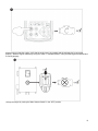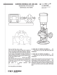
1
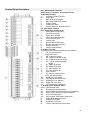
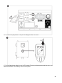
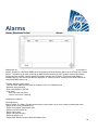
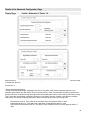
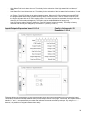
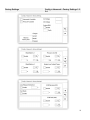
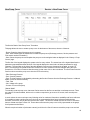
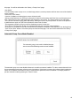
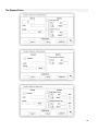
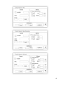
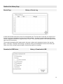
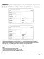
- 0-10V: Theoretical calibration with 0-10V sensor. Simply enter a value in the system pressure unit for 0V and
another value for 10V. Click on the “Apply” button to confirm the calibration. The resulting measured pressure is
shown in the lower right corner of the “Sensor” box. Make sure the dipswitch package right below the “T” terminals
is set to “0-10V” for that particular sensor (refer to the drawing). The switches are labelled and are each linked to
one analog input, in this case “1 or 2”. *Important Note: A set of jumpers is also associated with each analog input.
MAKE SURE THE CONTROLLER IS COMPLETELY POWERED OFF BEFORE MOVING A JUMPER. THIS
INCLUDES REMOVING THE AC AND DC POWER. The jumper can be placed on “5Vdc”, “12Vdc” and “Vaux” and
represents the powered DC value of the sensor. The factory pre-set position is “5Vdc”. If an installed sensor has a
power value of “5Vdc”, then the “0-10V” theoretical calibration must be calculated accordingly. Please contact
manufacturer for more information.
- 4-20mA: Theoretical calibration with 4-20mA sensor. Simply enter a value in the system pressure unit for 4mA and
another value for 20mA. The procedure explained above also applies in this case.
-Field Calibration: This is the factory pre-set method and the only one that is an actual calibration. Selecting this
calibration method will generate the Calibration box situated in the lowest part of the sensor page. It is very
important that the same care is used when selecting the appropriate dipswitch setting and jumper position. Please
refer to the “0-10V” section above.
1.Two actual points (low and high) are required
2. Set the lowest point (usually 0).
3. Press the left read button
4. Press the left rectangle text field and enter the value read on the external calibrated gauge.
5. Set a high point (usually the highest possible value will create the best calibration).
6. Press the right read button
7. Press the right rectangle text field and enter the value read on the external calibrated gauge.
8. Press the calculate button to finish the calibration. If the settings are incorrect, the calculate button will remain red
and if correct, the button will turn blue. The resulting measured value is shown in the lower right corner of the
“Sensor” box.
- On/Off: Use the input with a dry contact sensor, for example a float switch. The only parameter to set for this
method is the NO/NC buttons, effectively selecting between a normally open and a normally close switch. Click on
the “Apply” button to confirm the calibration.
The Alarms Section: (“Level 1” security)
The “DRY” button can enable or disable the “Dry Contact Input” on the IO board. There are two modes when
enabled, either “Normally open, NO” or “Normally close, NC”. Each mode is represented by the standard NO/NC
symbols.
- Enable/Disable the corresponding alarm/warning condition by pressing the square button
- Alarm Bell Icon: Activates the bell when the condition occurs.
- Alarm Icon: If selected, the occurring condition will be an alarm. If unselected, it will be a simple warning.
-RESET: Value at which the condition will go from the “ACTIVE” state to the “OCCURRED” state.
-SET: Value at which the system will activate the corresponding condition.
47