1
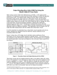
2191A
± 40 V DC BIAS ADAPTER
MODEL 2191A
Instruction Manual
PN# 2191A-900-01
Publication Date: September 2013
REV. B
NOTE: This User’s Manual was as current as possible when this product was manufactured. However,
products are constantly being updated and improved. To ensure you have the latest documentation, refer
to www.tegam.com
10 TEGAM WAY • GENEVA, OHIO 44041 • 440-466-6100 • FAX 440-466-6110
• [email protected]
TABLE OF CONTENTS
TABLE OF CONTENTS
1. INSTRUMENT DESCRIPTION
Description ........................................................... 1-1
Performance Characteristics ................................... 1-1
Unpacking and Inspection ...................................... 2-1
List of Items Furnished .......................................... 1-2
2. PREPARATION FOR USE AND INSTALLATION
Connections to DUT ............................................... 2-1
OPEN/SHORT Correction ........................................ 3-1
Figure 1a, 1b: OPEN/SHORT Correction ................ 3-2
3. OPERATING INSTRUCTIONS
Measurement Method ............................................ 3-1
Figure 2: Connection Diagram ............................. 3-2
Safe Discharge Operating Procedure ........................ 3-2
Figure 3: Block Diagram ..................................... 3-4
Figure 4: Front and Rear Panel ............................ 3-5
4. MAINTENANCE & SERVICE INFORMATION
Inspection ............................................................ 4-1
Cleaning .............................................................. 4-1
Preparation for Shipment ....................................... 4-1
Overhaul Instructions ............................................ 4-1
Preparation for Repair Service................................. 4-2
Expedite Repair and Calibration Form ...................... 4-3
Warranty.............................................................. 4-4
10 TEGAM WAY • GENEVA, OHIO 44041 • 440-466-6100 • FAX 440-466-6110
• [email protected]
INSTRUMENT DESCRIPTION
SECTION 1
INSTRUMENT DESCRIPTION
1.1 Description
The TEGAM Model 2191A DC Bias Adapter is an electronic
instrument designed as an accessory to expand the
performance of TEGAM brand, or other standard LCR meters.
When connected properly, the 2191A allows the user to
apply up to ± 40 VDC to bias a device under test (DUT), like
a capacitor, or provide up to 40 VDC of input protection to
the LCR meter when used to test energized components like
batteries.
The 2191A is a passive device requiring no battery, or
external power to operate.
The 2191A has eight BNC I/O connectors that allow it to be
connected inline between the user's LCR meter and the DUT
via four 6” BNC cables (provided), and a set of four-wire test
leads (user supplied). The connectors are labeled: HFORCE
(High Current/Drive), HSENSE (High Voltage/Sense), LSENSE
(Low Voltage/Sense), and LFORCE (Low Current/Drive).
A ninth BNC connector, labeled "EXT DC BIAS", is provided
as a bias voltage input where up to ± 40 VDC may be
applied.
1.2 Performance Characteristics
External DC Bias voltage: Up to ± 40 VDC
Frequency Range: 100 Hz to 1 MHz
Current Limiting Resistor: 4 kΩ ± 5 %
10 TEGAM WAY • GENEVA, OHIO 44041 • 440-466-6100 • FAX 440-466-6110
• [email protected]
1-1
INSTRUMENT DESCRIPTION
Dimensions: 140 mm (5.5”) x 190.5 mm (7.5”) x 50.8 mm
(2”)
Weight: 1.76 lb (0.8 kg).
Environmental: 0 to 55 °C, ≤ 95% RH non-condensing.
Capacitive Component Charge Time: The time required for a
capacitive component to charge through the input resistance
is calculated using the following formula:
T(s) = 1.6 + (0.02 x C) s, where C is the capacitance of the DUT in µF.
1.3 Unpacking and Inspection
Upon receipt, the 2191A should be carefully unpacked and
removed from the shipping container. Separate the unit from
the packing material and inspect the instrument for any
external damage. If any components appear to be damaged
or missing, contact TEGAM immediately at 800-666-1010 or
[email protected] for corrective action.
1.4 List of Items Furnished
1 each Model 2191A
1 each Instruction Manual (PN# 2191A-900-01)
4 each six inch BNC male to BNC male cables (PN# CA-115-6)
10 TEGAM WAY • GENEVA, OHIO 44041 • 440-466-6100 • FAX 440-466-6110
• [email protected]
1-2
PREPARATION FOR USE AND INSTALLATION
SECTION 2
PREPARATION FOR USE AND INSTALLATION
Connections to DUT
Four BNC cables are provided to connect the 2191A to your
LCR Meter. These four cables are connected between the
input connectors of your LCR meter, and the end of the
2191A labeled "LCR METER CONNECTION". Your test leads or
kelvin probes are then attached accordingly to the four BNC
connectors on the other end of the 2191A labeled "TEST
SAMPLE / FIXTURE". Please note that BNC connectors at both
ends of the 2191A include convenient labeling for HFORCE,
HSENSE, LSENSE, and LFORCE. The DC Bias terminal may be
connected to an external voltage source to apply dc bias
voltage to the DUT. No button or switch is present on the
instrument.
OPEN/SHORT Correction
The 2191A Bias Adapter has inherent residual resistance,
stray capacitance, and residual inductance. If not properly
compensated, measurement accuracy may be degraded.
Once the 2191A and test probes are connected to the LCR
meter, the user must complete an "OPEN" and "SHORT"
compensation to cancel these residuals and minimize
measurement error.
The OPEN circuit zero correction procedure compensates for
stray
capacitance
and
conductance
between
test
leads/fixture. Make sure that the test leads are in the open
state as shown in figure 1a before performing the OPEN
circuit zero correction procedure.
10 TEGAM WAY • GENEVA, OHIO 44041 • 440-466-6100 • FAX 440-466-6110
• [email protected]
2-1
PREPARATION FOR USE AND INSTALLATION
The SHORT circuit zero correction procedure compensates for
residual resistance and inductance in the test leads/fixture.
Make sure that the test leads are shorted as shown in figure
1b, before performing the SHORT circuit zero correction
procedure.
Please refer to the LCR meter's user manual to find the
specific lead compensation procedure and execute it.
WARNING
DO NOT CONNECT THE BIAS
CORRECTION IS IN PROGRESS.
Figure 1a: Open Correction
VOLTAGE
WHILE
Figure 1b: Short Correction
10 TEGAM WAY • GENEVA, OHIO 44041 • 440-466-6100 • FAX 440-466-6110
• [email protected]
2-2
OPERATING INSTRUCTIONS
SECTION 3
OPERATING INSTRUCTIONS
Measurement Method
For safety reason, follow the following procedure carefully
when a DC Bias voltage needs to be applied to the DUT.
1. Perform open and short circuit compensation.
2. Connect the DUT (capacitor).
3. Set the output voltage of the external DC bias supply to 0
V. Increase the output voltage progressively to reach the
required value.
4. Measure the required parameters (capacitance, dissipation
factor etc.) of the DUT.
5. Gradually decrease the voltage of the external DC bias
supply until it reaches 0 V.
6. Remove the DUT.
WARNINGS
DO NOT SHORT THE HIGH AND LOW TERMINALS WHEN THE
VOLTAGE SOURCE IS TURNED ON.
FOR HIGH VALUE CAPACITORS, ALLOW SUFFICIENT TIME
FOR THE CAPACITOR TO CHARGE TO THE APPLIED
VOLTAGE.
WHEN A POSITIVE BIAS VOLTAGE IS USED, THE POSITIVE
TERMINAL OF AN ELECTROLYTIC CAPACITOR MUST BE
CONNECTED TO THE INSTRUMENTS HIGH TERMINAL.
WHEN A NEGATIVE BIAS VOLTAGE IS USED, CONNECT AN
ELECTROLYTIC CAPACITOR'S NEGATIVE TERMINAL TO THE
INSTRUMENT'S HIGH TERMINAL.
DO NOT TOUCH THE CONNECTORS WHEN THEY ARE
CONNECTED TO EXTERNAL CIRCUITS. LETHAL VOLTAGES
MAY BE PRESENT.
DO NOT OPERATE THIS INSTRUMENT IN PRESENCE OF
FLAMMABLE GASSES OR FUMES.
10 TEGAM WAY • GENEVA, OHIO 44041 • 440-466-6100 • FAX 440-466-6110
• [email protected]
3-1
OPERATING INSTRUCTIONS
Please refer to the following diagram for connections.
Figure 2: Connection Diagram
3.1 Safe Discharge Operating Procedure
WARNING
FAILURE TO PROPERLY DISCHARGE THE INTERNAL
DC BLOCKING CAPACITOR MAY RESULT IN SEVERE
DAMAGE TO THE LCR METER’S INPUT PROTECTION
AND MEASUREMENT CIRCUITS.
The 2191A’s has an internal DC blocking capacitor. When a DC
bias voltage is applied, this DC blocking capacitor will charge
to nearly the same voltage. If the test leads or test adapter
10 TEGAM WAY • GENEVA, OHIO 44041 • 440-466-6100 • FAX 440-466-6110
• [email protected]
3-2
OPERATING INSTRUCTIONS
connections are shorted, the stored energy within this DC
blocking capacitor may source currents through the input
protection and measurement circuits of the LCR meter, with
little current limitation. However, using the internal current
limiting feature designed into the EXT DC BIAS connection, the
stored energy may be safely discharged. One of the
procedures described below is required to protect the
measurement system. Likewise, either procedure must be
followed for each and any new device under test (DUT). That
is, if a new DUT is to be measured, discharge the 2191A.
The procedures described below can be used whether a
capacitive device under test (DUT) is connected or not.
However, if a battery is the DUT, it must be removed prior to
discharging the system.
NOTE: At no time should a charged capacitor or capacitive
device be connected to the 2191A. Discharge any capacitors
before any measurements. Likewise, a battery should not be
connected to the 2191A until a DC bias voltage, equivalent to
the battery’s terminal voltage, has been applied. As stated
above, severe damage may occur to protection and
measurement circuits of the LCR meter.
3.2 Procedure for a DC Supply that does not present low
impedance when in the off state
1. Once a DC bias voltage has been applied, remove the cable
from the EXT DC BIAS BNC connector. Use a BNC shorting
cap (e.g.: Pomona P/N 5085) and place it on the EXT DC
BIAS BNC connector, or
2. With the power supply cable connected at the DC Bias
BNC, remove your connection at the DC supply and short
the ends of that cable.
3. Allow 30 seconds for the internal DC blocking capacitor to
discharge.
4. If verification is required that the stored energy (voltage) is
dissipated, use a voltmeter and measure (on the TEST
SAMPLE / FIXTURE side of 2191A) between the center pin
10 TEGAM WAY • GENEVA, OHIO 44041 • 440-466-6100 • FAX 440-466-6110
• [email protected]
3-3
OPERATING INSTRUCTIONS
of the HFORCE BNC and shell of the LFORCE BNC. A
measurement of nearly zero volts should be observed.
3.3 Procedure for a DC Supply that presents low impedance
when in the off state
1. Once a DC bias voltage has been applied, either turn off
the power supply, or disable the output if the supply has
this feature. Power supplies may offer a front panel switch
or other mechanism that will disable the output, presenting
a low impedance at its connecting terminals.
2. Allow 30 seconds for the internal DC blocking capacitor to
discharge.
3. If verification is required that the stored energy (voltage) is
dissipated, use a voltmeter and measure (on the TEST
SAMPLE / FIXTURE side of 2191A) between the center pin
of the HFORCE BNC and shell of the LFORCE BNC. A
measurement of nearly zero volts should be observed.
Figure 3: Block Diagram
10 TEGAM WAY • GENEVA, OHIO 44041 • 440-466-6100 • FAX 440-466-6110
• [email protected]
3-4
OPERATING INSTRUCTIONS
Figure 4: Front and Rear Panel
10 TEGAM WAY • GENEVA, OHIO 44041 • 440-466-6100 • FAX 440-466-6110
• [email protected]
3-5
SERVICE INFORMATION
SECTION 4
MAINTENANCE & SERVICE INFORMATION
4.1 Inspection
The 2191A and its interface cables should be inspected
periodically to insure they are in good working condition.
4.2 Cleaning
The instrument should be cleaned periodically, as is
necessary, using mild soap and a damp cloth both followed
by second damp rinsing cloth. DO NOT use alcohol, solvents,
or harsh chemicals to clean.
4.3 Preparation for Shipment
The original shipping carton is not reusable.
The Model 2191A requires no special covering, preservation
or special cradles. Packaging must provide sufficient resilient
material, in accordance with standard packaging practices, to
prevent excessive shock during shipment.
4.4 Overhaul Instructions
The 2191A requires no periodic overhaul, other than routine
cleaning and inspection of cables.
10 TEGAM WAY • GENEVA, OHIO 44041 • 440-466-6100 • FAX 440-466-6110
• [email protected]
4-1
SERVICE INFORMATION
Preparation for Repair Service
If damage, or a malfunction occurs that requires repair
service, contact TEGAM customer service to obtain an RMA,
(Returned Material Authorization), number. TEGAM customer
service may be reached via the TEGAM website,
www.tegam.com or by calling 440.466.6100 (All Locations)
OR 800.666.1010 (United States Only).
The RMA number is unique to your instrument. Assigning one
prior to returning the instrument will help insure timely and
accurate service to your instrument.
In addition, your detailed written description of the problem,
attached to the instrument prior to shipment, will help to
reduce repair time. When describing the problem, please
consider such details as measurement range, test conditions
that may cause the symptoms, or any other observations
that you have that might assist in the troubleshooting effort.
10 TEGAM WAY • GENEVA, OHIO 44041 • 440-466-6100 • FAX 440-466-6110
• [email protected]
4-2
SERVICE INFORMATION
Expedite Repair & Calibration Form
Use this form to provide additional repair information and
service instructions. The Completion of this form and
including it with your instrument will expedite the processing
and repair process.
RMA#:
Instrument
Model #:
Company:
Phone
Number:
Serial Number:
Technical
Contact:
Additional
Contact Info:
Repair Instructions:
Evaluation
Repair & Calibration
Calibration Only
Z540
Repair Only
Detailed Symptoms:
Include information such as measurement range, instrument
settings, type of components being tested, is the problem
intermittent? When is the problem most frequent?, has
anything changed with the application since the last time the
instrument was used?, etc.
10 TEGAM WAY • GENEVA, OHIO 44041 • 440-466-6100 • FAX 440-466-6110
• [email protected]
4-3
SERVICE INFORMATION
Warranty
TEGAM, Inc. warrants this product to be free from defects in
material and workmanship for a period of one year from the
date of shipment. During this warranty period, if a product
proves to be defective, TEGAM Inc., at its option, will either
repair the defective product without charge for parts and
labor, or exchange any product that proves to be defective.
In order to exercise this warranty, TEGAM, Inc., must be
notified of the defective product before the expiration of the
warranty period. The customer shall be responsible for
packaging and shipping the product to the designated
TEGAM service center with shipping charges prepaid. TEGAM
Inc. shall pay for the return of the product to the customer if
the shipment is to a location within the country in which the
TEGAM service center is located. The customer shall be
responsible for paying all shipping, duties, taxes, and
additional costs if the product is transported to any other
locations. Repaired products are warranted for the remaining
balance of the original warranty, or 90 days, whichever
period is longer.
Warranty Limitations
The TEGAM, Inc. warranty does not apply to defects resulting
from unauthorized modification or misuse of the product or
any part. This warranty does not apply to fuses, batteries, or
damage to the instrument caused by battery leakage.
The foregoing warranty of TEGAM is in lieu of all other
warranties, expressed or implied. TEGAM specifically
disclaims any implied warranties of merchantability or fitness
for a particular purpose. In no event will TEGAM be liable for
special or consequential damages. Purchaser’s sole and
exclusive remedy in the event any item fails to comply with
the foregoing express warranty of TEGAM shall be to return
the item to TEGAM; shipping charges prepaid and at the
option of TEGAM obtain a replacement item or a refund of
the purchase price.
10 TEGAM WAY • GENEVA, OHIO 44041 • 440-466-6100 • FAX 440-466-6110
• [email protected]
4-4
SERVICE INFORMATION
Contact Information
TEGAM INC.
10, TEGAM WAY
GENEVA, OHIO 44041
CAGE Code: 49374
WEB: http://www.tegam.com
10 TEGAM WAY • GENEVA, OHIO 44041 • 440-466-6100 • FAX 440-466-6110
• [email protected]
4-5