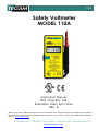
1
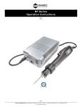
110A
Safety Voltmeter
MODEL 110A
Instruction Manual
PN# 110A-901-01E
Publication Date: April 2014
REV. E
NOTE: This User’s Manual was as current as possible when this product was manufactured. However,
products are constantly being updated and improved. To ensure you have the latest documentation,
refer to www.tegam.com
10 TEGAM WAY • GENEVA, OHIO 44041 • 440-466-6100 • FAX 440-466-6110
• [email protected]
110A
10 TEGAM WAY • GENEVA, OHIO 44041 • 440-466-6100 • FAX 440-466-6110
• [email protected]
TABLE OF CONTENTS
TABLE OF CONTENTS
1 INSTRUMENT DESCRIPTION
INTRODUCTION .......................................................1-1
SPECIFICATIONS ......................................................1-2
ACCESSORIES SHEET ................................................. 1-4
2 PREPARATION FOR USE
UNPACKING AND INSPECTION ..................................2-1
PREPARATION FOR USE .............................................2-1
OPERATION.............................................................2-1
OPERATING CONDITIONS .........................................2-2
FRONT PANEL ..........................................................2-3
3 SAFETY AND MAINTENANCE
SAFETY SYMBOLS AND TERMS ..................................3-1
OPTIONAL SAFETY TESTS .........................................3-3
MAINTENANCE INFORMATION ...................................3-5
Test Lead Replacement ......................................3-5
FUNCTIONALITY CHECKS ..........................................3-6
PERFORMANCE VERIFICATION ..................................3-7
BATTERY INSTALLATION/REPLACEMENT .....................3-8
CLEANING INSTRUCTIONS ........................................3-9
4 SERVICE INFORMATION
PREPARATION FOR CALIBRATION OR REPAIR .............4-1
EXPEDITE REPAIR & CALIBRATION FORM ...................4-2
WARRANTY .............................................................4-3
10 TEGAM WAY • GENEVA, OHIO 44041 • 440-466-6100 • FAX 440-466-6110
• [email protected]
INSTRUMENT DESCRIPTION
SECTION 1
INSTRUMENT DESCRIPTION
INTRODUCTION
The Model 110A Safety Voltmeter is the only single switch,
single range, digital voltmeter that automatically measures
AC & DC volts to 1000 V for voltage troubleshooting, line
clearing, lock out/tag out procedures and anywhere
hazardous voltages may be present. The 110A has a 1 MΩ
current limiting resistor in each lead to protect the user
against arc-flash potential.
Model 110A maintains a cULus approval and meets Category
IV 600 V and Category III 1000 V Overvoltage protection
under IEC-61010-1.
10 TEGAM WAY • GENEVA, OHIO 44041 • 440-466-6100 • FAX 440-466-6110
• [email protected]
1-1
INSTRUMENT DESCRIPTION
SPECIFICATIONS
FUNCTIONS: VDC/VAC, with automatic selection. When both DC
and AC input voltages are present, the voltage type with the higher
magnitude is selected and displayed.
RANGES: ±1000 VDC. 1000 VAC (45-500 Hz, average responding,
calibrated in RMS of a sine wave).
RESOLUTION: 1 V
ACCURACY: ±(0.2% rdg + 1 volt), DC, 50-60 Hz, 64 to 82 °F.
MAXIMUM ALLOWABLE INPUT: 1000 volts continuous. Overload
annunciator (OL) turns on above 999 volts.
OVERVOLTAGE TEST: High Pot tested at 2500 VAC for < 5 sec.
NORMAL MODE REJECTION: AC Rejection (VDC Mode): > 40 dB.
DC Rejection (VAC Mode): 40 dB typ. (for DC voltage < 10% peak
AC voltage).
READING RATE: 2.5 readings/second
INPUT RESISTANCE: 10 MΩ
attached input probe)
(8 MΩ
in voltmeter, 1 MΩ
in each
DISPLAY: 0.5” LCD (3 ½ digits), polarity, and annunciators for
VAC, VDC, OL, Low Battery.
INPUT PROBES: Permanently attached to voltmeter. Sheathed tips
with retracting sleeves. PVC insulated leads, 36” long.
POWER: 9 V alkaline or carbon-zinc battery (NEDA 1604).
BATTERY LIFE: 200 hours typical, alkaline.
10 TEGAM WAY • GENEVA, OHIO 44041 • 440-466-6100 • FAX 440-466-6110
• [email protected]
1-2
INSTRUMENT DESCRIPTION
ENVIRONMENTAL LIMITS FOR OPERATING: –10 to 150 °F, less
than 80% R.H. up to 95 °F. Reduce R.H. limit by 1.7% per °F above
95 °F.
ENVIRONMENTAL LIMITS FOR STORAGE: –30 to 150 °F, less
than 90% R.H. up to 95 °F. Reduce RH limit by 1.7% per °F above
95 °F.
ENVIRONMENTAL/TIME LIMITS TO ACCURACY: 64° to 82 °F,
80% R.H., 1 year.
TEMPERATURE COEFFICIENT: From 64 °F to 82 °F; included in
accuracy specifications. Below 64 °F and above 82 °F; less than
0.05 times applicable specifications per °F.
LOW-BATTERY INDICATOR: Display indicates ‘BAT’ when less
than 10% of life remains.
AUTOMATIC TURN-OFF: Voltmeter turns off after 10 minutes of
operation. Turns off below 6.5 V battery voltage.
SIZE: 6.3” x 2.7” x 1.2”
WEIGHT: 12 oz.
CONSTRUCTION: Heavy-duty ABS plastic housing.
INCLUDED ACCESSORIES: Battery, Operating Instructions.
10 TEGAM WAY • GENEVA, OHIO 44041 • 440-466-6100 • FAX 440-466-6110
• [email protected]
1-3
INSTRUMENT DESCRIPTION
ACCESSORIES SHEET
1104 - Leather Utility Belt Carrying Case
The 1104 case protects your voltmeter and probes from broken
displays and other damages that can occur. This case has a 2 in. belt
loop. It is long lasting, super durable, and is made from top-grain
cowhide with riveted seams.
1204 - Cordura Nylon lineman’s Carrying Case
The 1204 case protects your voltmeter and saves you time because the
meter can stay in the case during use. It features a window to access
the ON/OFF switch, a retainer that holds the meter in place, space for
probe storage and a 22 in. shoulder strap. It also comes with a belt clip
and can be worn on a utility belt. Size- 5 ½ x 7 ½ x 1 ½ in. (W x H x
D).
10 TEGAM WAY • GENEVA, OHIO 44041 • 440-466-6100 • FAX 440-466-6110
• [email protected]
1-4
INSTRUMENT DESCRIPTION
12501 - Alligator Clip Adapter
The 12501 probe adapter kit allows you to convert your test leads to
alligator clips. The kit includes two screw-on probe adapters and two
heavy duty screw in alligator clips with insulating rubber boots. These
alligator clips open to ½ in. and fit most terminals and bus bars.
12502 - Universal Adapter Kit
The 12502 probe adapter kit includes two screw-on probe adapters and
interchangeable screw-in accessories including two alligator clips with
insulating rubber boots, two banana plugs, two needle tips, two spade
lugs and two heavy duty tips. With this kit you can adapt your
voltmeter to the many different situations you encounter on the job.
PN 110-404
Replacement probe/test-lead set (1 red, 1 black) for Model 110A.
10 TEGAM WAY • GENEVA, OHIO 44041 • 440-466-6100 • FAX 440-466-6110
• [email protected]
1-5
PREPARATION FOR USE
SECTION 2
PREPARATION FOR USE
UNPACKING AND INSPECTION
Each instrument is inspected both mechanically and electrically
before shipment. Upon receiving your instrument unpack all items
from the shipping container and check for any obvious damage that
may have occurred during transit. Report any damage to the
shipping agent. Retain and use the original packing materials if
reshipment is necessary.
PREPARATION FOR USE
Each instrument is supplied with a 9 V battery. See page 3-8 of this
manual for battery installation instructions.
OPERATION
The Model 110A digital voltmeter (DVM) is easy to use. There is
only one control (located on the side of the instrument) that turns
the instrument ON/OFF (Figure 1).
After turn-on, the instrument automatically selects either VDC or
VAC function. VDC is selected if the magnitude of a DC input
voltage is greater than the peak value of any AC voltage present.
Otherwise the VAC function is enabled. VAC and VDC annunciators
in the liquid crystal display indicate the selected function. Observe
the maximum allowable input (1000 V continuous).
After approximately 10 minutes, the voltmeter turns off
automatically to conserve battery life. To turn the voltmeter on
10 TEGAM WAY • GENEVA, OHIO 44041 • 440-466-6100 • FAX 440-466-6110
• [email protected]
2-1
PREPARATION FOR USE
again, return the ON/OFF switch to the OFF position, and then back
to the ON position.
When battery voltage drops below 6.5 V, the voltmeter turns off
until a new battery is installed (Refer to Battery Installation
Section).
OPERATING CONDITIONS
In accordance with the Standard for Electrical Measuring and Test
Equipment IEC-61010-1, the TEGAM Model 110A Safety Voltmeter
is designed for safe operation under the following conditions:
• Indoor use, or outdoor use in where the instrument and probes
remain dry (i.e. protected from exposure to rain, fluids, or
condensing humidity).
• Altitudes up to 2000 m above mean sea-level.
• Temperature: –23 °C to 65 °C
• Relative humidity: 80% R.H. up to 35 °C, decreasing linearly
to 0% R.H. at 60 °C.
• Power source: 9 V transistor battery (NEDA 1604), alkaline or
carbon-zinc type. The voltmeter automatically turns off before
battery discharge can cause malfunction.
• Pollution: Degree 2 per IEC 664.
• Installation Category IV (up to 600 V) / Category III (up to
1000 V)
10 TEGAM WAY • GENEVA, OHIO 44041 • 440-466-6100 • FAX 440-466-6110
• [email protected]
2-2
PREPARATION FOR USE
NOTE:
In operate position, install probe
with “TEGAM” marking facing to
right. To store probe, remove from
probe-holder, rotate “TEGAM”
marking toward rear, and reinsert
into holder.
Retractable
Probe
Sheaths
Liquid Crystal
3 ½ Digital Display
Low Battery Indicator
AC Volts Annunciator
Color
Coded
Probes
Red (+)
Black (-)
Minus Displayed
(Positive Polarity Implied)
DC Volts Annunciator
Overload Indicator
(Input > 999 Volts)
ON/OFF Switch
(Automatic turn-off
after 10 minutes)
(Automatic turn-off
when battery voltage
< 6.5 volts)
Probe
Holder
Figure 1: Model 110A Front Panel
10 TEGAM WAY • GENEVA, OHIO 44041 • 440-466-6100 • FAX 440-466-6110
• [email protected]
2-3
SAFETY AND MAINTENANCE
SECTION 3
SAFETY AND MAINTENANCE
SAFETY SYMBOLS AND TERMS
The symbol
on the instrument denotes that the user should
refer to the operating instructions.
The symbol
on the instrument denotes that 750 V or more
may be present on the terminal(s).
The WARNING used in this manual explains dangers that could
result in personal injury or death.
The CAUTION used in this manual explains hazards that could
damage the instrument.
SAFETY PRECAUTIONS
Fundamental safe work practices recommend testing any voltmeter
on a known low-energy source before and after use.
WARNING
The following safety precautions should be observed before
operating the Model 110A DVM.
Les précautions de sécurité suivantes doivent être respectées avant
d'utiliser le modèle 110A DVM.
1.This instrument is intended for use by qualified personnel who
recognize shock hazards and are familiar with the safety
precautions required to avoid possible injury. Read over the
10 TEGAM WAY • GENEVA, OHIO 44041 • 440-466-6100 • FAX 440-466-6110
• [email protected]
3-1
SAFETY AND MAINTENANCE
manual carefully before operating this instrument.
2. Exercise extreme caution when a shock hazard is present at the
instrument’s input. The American National Standards Institute
(ANSI) states that a shock hazard exists when voltage levels
greater than 30 Vrms or 42.4 Vpeak are present. A good safety
practice is to expect that a hazardous voltage is present in any
unknown circuit before measuring.
3. Inspect the test leads for possible wear, cracks or breaks before
each use. If any defects are found, replace immediately with P/N
110-404 probe/test-lead set. Refer to Maintenance Information
section.
4. For optimum safety do not touch the test leads or the instrument
while power is applied to the circuit under test. Turn the power off
and discharge all capacitors, before connecting or disconnecting
the instrument.
5. Do not touch any objects which could provide a current path to the
common side of the circuit under test or power line (earth) ground.
Always make measurements with dry hands while standing on a
dry, insulated surface, capable of withstanding the voltage being
measured.
6. Exercise extreme caution when testing high energy power circuits
(AC power lines, etc.).
7. Do not exceed the instrument’s maximum allowable input as
defined in the specifications and printed on the front panel of the
instrument.
10 TEGAM WAY • GENEVA, OHIO 44041 • 440-466-6100 • FAX 440-466-6110
• [email protected]
3-2
SAFETY AND MAINTENANCE
OPTIONAL SAFETY TESTS
TEGAM, Inc. recommends periodic safety inspections for all high
voltage equipment. With the Model 110A, users may wish to check
probe resistance and instrument over-voltage capability in order to
find safety hazards (actual or potential) due to product damage
and/or wear.
WARNING
The information presented in this section is intended for
use by qualified personnel only. To reduce the risk of
electric shock, do not perform any servicing unless you are
qualified to do so.
AVERTISSEMENT
L'information présentée dans cette section est destiné à
être utilisé par du personnel qualifié. Pour réduire le risque
de choc électrique, ne pas effectuer l'entretien, sauf si vous
êtes qualifié pour le faire.
WARNING
Disconnect probes from external circuits before performing
safety tests.
AVERTISSEMENT
Débrancher les sondes de circuits externes avant d'effectuer les
tests de sécurité.
Probe Resistance Check
Open the DVM case (see Battery Installation/Replacement section)
and measure the resistance between each probe tip and the circuitboard eyelet terminating the respective probe lead-wire. Each probe
should measure 1 MΩ ± 1%. An excessively high or low resistance
measurement indicates probe failure due to electrical overload or
10 TEGAM WAY • GENEVA, OHIO 44041 • 440-466-6100 • FAX 440-466-6110
• [email protected]
3-3
SAFETY AND MAINTENANCE
mechanical wear. Replace defective probes immediately. (Refer to
Maintenance Information section.) Close DVM case.
Differential HI-POT Test
Apply a momentary (< 5 seconds) 2500 VAC hi-pot between the
tips of the two test probes. There should be no voltage breakdown
across the probes or instrument. Units failing this test should be
returned to TEGAM for diagnosis and repair.
Common Mode HI-POT Test
Wrap the test leads and the instrument in a single sheet of
aluminum foil. About 1” -2” of the tips of each probe should extend
outside the foil wrap. Apply a momentary (< 5 seconds) 2500 VAC
hi-pot between one probe tip and the foil wrap. No breakdown
should be observed. Repeat this test for the other probe tip. Units
failing this test should be returned to TEGAM for diagnosis and
repair.
10 TEGAM WAY • GENEVA, OHIO 44041 • 440-466-6100 • FAX 440-466-6110
• [email protected]
3-4
SAFETY AND MAINTENANCE
MAINTENANCE INFORMATION
This section contains information needed to maintain your
instrument. The following information is included: probe
replacement
procedure,
functionality
checks,
performance
verification, and battery installation/replacement.
WARNING
The information presented in this section is intended for
use by qualified personnel only. To reduce risk of electric
shock, do not perform any servicing unless you are
qualified to do so.
AVERTISSEMENT
L'information présentée dans cette section est destiné à
être utilisé par du personnel qualifié. Pour réduire les
risques de choc électrique, ne pas effectuer l'entretien,
sauf si vous êtes qualifié pour le faire.
Test Lead Replacement
WARNING
Replacing test leads with anything other than a TEGAM P/N
110-404 probe/test-lead set will degrade accuracy, reduce
meter overload protection, and pose a serious safety
hazard to the user.
AVERTISSEMENT
Remplacement essai conduit avec d'autres d'une TEGAM P
/ N 110-404 sonde / test-tête ensemble tout va dégrader
la précision, réduire mètre protection contre les
surcharges, et poser un risque grave pour la sécurité de
l'utilisateur.
10 TEGAM WAY • GENEVA, OHIO 44041 • 440-466-6100 • FAX 440-466-6110
• [email protected]
3-5
SAFETY AND MAINTENANCE
WARNING
Disconnect probes from external circuits and turn the
instrument off before removing the bottom cover. Reinstall
the cover before resuming use of the instrument.
AVERTISSEMENT
Débrancher les sondes de circuits externes et éteindre
l'appareil avant de retirer le couvercle inférieur. Remettre le
couvercle avant de reprendre l'utilisation de l'instrument.
Open the voltmeter case (see Battery Installation/Replacement
section), and cut the (2) strain relief cable ties that secure the testleads to the circuit board. Next, remove the circuit board from the
top case by unscrewing the hexagonal spacer in the center of the
board. Use a small soldering iron (< 75 W) to remove the test-leads
from the circuit board eyelets. Pull the old probe/test-lead set free of
the voltmeter case.
To install the new lead set, push the leads through the top case
holes, and solder into the appropriate eyelets (red-probe connects
to +eyelet, black-probe connects to –eyelet). To secure the test
leads, use the cable ties supplied with the replacement lead set.
Allow a lead length of 23-28 mm (0.9-1.1 inches) between the
circuit-board eyelets and the respective cable ties. Use a cable-tie
tool with a tension setting of 35-55 N (8-12 lb.) to install the cables
ties.
Reinstall the circuit board into the top case. Check that the fish
paper barrier at the switch opening is securely attached to the top
case. Before the bottom case is reattached, be sure that the switch
actuator cover is in place.
Confirm meter operation (refer to Performance Verification, page 37).
10 TEGAM WAY • GENEVA, OHIO 44041 • 440-466-6100 • FAX 440-466-6110
• [email protected]
3-6
SAFETY AND MAINTENANCE
FUNCTIONALITY CHECKS
1. ZERO
Switch on the DVM, and touch the probe tips together. Meter should
read 0 VDC or 0 VAC. An occasional reading flicker to 1 V is normal.
2. DC VOLTS
Touch the black probe to the negative terminal of a fresh 9 volt
transistor battery (alkaline or carbon-zinc), and touch the red probe
to the positive terminal. A reading of 9-10 VDC should be displayed.
Reverse the probes. The same reading except for a minus polarity
should be displayed.
3. AC VOLTS
Connect the DVM probes to the hot and neutral outlets of a
standard 120 VAC power receptacle. Under normal line conditions, a
reading of 120 ± 10 VAC should be displayed.
PERFORMANCE VERIFICATION
Equipment needed:
• 750 VDC voltage source with 0.05% accuracy or better
• 750 VAC, 60 Hz voltage source with 0.05% accuracy or better
• Ohmmeter with 0.1% accuracy or better at 10 MΩ.
Turn on the DVM, and use the voltage sources and the following
table to verify that readings are within specifications.
Input
Allowable Reading
Shorted
+750 VDC
–750 VDC
750 VAC
0±1
750 ± 3 VDC
–750 ± 3 VDC
750 ± 3 VAC
10 TEGAM WAY • GENEVA, OHIO 44041 • 440-466-6100 • FAX 440-466-6110
• [email protected]
3-7
SAFETY AND MAINTENANCE
TABLE 1: Verification Summary
Keep the DVM turned on, and measure the resistance between the
probe tips. A measurement of 9.89-10.11 MΩ confirms integrity of
the high voltage resistors inside the probes and meter.
If DVM readings and input resistance are out of specification, check
the probes further for possible failure. Refer to Probe Resistance
Check section.
10 TEGAM WAY • GENEVA, OHIO 44041 • 440-466-6100 • FAX 440-466-6110
• [email protected]
3-8
SAFETY AND MAINTENANCE
BATTERY INSTALLATION/REPLACEMENT
WARNING
Disconnect probes from external circuits and turn the
instrument off before removing the bottom cover. Reinstall
the cover before resuming use of the instrument.
AVERTISSEMENT
Débrancher les sondes de circuits externes et éteindre l'appareil avant
de retirer le couvercle inférieur. Remettre le couvercle avant de
reprendre l'utilisation de l'instrument.
1.Place the unit facing down on a bench or other similar surface and
remove the screws from the bottom cover.
2.Separate the bottom cover from the rest of the instrument by
grasping the top of the case (just above display) and carefully
lifting it away from the display.
BATTERY TERMINALS
BATTERY
Figure 2: Battery Installation
3. Remove the old battery.
4. Place the new battery in the battery compartment. Be sure to
10 TEGAM WAY • GENEVA, OHIO 44041 • 440-466-6100 • FAX 440-466-6110
• [email protected]
3-9
SAFETY AND MAINTENANCE
observe the proper polarity (refer to Figure 2).
5. Reinstall the bottom cover before resuming use of the instrument.
CLEANING INSTRUCTIONS
Before cleaning a Model 110A voltmeter, disconnect the voltmeter
probes from electrical sources, and turn off the voltmeter. Use a soft
non-abrasive cloth dampened with a water-detergent solution to
clean outside surfaces of the voltmeter. Squeeze excess moisture
from the cloth so that no liquid residue is left on the voltmeter. Do
not allow moisture to accumulate on any surface or penetrate case
openings or crevices. Do not attempt to clean the inside of the
voltmeter. Allow 24 hours for the voltmeter to dry at roomtemperature before resuming operation.
10 TEGAM WAY • GENEVA, OHIO 44041 • 440-466-6100 • FAX 440-466-6110
• [email protected]
3-10
SAFETY AND MAINTENANCE
10 TEGAM WAY • GENEVA, OHIO 44041 • 440-466-6100 • FAX 440-466-6110
• [email protected]
3-11
SERVICE INFORMATION
SECTION 4
SERVICE INFORMATION
PREPARATION FOR CALIBRATION OR REPAIR SERVICE
Once you have verified that the cause for 110A malfunction cannot
be solved in the field and the need for repair and calibration service
arises, contact TEGAM customer service to obtain an RMA,
(Returned Material Authorization), number. You can contact TEGAM
customer service via the TEGAM website, www.tegam.com or by
calling 440.466.6100 (All Locations) or 800.666.1010 (United
States Only).
The RMA number is unique to your instrument and will help us
identify you instrument and to address the particular service
request by you which is assigned to that RMA number.
Of even greater importance, a detailed written description of the
problem should be attached to the instrument. Many times repair
turnaround is unnecessarily delayed due to a lack of repair
instructions or of a detailed description of the problem.
This description should include information such as measurement
range, and other instrument settings, type of components being
tested, are the symptoms intermittent?, conditions that may cause
the symptoms, has anything changed since the last time the
instrument was used?, etc. Any detailed information provided to our
technicians will assist them in identifying and correcting the
problem in the quickest possible manner. Use a copy of the Repair
and Calibration Service form provided on the next page.
Once this information is prepared and sent with the instrument to
our service department, we will do our part in making sure that you
receive the best possible customer service and turnaround time
possible.
10 TEGAM WAY • GENEVA, OHIO 44041 • 440-466-6100 • FAX 440-466-6110
• [email protected]
4-1
SERVICE INFORMATION
EXPEDITE REPAIR & CALIBRATION FORM
Use this form to provide additional repair information and service
instructions. The Completion of this form and including it with your
instrument will expedite the processing and repair process.
RMA#:
Instrument
Model #:
Company:
Serial
Number:
Technical
Contact:
Additional
Contact Info:
Phone
Number:
Repair Instructions:
Evaluation
Repair & Calibration
Calibration Only
Z540 (Extra Charge)
Repair Only
Detailed Symptoms:
Include information such as measurement range, instrument settings,
type of components being tested, is the problem intermittent? When
is the problem most frequent?, Has anything changed with the
application since the last time the instrument was used?, etc.
10 TEGAM WAY • GENEVA, OHIO 44041 • 440-466-6100 • FAX 440-466-6110
• [email protected]
4-2
SERVICE INFORMATION
WARRANTY
TEGAM, Inc. warrants this product to be free from defects in
material and workmanship for a period of one year from the date of
shipment. During this warranty period, if a product proves to be
defective, TEGAM Inc., at its option, will either repair the defective
product without charge for parts and labor, or exchange any
product that proves to be defective.
TEGAM, Inc. warrants the calibration of this product for a period of
one year from date of shipment. During this period, TEGAM, Inc.
will recalibrate any product, which does not conform to the
published accuracy specifications.
In order to exercise this warranty, TEGAM, Inc., must be notified of
the defective product before the expiration of the warranty period.
The customer shall be responsible for packaging and shipping the
product to the designated TEGAM service center with shipping
charges prepaid. TEGAM Inc. shall pay for the return of the product
to the customer if the shipment is to a location within the country in
which the TEGAM service center is located. The customer shall be
responsible for paying all shipping, duties, taxes, and additional
costs if the product is transported to any other locations. Repaired
products are warranted for the remaining balance of the original
warranty, or 90 days, whichever period is longer.
10 TEGAM WAY • GENEVA, OHIO 44041 • 440-466-6100 • FAX 440-466-6110
• [email protected]
4-3
SERVICE INFORMATION
Warranty Limitations
The TEGAM, Inc. warranty does not apply to defects resulting from
unauthorized modification or misuse of the product or any part. This
warranty does not apply to fuses, batteries, or damage to the
instrument caused by battery leakage.
The foregoing warranty of TEGAM is in lieu of all other warranties,
expressed or implied. TEGAM specifically disclaims any implied
warranties of merchantability or fitness for a particular purpose. In
no event will TEGAM be liable for special or consequential damages.
Purchaser’s sole and exclusive remedy in the event any item fails to
comply with the foregoing express warranty of TEGAM shall be to
return the item to TEGAM; shipping charges prepaid and at the
option of TEGAM obtain a replacement item or a refund of the
purchase price.
Statement of Calibration
This instrument has been inspected and tested in accordance with
specifications published by TEGAM Inc. The accuracy and calibration
of this instrument are traceable to the National Institute of
Standards and Technology through equipment, which is calibrated
at planned intervals by comparison to certified standards
maintained in the laboratories of TEGAM Inc.
Contact Information
TEGAM INC.
10, TEGAM WAY
GENEVA, OHIO 44041
WEB: http://www.tegam.com
10 TEGAM WAY • GENEVA, OHIO 44041 • 440-466-6100 • FAX 440-466-6110
• [email protected]
4-4