1
11 Technical specification
11 Technical specification
• Technical specification is subject to change without prior notice. The latest revisions of technical
documentation are available at www.sonel.pl.
• Basic uncertainty is uncertainty of a measuring instrument in reference conditions given in Table
11.
• Given uncertainty values refer to the PQM-701 analyzer without additional transducers and
clamps.
• Abbreviations:
• m.v. – measured value,
• Unom – nominal voltage,
• Inom – nominal current range (clamp),
• RMS – root mean square value,
• n – harmonic order,
• δph – additional uncertainty caused by the error of phase measurement between the
voltage and current harmonics.
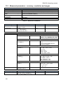
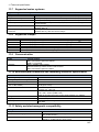
11.1 Inputs
Voltage inputs
No. of inputs
Maximum input voltage
Peak input voltage
Analog pass band (-3dB)
Transducers
Measuring inputs impedance
CMRR
Current inputs
No. of inputs
Maximum input voltage
Peak input voltage
Analog pass band (-3dB)
Input impedance
Measuring range (without
transducers)
Transducers
CMRR
5 (L1, L2, L3, N, PE - 4 measuring channels) not galvanically isolated
690VRMS
1150V
>12kHz
user defined
14MΩ (without the L1-N internal power supply in the PQM-701)
>70dB (50Hz)
4 (3 phase + neutral) not galvanically isolated
1VRMS
3.6V
>12kHz
CT clamp circuit: 100kΩ
Flexible clamp circuit: 12.4kΩ
Flexible clamps F-1/F-2/F-3: 1..3000A (10000A peak)
Clamps C-4, C-5: 1..1000A (3600A peak)
Clamps C-6: 0.01..10A (36A peak)
user defined
60dB (50Hz)
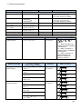
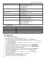
Sampling and real time clock RTC
analog-to-digital converter
16-bit
Sampling frequency
12.8kHz for 50Hz
15.36kHz for 60Hz
Simultaneous sampling in all channels
No. of samples per period
256
PLL synchronization
40..70Hz
Reference channel to PLL
L1
Real time clock
±3.5ppm max (about ±9 seconds/ month)
in the -20°C…+55°C temperature range
139