1
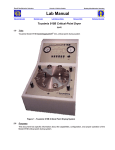
Marvell NanoLab Member login Lab Manual Contents MercuryWeb Berkeley Microlab Chapter 9.02 Karl Suss SB6 Thermocompression & Anodic Bonder (ksbonder - Microlab) 1.0 T i t le Karl Suss (Suss MicroTec) Bonder User’s Manual 2.0 Purpose This document contains information regarding to KSBonder equipment capabilities, operation instructions, processing parameters, and basic theoretical discussions of various bonding process. 3 .0 Sc ope 3.1 Overview The KSBonder is a semiautomatic, computer-controlled, stand-alone substrate bonder equipped with a vacuum/pressure chamber and a loading arm. The machine processes aligned and unaligned wafers, substrates and chips. The alignment accuracy of this tool is listed as being 3 µm (3 σ). All bonding pair alignment is done on the KSBA6 tool (Chapter 9.01), the substrate stacks are mechanically clamped using the transport fixture, and then transported and bonded in the SB6 chamber. 3.2 3.3 Equipment Capabilities ► Vacuum base pressure: 5.0E-5 Torr. ► Temperature controller limit: 500ºC ► Bonding Force up to: 60 psi (750 lbs for 4’’ wafers) Materials Allowed (It is very important to have similar thermal expansion characteristics of the bonding pair) ► VLSI materials: Silicon, PolySilicon, Silicon Nitride, Silicon Oxide ► Photo-resist (temperature no higher than 150ºC) ► Metals: Aluminum, Gold, Gold-tin alloys, Lead-tin alloys, Indium, Copper ► Glass: borofloat, Pyrex, 7740, Hoyag SD1, or any borosilicate glass with thermal characteristics matched to silicon ► Quartz ► Also, keep in mind the thickness of the wafers you wish to bond. If you plan to dice your bonded wafer stack, using standard stocked Microlab wafersaw blades, you must use wafers such that the final thickness is less than ____ microns. (Consult Matt Wasilik for this metric.) 3.4 Configurations and Components 3.4.1 Windows NT Based Control and Data Acquisition System 3.4.1.1 Each user will have his/her personal NT account and SB6 software interface account after passing the qualification exam. 3.4.1.2 Each user will have his/her personal file directory for recipe and data storage. 3.4.2 The Motorized Z drive allows different bonding sequences. ksbonder Chapter 9.2 3.4.3 4 .0 The Compressed air and N2 pressure controllers need to be turned on prior to the process. Ap p lic ab le Do cu me nts Revision History Research Report on Anodic Bonding by Ning Chen (March 2003) 5 .0 De f in it ions & Proc es s T er mino log y For anodic bonding, the working theory states that applying a large voltage potential across the glasswafer complex generates an electric field that drives Na+ ions into the glass wafer away from the interface region. Thus an Na+ depletion zone is formed leaving oxygen molecules at the interface. Oxygen molecules are then diffused into silicon to form a layer of amorphous SiO2. The setup on KSbonder is shown in Figure 1. There are two ways to orientate the bonding pairs. 5.1 With Glass – Silicon Configuration (Negative Polarity) Negative Polarity Electrodes Current direction Pyrex Silicon Chuck + Figure 1 5.2 With Silicon – Glass Configuration (Positive Polarity) Positive Polarity Electrodes + Current direction Silicon Pyrex Chuck - Figure 2 There are some differences between the two setup configurations. Negative polarity configuration with Pyrex on top, as shown in Figure 1, has a longer bonding time and better bond quality than the configuration shown in Figure 2 (Pyrex on bottom, positive polarity). For more information see Research Report by Ning Chen (March 2003). 6.0 S af et y Use common sense and general caution when approaching, and working at the machine. Watch out for potential “pinch points,” e.g. pneumatically actuated door. There is no toxic gas used at KSbonder. 7.0 S t a t i st ic a l/ P r oce ss D a t a -2- ksbonder 8.0 Chapter 9.2 A v a i lab l e P r oc ess , G ase s , P ro ce ss N o t e s 8.1 Available Tooling 8.2 8.1.1 UNI TOOL: 4’’ and 6’’ substrate capacity anodic and thermocompression bonding. The Uni-tool uses one central electrode for anodic bonding applications. This can be contrasted with the Anodic-tool, which has two concentric sets of electrodes. Because of its versatility, the Uni-tool is the default installed tooling at ksbonder. 8.1.2 TC TOOL: 4’’ substrate capactity thermal compression bonding. Note this tool rarely used since Uni-tool performs same function. 8.1.3 ANODIC TOOL: 4’’ substrate capacity anodic bonding tool. Has two concentric sets of electrodes, purportedly to enhance bonding rate and bond quality. Recommended recipe for 4’’ anodic bonding: ► Voltage: 800 V ► Polarity: Negative ► Pressure: Purge/Atmospheric ► Temperature: 450ºC These recommended parameters from results of a series of studies. For more details, please contact Matt Wasilik. 9.0 E q u ip me nt O pe rat i on 9.1 Startup Procedures 9.2 9.3 9.1.1 Enable ksbonder.. 9.1.2 Pull out and turn the compressed air and N2 gas knobs clockwise until gauge needles approximately reach the marked pressure set points. The clicking sound is normal. 9.1.3 Login to the Windows NT environment. 9.1.4 From the Window desktop, click Start Programs SB6 to start the SB6 main program. 9.1.5 Login from the navigation bar with your own user name and password. Downloading Recipe 9.2.1 Click the CONTROL CENTER icon located in the navigation bar. (Note: You will be asked if the fixture is in the chamber. Select NO if the chamber is empty.) 9.2.2 Click on Download Recipe button in the control center window. 9.2.3 Browse through the recipes in the current user directory and select the appropriate recipe for the process. (It is recommended to verify the recipe prior to load. This is described in Section IV). Loading Bonding Pairs 9.3.1 After align the bonding pair on SB6 aligner, position the fixture apparatus on the loading arm. 9.3.2 Click Load on the control center window. 9.3.3 Wait until the process chamber door opens, then push the load arm into the chamber. 9.3.4 Click Move on control center window and wait until the stage moves up and then release the fixture from loading arm. -3- ksbonder 9.4 9.5 Chapter 9.2 9.3.5 Pull out the loading arm and click Finish in control center window. 9.3.6 Click Start to run the recipe Monitoring the Process 9.4.1 Click on SB6 from the task bar. 9.4.2 In this window, many parameters are monitored and displayed: chuck temperature, chamber pressure, voltage, current, and etc. 9.4.3 Many parameters can also be monitored in continuously updated plots (located on the bottom of the screen). 9.4.4 The bonding process is completed after reaching the end point setting. This setting will be discussed in details in the recipe Section 9.7 9.4.5 A data file is automatically generated during each execution of a recipe. This file can be reviewed from Data icon on navigation bar. This data file is also stored on the hard drive under C: SB6 logfiles. The file can be also saved on to a floppy disk by click on Copy icon on the screen shown below. The data file is only available after the process is finished. Unload and Shutdown Procedure 9.5.1 Wait for the chamber to cool down to 200ºC 9.5.2 Click Unload to initiate the unloading process. 9.5.3 Once chamber door opens, push the load arm into the chamber. 9.5.4 Click Move to set the bonding pair fixture on the load arm. 9.5.5 Move load arm out of the chamber when prompt to do so. Be extra careful when sliding load arm out of chamber. The bonded wafer stack is not held in place by clamps during unloading, and can easily slide off the fixture if load arm is jerked. 9.5.6 Click Finish to close the chamber and allow machine to return to an idle state. Temperature would automatically drop down to 100ºC (?)Logout the SB6. 9.5.7 Shutdown the software. 9.5.8 Logout Windows NT environment. 9.5.9 Please, exit the SB6 software in an as delicate and orthodox fashion as possible, i.e. properly exit and end all programs before signing off. Do not Ctrl-Alt-Del or turn off computer!! 9.5.10 Turn the compressed air and N2 gas knobs counter-clockwise as far as possible. Gauge needles should read zero and machine should be silent (no clicking). This will prevent an over pressure error condition in the chamber. 9.6 Aborting a Process For whatever the reason should the user feel the need to abort a process, do not use the Abort command on the control center window. The acceptable alternative is to Pause the process and Skip through each of the subsequent steps. 9.7 Recipes The navigation bar has RECIPE option that allows user to create, edit existing recipes. All recipes for the current user are stored in C:/sb6/users/username/current/ directory (not D). If the user wishes to copy other user’s recipe, please do so in the Windows Explorer window and paste it in to the current user recipe directory. -4- ksbonder Chapter 9.2 Recipes consist of a number of sequential actions executed at specific conditions (i.e. pressure, temperature, membrane force, and voltage). Each recipe step consists of several parts. To create/load a recipe, click on RECIPE icon located on the navigation bar. To edit existing recipe, first highlight the recipe and then click Edit. This would bring out a separate recipe screen. In this screen, each of the steps can be edited. In a typical recipe, there are eight steps. 9.7.1 Bringing tool in contact with bonding pairs. 9.7.2 Removing clamps for the bonding pairs. 9.7.3 Removing spacers. 9.7.4 Bringing the inner circle electrodes in contact with bonding pair to initiate the tacking process. 9.7.5 Brief pausing. 9.7.6 Actual bonding process. 9.7.7 Cooling down to 200ºC. 9.7.8 Unloading wafers and bring machine to default state. Each of the steps can be edited by clicking on the parameter (i.e. pressure, temperature, and etc.). For example, if the user wishes to change temperature setting for a specific step, by double clicking on the temperature window, it will bring out a new temperature edit window (shown below). In this window, the use can: set the temperature; giving a tolerance; ramp up time. After changing the parameters, click OK to save. If the user wishes to apply this setting to other setups, just click on Next All. Note that tolerance settings in the recipe parameters are critical. Be sure to have the appropriate values set! Ignoring the tolerance settings can lead to unexpected process behavior. The end point setting is available in the actual bonding step. There are three different ways to define the end point: a. Percent of max current. b. dI / dt , the slop of current curve. c. Area under the curve (Q, total charge). 9.8 Changing Tooling The default tooling configuration at ksbonder is Uni-tool. That is to say, when approaching the machine in a default state, the Uni-tool will be installed. Users are allowed to change to the anodic tooling at ksbonder only when properly trained! Note that when the anodic process is finished, the Uni-tool must be reinstalled by default. Anodic tooling install directions follow: 9.8.1 Ensure that the chamber is at atmospheric pressure, and that the tooling is at room temperature. In the ksbonder software enter the CONFIG menu. Under the” Current Tool name” option, select “anodic tool”. Then select “replace tool” option. Shut the software down and turn off the computer. Press EMO button to turn off all power to the ksbonder. 9.8.2 Two persons are generally required for the following procedure. Use the lift mechanism to carefully raise the enclosure. Be careful as to not bump or scrape it on any of the components just under the enclosure. There is a delicate PCB mounted in the right hand rear corner of the chamber lid surface that can be easily damaged if care not taken. 9.8.3 Once the enclosure is lifted, use hex key to loosen and remove the bolts, one at a time, that secure the Uni-tool to the chamber. Be careful not to drop the bolts! Disconnect the -5- ksbonder Chapter 9.2 pneumatic Pa (uni tool) line, and lines 8.1 and 8.2. Disconnect the E1 and E2 electrode connections. Disconnect the JBMEM and JBC electronic connectors. Once connections are removed the Uni-tool may be gently lifted up and out of the chamber (this generally requires two persons – Uni-tool weighs roughly ~25 lbs). Be careful not to drop the tool or bump, scrape it against any other components. 9.8.4 Remove the struts that the anodic tool rests upon and re-secure to Uni-tool. Ensure oring is placed on anodic tool before insertion into chamber. Wipe all sealing surfaces clean with IPA and tech wipes. Gently place the anodic tool into the chamber. Be careful! Do not drop the tool into the chamber! Note there are alignment marks on tool and chamber to ensure correct orientation. Connect the E1 and E2 electrode connections to the anodic-tool. Install all of the bolts to the anodic tool head. They should be tightened in sequence via a “star shape”. Use hex key to tighten ¼ turn past being finger tight. Do not over tighten!!! 9.8.5 Carefully recheck all the connections and bolts. When confident everything okay, gently and slowly lower the enclosure until it is secure. Again, it is important to use caution – components can be easily broken if care is not taken. Turn equipment power back on and reboot computer. Log in to software and verify that anodic tool is seen by software in the CONFIG menu previously described. Finally, insert the red anodic tooling sign on the enclosure cover. 9.8.6 When finished processing with the anodic tool, replace with default Uni-tool. (inverse of instructions detailed above). Do not leave the anodic tool in the chamber. 10.0 Troubleshooting Guidelines Known Bugs: If the compress air and N2 gases are not turned off when machine is in idle state, it will result in over-pressure problem. Therefore, please make sure that all gasses are turned off after the process is complete. Software Problems: If the software refuses to cooperate, press CTRL+ALT+DEL to close all programs. Log out from Windows NT and log in again. Re-start the program. If the problem persists, try to do a hard reboot of the PC system. Things To Avoid: (1) Avoid using abort command while running recipes. The recipe will try to reach the specified parameters fro the step before aborting. Pausing and stepping through each step seems to be more effective. (2) Ensure that tolerances in recipe settings are correctly set. Do not ignore tolerances, as unexpected equipment behavior can result. 1 1 .0 F i gu re s & S c he mat i cs 1 2 .0 Ap pe nd ix -6-