1
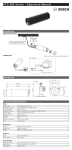
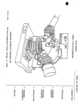
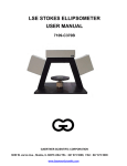
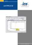
Marvell NanoLab
Member login
Lab Manual Contents
MercuryWeb
Berkeley Microlab
Chapter 8.35
Gaertner Stokes Ellipsometer
(ellips - 386)
1.0
Titl e
Gaertner Stokes Ellipsometer Operation
2.0
Pu rpo s e
The LSE Stokes Ellipsometer, made by Gaertner Scientific Corporation, uses the patented StokesMeter
technology to measure the thickness and/or the refractive index of transparent films. There is no
moving parts and no modulators in this system. It uses a 6328 Å HeNe laser at a 70° incidence angle.
The sample stage can accommodate up to 300 mm size wafers, but only the center 150 mm can be
measured at this time, as the wafer stage is stationary at this time (no X and Y stage movements
available).
GEMP Windows software can calculate the film thickness and refractive index of a layer on a substrate
or on top of a film stack that consists of three layers with known film thicknesses and refractive indices.
The measurement and calculation time of a single layer film is fast, only a fraction of a second.
3.0
S cop e
This document covers sample stage adjustment and film measurement using GEMP software.
4. 0
Appl i ca bl e Do cum ent s
Revision History
LSE Stokes Ellipsometer User Manual, 7109-C370A, Gaertner Scientific Corporation. (clean room copy
at the tool location).
5. 0
6.0
Def in it io ns & Pr oc e s s T e rm ino log y
5.1
Ellipsometry: Characterization of the optical properties of materials by examining the change in
polarization of a reflected or transmitted beam of light. By studying the complex
reflection/transmission ratio of the TM/TE electromagnetic field components, the index of
refraction and thickness in a thin-film optical system may be measured. This program calculates
two parameters, Ψ (psi) and Δ (delta) derived from the measured light wave
reflection/transmission coefficients placed in Fresnel equations, and iteratively solves for the
thicknesses and/or index of refraction.
5.2
Refractive Index (n): The real part of the optical constant of a material. It defines the phase
velocity of light in the material: υ = c / n, where υ is the speed of light in the material and c is the
speed of light in vacuum.
5.3
Extinction Coefficient (k): The imaginary part of the optical constant of a material. It is directly
related to the absorption of a material. It is related to the absorption coefficient by: α = 4 π k / λ,
where α is the absorption coefficient and λ is the wavelength of light.
S afet y
Following are the general safety guidelines in the lab as well as the specific safety rules.
6.1
Laser Safety: Observe laser caution to prevent any possible eye damage. Do not look into the
laser beam or its specular reflection.
ellips
Chapter 8.35
6.2
7. 0
Electric Shock: To prevent electric shock, do not change any switch settings and plug
connections. All the measurements are done using the GEMP software.
St at i st ic al / P roc e s s D at a
N/A
8. 0
Av ai l abl e P ro c es s es & P ro ce s s Not es
8.1
8.2
9. 0
Available Programs
8.1.1
Thin Oxide: Default program of GEMP software. It can be used to measure a single
layer oxide film about 500Å thick.
8.1.2
Thin Nitride: Default program of GEMP software. It can used to measure a single layer
nitride film about 1000Å thick.
Process Notes
8.2.1
The LSE Stokes Ellipsometer is capable of measuring the top film thickness/refractive
index of a four layer film stack. To do so, the film thicknesses and refractive indices of
the lower layers need to be measured before the top layer film is deposited.
8.2.2
The refractive index measurement is unstable in the thickness range within about 25%
of zero thickness or period value). If the oxide film to be measured is under 700 Å, the
refractive index should be entered into the computer before measurement.
8.2.3
The best film thickness for refractive index measurement is about the half the period
value, e.g. 1400 Å for Oxide and 900 Å for nitride.
Equ ip men t O p e r at io n
9.1
Equipment Description
The LSE Stokes Ellipsometer is comprised of the ellipsometer itself and table top PC running
GEMP software, running under WINDOWS OS, for film thickness and refractive index calculation.
See Figure 11.1 for the physical layout of the ellipsometer and Figure 11.2 for the display screen
of the GEMP software. There are two lasers used: One from top module for sample alignment.
The other from the left module for measurement. Both of them can be clearly seen at the center
of the sample table.
CAUTION: To prevent any possible eye damage refrain from looking into the laser beam or its
specular reflection from wafers.
9.2
Measurement Procedures
9.2.1
Enable the LSE Stokes Ellipsometer (ELLIPS).
9.2.2
Check the both lasers are ON and the center of the sample stage is illuminated.
9.2.3
Place your sample/wafer on the sample stage. You may not see the lasers light spot
because of the film on the sample. Note the measuring spot is at the center of the stage.
Sample Alignment
9.2.4
Log onto the PC. Double click the GEMP icon to start the software. Click the
ellipsometer icon on the top of the screen, or use the drop down menu under
Ellipsometer/Measurement and Calculation to open the Measurement and Calculation
Window Figure 11.2.
9.2.5
Click the Adjust Sample Table button on the left lower corner of the Measurement and
calculation screen. A new window will pop out to assist you, see Figure 11.3.
-2-
ellips
Chapter 8.35
9.2.6
Locate the X and Y plane adjustment knobs, and vertical adjustment wheel below the
sample stage, see Figure 11.4.
9.2.7
Adjust the sample tilt by turning the X and Y plane adjustment knobs until the target cross
is centered in the box shown under the TILT adjustment section of the screen.
9.2.8
Adjust the sample stage height by turning the vertical adjustment wheel until the two
horizontal cursors shown on the left side of the screen line up with each other (long bar is
even with the shorter bar).
9.2.9
Click OK button to return to the Measurement and Calculation Window.
Film Measurement
9.2.10 At the top of the Measurement and Calculation Window, enter the film stack information
for your layers or load a stack model file that has already been stored in the PC. Skip this
step if you are measuring a single layer of thin oxide or nitride.
9.2.11 For a single layer enter a rough estimate of your film thickness in the thickness1 field.
The refractive index of the film will need to also get entered or calculated by clicking on
Nf1 button, then entered in the Nf1 field.
9.2.12 Click Measure & Calculate button to perform film thickness measurement. The
measured film thickness will appear in the Measured Data windows. There are two
predefine recipes for Thin Oxide and Thin Nitride that can be used by a click of a button
at the lower left side of the screen. These can be used for single layer oxide or nitride
measurement. Please do not modify these recipe.
9.2.13 Remove your sample and logoff the WINDOWS when you are done.
9.3
Film Stack Model Set Up
9.3.1
Instrument Parameter Fields (software default, do not change)
Φ: 70° (Laser incidence angle)
Λ: 6328 Å (HeNe laser wavelength)
Ambient N: 1 (refractive index of air)
9.3.2
Film Parameter Fields (film stack information, white background)
Thickness 1: Estimated top layer film thickness to be measured.
Nf 1: Estimated top layer film refractive index to be measured.
Kf 1: Estimated top layer film extinctive coefficient to be measured. Enter 0 for
transparent film.
Thickness 2,3,4: Underlayer film thicknesses if exist. Needs to be measured before
depositing the top layer film.
Nf 2,3,4: Underlayer film refractive indices if exist. Needs to be measured before
depositing the top layer film.
Kf 2,3,4: Underlayer film extinctive coefficient if exist. Enter 0 for transparent film.
Ns, Ks: Refractive index and extinctive coefficient of the substrate
9.3.3
Calculation Modes or Combinations (selection of Thickness, Nf, and Kf buttons, do not
confused with the Film parameter Field described in the above section)
Thickness 1: Calculate top layer film thickness using the refractive index entered in Nf1
Field.
Thickness 1 & Nf 1: Calculate both the thickness and refractive index of the top layer film.
-3-
ellips
Chapter 8.35
Thickness 1, Nf1, & Autofix Nf1: Calculate both the thickness and refractive index of the
top layer film if the refractive index calculation is stable (same as Thickness 1 & Nf 1).
Otherwise, use the refractive index entered in Nf1 field (same as Thickness 1).
Thickness 1 & Thickness 2: Calculate the thickness of top two layer films using the
refractive indices entered in Nf1 and Nf2 field.
Thickness 1 & Kf 1: Calculate the thickness and the extinctive coefficient of the top layer
film. If used to measure the poly-silicon film on oxide, the thickness of the oxide film must
be precisely measured first. The thickness of the poly-silicon film should not be over
800Å.
Substrate Ns & Ks: Calculate the refractive index and extinctive coefficient of the bare
substrate. Make sure there is no native oxide film on the substrate.
9.3.4
9.4
Click Save File button to save your film stack model (all save film stack models have file
extension .tfm)
Other Operation Buttons
9.4.1
Print Measured Data Button: Print the measured data to the print area window in the
background.
9.4.2
Measure Button: Measure the sample Ψ and Δ, no calculation.
9.4.3
Calculate Button: Calculate the film properties using displayed Ψ and Δ, which can be
entered manually.
9.4.4
Enlarge Psi-Delta Map Button: Enlarge the map for what-if analysis.
9.4.5
Enable Stats Button: Calculate and display the measurement statistics.
9.4.6
Print Stats Button: Prints the displayed statistics table to the print area window.
9.4.7
Clear Stats Button: Clear and fill the statistics table with zeors.
9.4.8
Print Measured Data Button: Print Ψ and Δ and calculated solutions to the print area
window.
9.4.9
Pint Listing Button: Print the list of 10 film thickness, that correspond to the measured
Ψ and Δ, to the print area window. You can find the period value of the measured film
from the list.
9.4.10 Shortcut Buttons: These buttons can be link to film stack model files.
9.4.11 Return Button: Closes the measurement & Calculation Window and return to the print
area window.
10 . 0 Trou bl e shoot ing G u i del in e s
10.1 Problem:
Solution:
No laser light spot on the sample stage
Laser malfunction. Report problem.
10.2 Problem:
The calculated refraction index or the underlayer thickness is far from the expect
value or not repeatable.
Solution:
The film thickness is within 25% of zero thickness or period value. Change the film
thickness.
-4-
ellips
Chapter 8.35
11 . 0 Figu r es & Sc he ma t i c s
Figure 11.1 - LSE Stokes Ellipsometer Physical Layout
Figure 11.2 - GEMP Measurement & Calculation Window
-5-
ellips
Chapter 8.35
Figure 11.3 - Sample Stage Alignment Window
Figure 11.4 - Sample Stage Layout
-6-
ellips
Chapter 8.35
12.0 App end ix
Measurement Comparison of STOKE Ellipsometer, NanoDUV and Nanospec
Wafer ID
W#12
Fix RI (entered 1.456)
6859
6859
6859
Calculate RI
6818
6818
6818
1.461
1.461
1.461
RI Measured
Fix RI (computer default 1.456)
6831
6830
6830
Calculate RI
6865
6801
6861
1.449
1.463
1.450
RI Measured
Fix RI (computer default 1.456)
6886
6886
6886
Oxide
T2
#3
STOKE Ellipsometer
2928
1108
2928
1108
2928
1108
N/A
1101
1101
1101
N/A
1.461
1.461
1.461
NanoDUV
2908
1177
2909
1177
2909
1179
2916
1177
2920
1178
2977
1178
1.456
1.432
1.453
1.433
1.424
1.433
NanoSpec
2924
1112
2924
1112
2924
1113
-7-
T1
338
338
338
#4
84.7
84.7
84.6
Nitride
T9
LSN
T17
881
881
881
744
744
744
880
880
880
2.002
2.002
2.002
761
761
761
2.176
2.176
2.176
350
350
350
1.430
1.431
1.430
N/A
349
349
360
N/A
879
879
879
775
776
775
N/A
N/A
N/A
N/A
885
880
881
1.992
2.002
1.997
932
932
931
1.761
1.760
1.763
880
880
880
833
833
833
338
337
338
N/A
87.6
87.9
87.9