1
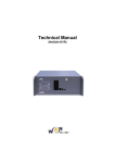
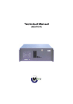
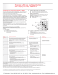
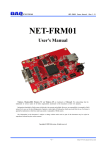
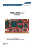
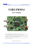
USB-FRM02 Users Manual (Rev 1.1) USB-FRM02 User’s Manual Windows, Windows2000, Windows NT and Windows XP are trademarks of Microsoft. We acknowledge that the trademarks or service names of all other organizations mentioned in this document as their own property. Information furnished by DAQ system is believed to be accurate and reliable. However, no responsibility is assumed by DAQ system for its use, nor for any infringements of patents or other rights of third parties which may result from its use. No license is granted by implication or otherwise under any patent or copyrights of DAQ system. The information in this document is subject to change without notice and no part of this document may be copied or reproduced without the prior written consent. Copyrights 2005 DAQ system, All rights reserved. -1- http://www.daqsystem.com USB-FRM02 Users Manual (Rev 1.1) -- Contents -1. Introduction 2. USB-FRM02 Functions 3. Installation 3.1 Package Contents 3.2 Installation Sequence 4. USB-FRM02 Description 4.1 USB-FRM02 Layout 4.2 Description of the functional blocks 4.3 Connector Pin-out 4.4 Sample Program 5. Test 5.1 Image Frame Test 5.2 UART Rx/Tx Test 5.3 DIO Test Appendix A.1 General Specification A.2 Physical Dimension Reference -2- http://www.daqsystem.com USB-FRM02 Users Manual (Rev 1.1) 1. Introduction The USB-FRM02 is a board to receive data from Camera-Link modulator or Image device (3.3 V CMOS Camera) and transmit the received data to the system via USB2.0 interface (High speed : 480Mbps). In addition, it has a 16 general purpose digital inputs and outputs for external controls. The operation of the board is controlled by API (Application Programming Interface) Program which can be easily installed into your PC. It has two operation modes. One is DXD810 (2048 x 1536 resolution) mode and the other is DXD1417 (3160 x 2564 resolution) mode. The difference between two modes is only the image resolution. You can select its operating mode by using the API functions. [Figure 1-1] shows connection of the PC with a USB-FRM02 board equipped into the frame grabber. [Figure 1-1. USB-FRM02 Board Usage] As shown in Figure [1-1], it receives image frame from the 3.3V CMOS interface and transmits the received data to the system via high speed USB2.0 interface. -3- http://www.daqsystem.com USB-FRM02 Users Manual (Rev 1.1) [Figure 1-2. Picture of the USB-FRM02 Board] [Figure 1-2] shows physical connection of the board USB-FRM02. At the left side, there is USB-B type connector(J1) for communication with your PC. The 24 pin connector(J4) at the upper right side is for General purpose I/O, 24 pin connector(J5) at the lower side is for UART communication and frame data channel. -4- http://www.daqsystem.com USB-FRM02 Users Manual (Rev 1.1) 2. USB-FRM02 Functions As shown in the following figure, main control of the board is performed in FPGA Core Logic. The primary functions are receiving the frame data, transmitting/receiving UART data and controlling general purpose I/O. These functions are performed by using API through USB 2.0 interface at the PC. The board has 32MByte SDRAM for buffering the frame data. USB-FRM02 USB Interface 16 Bit I/O USB High Speed Device 2.0 Specification SIE I/O Interface 4K Byte USB FIFO FPGA Core Logic UART Communication 32M Byte SDRAM FPGA Program Logic JTAG Frame Data Input 14 bit Frame Data [Figure 2-1. USB-FRM02 Functional block Diagram] Programming FPGA Core Logic is performed via the JTAG interface. The logic program of the FPGA is saved in a flash ROM, it is located on the board and loaded at the power-up time. [Features of the USB-FRM02 Board] USB 2.0 Specification, High speed(480Mbps) device 32MB SDR-SDRAM for buffering the Frame Data Single 5V operation Receiving 14-bit frame data acquisition UART communication(8 bit data, 1 start, 1 stop, No parity, 9600bps) 16 bit General Purpose I/O Windows 2000 SP4 or Windows XP SP1above Convenient Windows Application Programming Interface(DLL) -5- http://www.daqsystem.com USB-FRM02 Users Manual (Rev 1.1) 3. Installation After unpacking, inspect the board to make sure there are no damages on the package. 3.1 Package Contents [Figure 3-1. USB-FRM02 product contents] Product Contents 1. USB-FRM02 Board 2. USB(A-B) Cable 3. CD (Driver/Manual/API/Samples etc.) 3.2 Installation Sequence To install USB-FRM02 board in your environment, do the following steps. The USBFRM02 board is completely Hot-Plug and Plug & Play. Therefore, you can install it easily. The required PC operating system for the USB-FRM02 is Windows 2000 SP4 or Windows XP SP1 higher. The USB-FRM02 uses USB High Speed interface thus “USB 2.0 Root Hub” should be installed in your PC. You can check this condition by doing the following steps. [My Computer -> Properties -> Hardware -> Device Manager -> Universal Serial Bus controllers] -6- http://www.daqsystem.com USB-FRM02 Users Manual (Rev 1.1) [Figure 3-2. Select “My computer -> Properties”] [Figure 3-3. Select “Hardware -> Device Manager”] -7- http://www.daqsystem.com USB-FRM02 Users Manual (Rev 1.1) [Figure 3-4. “Device Manager” window] The item “USB 2.0 Root Hub” should be shown in the “Device Manager” window as shown in [Figure 3-4]. After checking the PC environmental conditions for USB-FRM02, do the following steps to install the board (1) Install the USB-FRM02 board into your system. (2) Power on the frame grabber. (3) Confirm the LED(D1) and LED3 on the USB-FRM02 board turns on. (4) Connect USB A-B cable between the case and your PC. The Add New Hardware Wizard will appear in order to install the driver for new hardware. (5) The Add new Hardware Wizard will install the driver in the following process. The following install process is explained based on Windows XP operating system. -8- http://www.daqsystem.com USB-FRM02 Users Manual (Rev 1.1) [Figure 3-5. “Hardware Wizard” window] If new hardware is found, Wizard will ask you to install the corresponding driver, For installation of the driver, select item “Install from a list or specific location(Advanced)” and click “Next” as in the [Figure 3-5]. [Figure 3-6. Specify the driver folder] -9- http://www.daqsystem.com USB-FRM02 Users Manual (Rev 1.1) Select “Search for the best driver in these locations”. Check “Search removable media (floppy, CD-ROM)”. Check “include this location in the search”. Click “Browse” button. Select the folder where the drivers are located. Click “OK”. Click “Next”. [Figure 3-7] will be shown. The necessary files are “usb_frm02.inf” and “usb_frm02.sys” in the driver polder. [Figure 3-7. “Device Manager” window] When you across a window’s warning message regarding to the compatibility problem as shown the [Figure 3-8] during the installation process, just click “Continue” button and go on the installation. [Figure 3-8. Warning window] -10- http://www.daqsystem.com USB-FRM02 Users Manual (Rev 1.1) If the installation is completely finished, a completion window message shall be shown as in [Figure 3-9]. Click “Finish”. [Figure 3-9. “Completion” message window] If you successfully complete the wizard, you can find the item “DRTech USB2.0 High speed frame grabber” in the “Device Manager” window as shown in [Figure 3-10]. [Figure 3-10. “Device Manager” window] -11- http://www.daqsystem.com USB-FRM02 Users Manual (Rev 1.1) 4. USB-FRM02 Description In this chapter, the primary functions of the board are described briefly. For more information, refer to the device specification. 4.1 USB-FRM02 Layout [Figure 4-1. USB-FRM02 PCB layout] The board has four LEDs to indicate the operation status. D1 : turns on when power is applied to the board. LED1 : turns on whenever the board receives the frame image data. LED2 : turns on whenever the board is transmitting the received frame image data to your PC. LED3 : turns on when power is applied and the FPGA is ready to run. -12- http://www.daqsystem.com USB-FRM02 Users Manual (Rev 1.1) 4.2 Description of the functional blocks (1) FPGA All of the functions are controlled by the logic program of the FPGA. (2) USB2.0 SIE This block supports USB2.0 High speed interface. (3) EEPROM The EEPROM contains 8051 firmware for USB2.0 SIE. (4) SDRAM The SDRAM is for saving the image frame data. The size of one frame data is 6MByte for DXD810 mode and 16MByte for DXD1417 mode. (5) Regulator The Regulator is for supplying the power (3.3V) to the board. (6) Level Shifter It is protected a circuit that the interface of high voltage higher than 3.3V CMOS Logic is exchanged to normal 3.3V Logic Level. (7) EPLD The EPLD makes a circuit for the FPGA. -13- http://www.daqsystem.com USB-FRM02 Users Manual (Rev 1.1) 4.3 Connector Pin-out The board has several connectors and jumpers to set. [J1 Connector] J1 is a USB-B type connector for high speed USB connection. [Figure 4-2] and [Table 1] shows the J1 connector and its pin description. 2 1 USB B type Connector 3 4 [그림 4-2. J1 Connector (USB-B type Front View)] [Table 1. USB-B Connector] Pin Signal Name Description 1 VCC 2 D- USB signal Minus(Negative) 3 D+ USB signal Plus(Positive) 4 GND USB power +5V Remark Not used USB power GND [J2 Jumper] J2 1 2 [그림 4-3. J2 Jumper (Top View)]] The USB-FRM02 board has powered through J5’s flat cable at normal operation. However, when the board is tested alone, a short pin can be installed on J2 pins and the power can be drawn from PC through USB connector. Important notice : Never install J2 jumper while J5 flat cable is connected. (It can be damaged PC.) -14- http://www.daqsystem.com USB-FRM02 Users Manual (Rev 1.1) [J3 Connector] J3 is used for the board self-test or the production line. Do not use at the normal operation. [Figure 4-4] shows the J3 connector. J3 1 2 3 4 5 6 [Figure 4-4. J3 Connector (Top View)] [J4 Connector] J4 is a 24 pin header for general purpose I/O. The I/O direction of each pin is determined by API. [Figure 4-5] and [Table 2] shows the J4 connector and its pin description. J4 23 24 21 22 19 20 17 18 15 16 13 14 11 12 9 10 7 8 5 6 3 4 1 2 [Figure 4-5. J4 Connector (Top View)] -15- http://www.daqsystem.com USB-FRM02 Users Manual (Rev 1.1) [Table 2. J4 PIN-OUT Description] Pin Signal Name Description 1 IO_00 General Purpose I/O 00 3.3V CMOS Logic 2 IO_01 General Purpose I/O 01 3.3V CMOS Logic 3 IO_02 General Purpose I/O 02 3.3V CMOS Logic 4 IO_03 General Purpose I/O 03 3.3V CMOS Logic 5 IO_04 General Purpose I/O 04 3.3V CMOS Logic 6 IO_05 General Purpose I/O 05 3.3V CMOS Logic 7 IO_06 General Purpose I/O 06 3.3V CMOS Logic 8 IO_07 General Purpose I/O 07 3.3V CMOS Logic 9 IO_08 General Purpose I/O 08 3.3V CMOS Logic 10 IO_09 General Purpose I/O 09 3.3V CMOS Logic 11 IO_10 General Purpose I/O 10 3.3V CMOS Logic 12 IO_11 General Purpose I/O 11 3.3V CMOS Logic 13 IO_12 General Purpose I/O 12 3.3V CMOS Logic 14 IO_13 General Purpose I/O 13 3.3V CMOS Logic 15 IO_14 General Purpose I/O 14 3.3V CMOS Logic 16 IO_15 General Purpose I/O 15 3.3V CMOS Logic 17 N.C. No Connection Never Use this pin 18 N.C. No Connection Never Use this pin 19 N.C. No Connection Never Use this pin 20 N.C. No Connection Never Use this pin 21 GND Board Ground 22 +5V Board Power(+5V) 23 GND Board Ground 24 +5V Board Power(+5V) -16- Remark http://www.daqsystem.com USB-FRM02 Users Manual (Rev 1.1) [J5 Connector] J5 is a 24 pin header connector for receiving the image frame data and supplying the power to the board. It also has the pins for UART communication. [Figure 4-6] and [Table 3] show the J5 connector and its pin-map. J5 23 24 21 22 19 20 17 18 15 16 13 14 11 12 9 10 7 8 5 6 3 4 1 2 [Figure 4-6. J5 Connector (Top View)] [Table 3. J5 Connector Pin Description] Pin Signal Name Description 1 DATA00 Frame Data 00 3.3V CMOS Logic 2 DATA01 Frame Data 01 3.3V CMOS Logic 3 DATA02 Frame Data 02 3.3V CMOS Logic 4 DATA03 Frame Data 03 3.3V CMOS Logic 5 DATA04 Frame Data 04 3.3V CMOS Logic 6 DATA05 Frame Data 05 3.3V CMOS Logic 7 DATA06 Frame Data 06 3.3V CMOS Logic 8 DATA07 Frame Data 07 3.3V CMOS Logic 9 DATA08 Frame Data 08 3.3V CMOS Logic 10 DATA09 Frame Data 09 3.3V CMOS Logic -17- Remark http://www.daqsystem.com USB-FRM02 Users Manual (Rev 1.1) 11 DATA10 Frame Data 10 3.3V CMOS Logic 12 DATA11 Frame Data 11 3.3V CMOS Logic 13 DATA12 Frame Data 12 3.3V CMOS Logic 14 DATA13 Frame Data 13 3.3V CMOS Logic 15 HSYNC Horizontal sync. 3.3V CMOS Logic 16 VSYNC Vertical sync. 3.3V CMOS Logic 17 CLOCK Frame clock 20Mhz 3.3V CMOS Logic 18 LDV Line Valid (not used) 3.3V CMOS Logic 19 RXD UART Receive 3.3V CMOS Logic 20 TXD UART Transmit 3.3V CMOS Logic 21 GND Board Ground 22 +5V Board Power(+5V) 23 GND Board Ground 24 +5V Board Power(+5V) [JP1 Connector] JP1 connector is used for the FPGA program upgrade. Never use it at the normal operation. [Figure 4-7] shows the JP1 connector. JP1 5 6 3 4 1 2 [Figure 4-7. JP1 Connector (Top View)] -18- http://www.daqsystem.com USB-FRM02 Users Manual (Rev 1.1) [JP2 Connector] JP2 connector is used for FPGA functional test. Never use it at the normal operation. [Figure 4-7] shows the JP2 connector. JP2 5 6 3 4 1 2 [Figure 4-8. JP2 Connector (Top View)] [JP3 Jumper] JP3 jumper should be shorted when upgrading FPGA program. Never use it at the normal operation. [Figure 4-9] shows the JP1 connector. JP3 1 2 [Figure 4-9. JP3 Jumper (Top View)] [JP4 Jumper] JP4 jumper determines the status of write-protection of the EEPROM. It is recommended that JP4 be open at the normal operation. [Figure 4-10] shows the JP4 jumper. JP4 1 2 [Figure 4-10. JP4 Jumper (Top View)] OPEN : Write protection. Normal status SHORT: Writing possibility. -19- http://www.daqsystem.com USB-FRM02 Users Manual (Rev 1.1) 4.4 Sample Program A sample program is provided to make the user get familiar with the board operation and to make the program development easier. You can find the sample program in the CDROM. Before using it, you have to install the board and its driver in your computer properly. Sample program is provided in source form in order to show the usage of API(Application Programming Interface) of the board and may be modified for customer’s own usage. [Figure 4-11. Main window of the sample program] To run the sample application program, you need to use API (Application Programming Interface), which is a form of client DLL (Dynamic Link Library). To compile the sample source to make its executable file, you have to use Import Library files and header files. You can find them in the CD-ROM. To run the execution file, the API DLL (USB_FRM02.DLL) must be in the same directory with the execution file or in Windows system folder. Another method is to add the directory of API DLL file to PATH environmental variable. -20- http://www.daqsystem.com USB-FRM02 Users Manual (Rev 1.1) 4.4.1 Functions related to image frame (1) DXD810/DXD1417 Combo-box Use this box to select the operation mode (DXD810 mode or DXD1417 mode). (2) ‘LVDS Init’ button When press this button, it initializes the function of receiving image frame data. It is performed only once after power is applied to the board. (3) ‘Start’ button When press this button, it start to save the image frame. (4) ‘FRAME Read’ button When press this button, it reads the image frame data saved image frame. If image data is not saved on the board, you must wait until the completion of data acquisition. (5) ‘LVDS Close’ button Press this button to finish usage of the board and terminate the program. (6) ‘Save to’ button When press this button, it saves the frame data as a file on disk. 4.4.2 Functions related to UART (1) ‘Send Serial Data’ button and editor box Press this button to send the serial data in the editor box to the frame grabber through UART interface. You can directly write the data in the editor box beside the button. (2) ‘Get Serial Data’ button Press this button to get the serial data from the frame grabber. If there is received serial data from the frame grabber, it will be displayed in the editor box below the button. (3) ‘Clear Serial Data’ button Press this button to clear the contents of the editor box. -21- http://www.daqsystem.com USB-FRM02 Users Manual (Rev 1.1) (4) ‘Start Timer’ button Press this button to start the timer. The sample program will read the UART data. The reading interval is around 100ms. (5) ‘Stop Timer’ button Press this button to stop periodical reading of UART data. (6) ‘UART Init’ button Press this button initialize UART. It must be performed only once after power is applied to the board. (7) ‘UART Close’ button Press this button to finish usage of the board and terminate the program. 4.4.3 Functions related to DIO (1) ‘DIO Read’ button Press this button to read the data on General purpose I/O ports. The I/O status is displayed on the editor box. (2) ‘DIO Write’ button Press this button to write the data in the editor box to General purpose I/O ports. (3) ‘DIO Direction’ button Press this button to determine the I/O direction of General purpose I/O ports. If you write ‘0’ to the right empty box, the port will install the input port. Otherwise, the port will install the output port. For example, if you write the value ‘0x0001’ in the editor box, port 0 shall be output port and the rest of the ports shall be input port. -22- http://www.daqsystem.com USB-FRM02 Users Manual (Rev 1.1) 5. Test 5.1 Image Frame Test In this chapter, the functional test will be explained. It is performed by the sample program “FrmTest.exe” on the PC equipped with the USB-FRM02 board. [Figure 5-1. Equipment connection for the test] [Figure 5-1] shows the connection of the equipments. The USB-FRM02 board receives power and image data from Frame Data Generator(Simulator). After completion of connecting the necessary materials, power up and execute the test program “FrmTest.exe” on your PC. Follow the steps to test the function of receiving image frame data. (1) Press the “LVDS init” button to initialize the LVDS circuit and then press the ‘Start’ button to save Image Frame data from Image Frame Simulator on the USB-FRM02 -23- http://www.daqsystem.com USB-FRM02 Users Manual (Rev 1.1) board. (2) Press the “Frame Read” button. Then data are displayed on editor box. Compare the contents of the editor box with the data of Image Frame Simulator. Comparison can be performed using the “Save to” button. It saves the contents of the editor box to a file. 5.2 UART Tx/Rx Test At the above figure [4-11], the Image Frame Simulator send to serial data to the board periodically. (1) Press the ‘UART init’ button to initialize the UART and then press the “Start Timer” button to get the UART data from the Image Frame Simulator. Then the gotten data are displayed on the editor box below button. Compare the contents of the editor box with the data of the Image Frame Simulator. (2) Write a data to the editor box beside the “Send Serial Data” and press button to send it to the Image Frame Simulator via the UART. Compare the data on the editor box with that of the Image Frame Simulator. 5.3 DIO Input/Output test At the above figure [4-11], write a “0xFFF” to the editor box of the “DIO Direction” button and press button to make all ports being output mode. (1) After to make all output port “1’’ using “DIO Write” function of the test program, check the output state using the oscilloscope or check the write data using “DIO Read” function. And then again to make all output port “0” using “DIO Write” function of the test program, check the output state using the oscilloscope or check the write data using “DIO Read” function. (2) Write a “0x0” to the editor box beside the “DIO Direction” button and press button to make all output being input mode. Each port pulls up or pulls down through 4.7K resistor and then checks all ports using “DIO Read” function. -24- http://www.daqsystem.com USB-FRM02 Users Manual (Rev 1.1) Appendix A.1 General Specification Specification General Interface Functions USB 2.0 Specification High Speed Device 480Mbps 8051 Compatible Instruction Set, 4 Clock per Cycle 32MB SDRAM +5V Single Power operation Max 300mA under 3.3V CMOS 16 bit General Purpose I/O 3.3V CMOS Camera-Link Interface. 14bit Image Frame Acquisition Transmit Image Frame Data to PC 9600bps UART Rx/Tx Software Supported OS Windows 2000 SP4 and Windows XP SP1 above API Interface with Application through client DLL Sample Software Test Sample soft ware for evaluation -25- http://www.daqsystem.com USB-FRM02 Users Manual (Rev 1.1) A.2 Physical Dimension 3.8 3.8 32 89 3.0 85 < Top View > 15.5 10.7 3.0 1.6 < Right Side View > -26- http://www.daqsystem.com USB-FRM02 Users Manual (Rev 1.1) References 1. USB 2.0 System Architecture -- Don Anderson, USB SIG(www.usb.org) 2. Universal Serial Bus Specification -- Compaq/Intel/Microsoft/NEC, MindShare Inc. (Addison Wesley) 3. AN201 How to build application using API -- DAQ system 4. AN342 USB-FRM02 API ver1.0 -- DAQ system -27- http://www.daqsystem.com