1
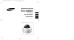
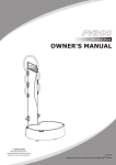
A Picture to Remember Video Screen Cinoscreen F-100 / F-AT100 Assembly Instructions Part List: Screen Fabrics Screen Fabric (F-AT models have two white woven fabrics included ) Back Fabric (F-AT models only, comes as a different package) Wooden parts Framework Bar (8 pcs) Velvet Frames (6 pcs) Corner Blocks (4 pcs) Aluminum Brackets Corner Bracket (4 pcs) Extension Bracket (2 pcs) Fabric Holder (22 pcs, 116” || 22 pcs, 136” || 26 pcs, 156”) Fabric Holder with a Plate (4 pcs) Frame Holder (18 pcs) (Do not exist if ordered with a masking system) Frame Holder Plate (6 pcs) (Do not exist if ordered with a masking system) Wall Mount (2 pcs) Wall Mount Side (4 pcs) Wall Plate (2 pcs) Wall Plate Side (4 pcs) Wall Socket, 16 mm (8 pcs) Hardware Set Screw, M4 x 30 (12 pcs) (Do not exist if ordered with a masking system) Set Screw, M6 x 30 (26 pcs, 116” || 26 pcs, 136” || 30 pcs, 156”) Set Screw, M8 x 6 (4 pcs) Washer , M10 (26 pcs, 116” || 26 pcs, 136” || 30 pcs, 156”) Hex Nut , M10 (26 pcs, 116” || 26 pcs, 136” || 30 pcs, 156”) Cap Screw, M4 x 35 (6 pcs) (Do not exist if ordered with a masking system) Cap Screw, M6 x 16 (8 pcs) Cap Screw, M6 x 25 (18 pcs) (Do not exist if ordered with a masking system) Cap Screw, M8 x 50 (4 pcs) Torx Screw, 5 x 30, black (42 pcs || 36 pcs if ordered with a masking system) INSTALLATION INSTRUCTIONS Carefully remove and unwrap all the contents of box. Referring to the parts list, make sure you have everything needed to proceed with the installation of the screen. If any parts are missing, contact Prismasonic immediately. Inspect the screen to make sure there are no shipping defects. If you notice a problem with the screen itself, or the screen’s mechanical system, contact Prismasonic immediately. Tools L-wrench, 3 mm L-wrench, 4 mm L-wrench, 6 mm Driver, Torx Spanner Wrench, adjustable Staple Gun (F-AT models only) Staples, 8 mm (F-AT models only) ------------------------------------------------------------ Video Screen Assembly Instructions Cinoscreen F-100 / F-AT100 Assembly Instructions: STEP 1 Attach the two Wall Plates and four Wall Plate sides to wall exactly as presented in Fig 1a. There are five holes in Wall Plate and three holes in Wall Plate side, which can be used for screw connections to wall. Make sure the plates are oriented correctly and the distances are as informed, depending on the screen size. After this attach the wall Sockets to the screw threads marked with x). Tighten the sockets securely and make sure the heels of sockets come in contact with the plates. (Fig 1b and Fig 1c). STEP 2 By using the L-Wrench, 3mm, screw the Set Screw m6 x 30 inside the each Fabric holder so that the bottom of the screw will be in the same level as the bottom of the holder (Fig 2a). Now prepare to attach the Wall Mounts onto the two Extension Brackets, and the Wall Mount Sides, one onto the each four Corner Brackets (Fig 2b and Fig 2c). By using L-Wrench 4 mm, tighten every Cap Screw m6 x 16 securely. Attach also the wooden Corner Block to each four Corner Bracket exactly as shown in a Fig 2d. At this point the Fabric Holder (Fig 2e) is temporarily inserted inside the Corner Block to ensure it fitting there also after tightening the Torx Screws, 5 x 30. c) NOTE: Please consult the professional installer if you do NOT know an appropriate way to attach heavy loads to your wall material. e) a) d) f) Fig 1c Fig 1b Fig 2 Fig 2 b) 116”: 1001 mm 136”: 1235 mm 156”: 1475 mm x) Fig 2 x) 116”: 1238 mm 136”: 1438 mm 156”: 1638 mm g) ... Screw also two set screws, m4 x 30 to each Corner Bracket and Extension Bracket, exactly as presented in Fig 2f and 2g, so that the screw head does not exceed the bottom surface of the bracket. x) h) As shown in Fig 2h, attach the six Frame Holders to six Frame Holder Plates with Cap Screw m4 x 35. Tighten the each screw securely by using L-Wrench, 3 mm. NOTE! Ignore the steps shown in f) , g) and h) when assemble together with the Cinomask masking system. Fig 1a Fig 2 Video Screen Assembly Instructions Cinoscreen F-100 / F-AT100 Fig 3 b) c) a) c) Fig 5 STEP 3 Starting from the upper horizontal frameworks, attach the Corner Bracket and Extension Bracket to horizontal Framework Bar with the Torx Screws, as shown in a Fig 3. Again as in case of Corner Bracket (Fig 2e), it is recommendable to insert the Fabric Holder temporarily inside the slot marked by a) to ensure it fitting there also after tightening the Torx Screws of Extension Bracket. Make also sure the Corner Bracket becomes in contact with the recess edge of Framework Bar, as marked by b). Then lift the bar hanging to the Wall Sockets of Wall Plates. wall wall b) recess c) Fig 4 STEP 4 Similarly now built the other side of upper horizontal framework bar, but now first string the Wall Mount Side to the Wall Socket in side, after which connect the other end to the Extension Bracket, exactly as presented in Step 3. Finally do the same procedure to the lower horizontal Framework Bars, which are full mirror images for the upper bars. STEP 5 Now complete the framework by adding the vertical side and center bars (Fig 5). The side bars are attached to corner brackets with Torx Screws. It is important that the side bars are oriented so that the hole on a recess of both bars are located on the side of wall (Fig 5b). Again make sure the each Corner Bracket becomes in contact with the recess edge of Framework Bar, similarly as with horizontal bars, marked by b) in Fig 3. The vertical center bars are attached to horizontal bars by two Cap Screws m8 x 50. The bars are oriented so that the recess is formed to the opposite side of wall as shown in Fig 5c. Tighten the all screws securely by using the L-wrench, 6 mm. Still screw the four Set Screws, m6 x 8 to the screw holes of both upper and lower Wall Mounts at location shown in Fig 3c to an extent that prevents the bars falling from the Wall Socket. Video Screen Assembly Instructions Cinoscreen F-100 / F-AT100 STEP 9 The fabric is now tightened first from the spots marked with arrows in Fig 8. Using the LWrench, 3mm, screw the set screws inside the Fabric Holders clock wise, each for 4-5 full turns. Before tightening make sure that in every four corner the fabric tabs bends entirely over the front edge of the fabric holder plate, exactly as shown with arrows in Fig 9 STEP 6 (F-AT models only) Connect the Black Mask Fabric onto the front side of framework by staples. Shoot one staple in about every 20 cm, after which cut the fabric to match the framework size by scissors or carpet knife. It is not important how the back fabric looks as long as it covers the area inside the outer framework bars. Neither it does not have to be 100% tensed. (It will finally be covered by the actual screen fabric and the velvet frames anyway.) Fig 7a (back view) STEP 7 Prepare to connect the Screen Fabric to Fabric Holders, which are inserted inside into the slots of framework bars, as shown in Fig 7a. Use Washer, 10 mm and Nut, 10 mm to fasten the fabric. The Fabric Holders with a Plate are placed in each four corner (Fig 7b) Fig 9 STEP 10 Now the rest of Fabric Holders are inserted to Frame work bars, and the Screen Fabric is attached to those again exactly as shown in Fig 7a. And after this those spots are also tightened according to instructions in Step 9. If there still exist some loosen areas on screen the further tightening can still be performed, until the surface is perfectly flat. Fig 11 (back view) Fig 7b a) b) a) Fig 8 STEP 8 Place the Fabric Holders first to the horizontal top frame work bars and to the top corners, after which, starting from corner, roll the fabric open and simultaneously string the tabs of fabric to every Fabric Holder on top corners and bars. After this insert the Fabric Holders also to the spots marked with the arrows in Fig 8. Now, exactly as presented in Fig 7a, lock the fabric to the holders, BUT FIRST ONLY FROM THE SPOTS MARKED WITH ARROWS IN FIG 8, even if the top bars already have the rest of holders in their place. Tighten the ten nuts securely by using the Spanner Wrench. NOTE! With F-AT model place the two white woven fabrics, one after another on top with each other, so that the one with a diagonal surface pattern stays on top. STEP 11 Velvet Frames are now attached to the framework bars. First prepare to connect the two Frame Holders to the side threads of each six velvet frame parts with Cap Screw m6 x 16 (Fig 11a). Similarly attach the frame holder assembly (Fig 2h and Fig 11b) to each center thread of velvet frame. Tighten all screws securely by using LWrench 4 mm. Finally, repeating this for all six velvet frames, string the Frame Holders in side to the set screws, assembled in Step 2 (Fig 2f and 2g), and connect the center Frame Holder with a plate onto the slot in the framework bar using the Torx Screw. Tighten the screws of each velvet frame securely using the Screw Driver, torx. Still match the joints of frames perfectly to each other and You’re done. ... Enjoy your new 2.40:1 picture! NOTE: If the motorized mask system is also installed, do not perform the step 11, but start to follow the user manual of Cinomask F-100. Care and Maintenance (CinoWhite and CinoAT Fabrics) Clean surface with a solution of mild dishwashing liquid diluted with warm water. Sponge the surface, rinse with clear water and blot dry. It is also possible to use cleaning solvents or abrasives.