1
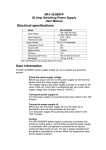
B-2530-G Instruction Manual
R. F. Amplifier
WARNING:
DO NOT PROCEED WITHOUT READING THIS PAGE.
The B-2530-G produces at least 300 watts of VHF R.F. power and is not to be taken lightly.
Severe R.W. burns can be sustained at this power level!
Power Supply: This unit was designed to operate at 13.8 volts with a power supply that provides
60 amperes continuous current. This voltage is measured under full load. The nominal current
draw of this amplifier is 46 amps, and should be considered the minimum current value. Due to
power transistors matching, some amplifiers may draw up to 50 amps and put out up to 350 watts
R.F. power. Therefore, a power supply should be selected that delivers at least 55 to 60 amps
more than the nominal current value.
Amplifier: This unit was designed to operate at I.C.S. - Intermittent Communications Service
(50% Duty Cycle, i.e., 5 minutes transmitting, 5 minutes receiving). The amplifier duty cycle
determines the dissipation rating. Ref. 1992 Radio Amateur duty Handbook page 5-9.
This unit should not be operated with the cover removed The cover confines R.F. radiation,
including harmonics, to the inside of the case. Operation of the unit without the cover could
result in direct harmonic radiation. The harmonic filters contained in the circuit will not
suppress direct radiation.
Glass mount type antennas are not suitable and may explode your window if used with this much
power.
A minimum of type RG-303 Belden Hi Temp (200c) coax must be used at the connection
between the output connector and antenna (or next stage if B-2530-G is used as a driver) or
breakdown may occur. Further, double shielded coax is recommended in mobile application as
R.F. may leak into the electrical system of the mobile application (i.e. computerized type
ignition, etc.).
The B-2530-G draws a nominal DC current of 46 amps and most alternators are rated at only
slightly above this value. Check with your owner's manual of the vehicle you plan to install the
B-2530-G in to determine if you need a larger alternator. Remember to calculate a worst case
scenario; i.e. headlights, heater (defroster or A/C), windshield wipers and radios. Remember that
alternators are rated at highway cruise speeds and not stop-and-go traffic.
MIRAGE is not responsible for dead batteries in mobile installations, or damage to anything that
was caused by poor engineering practices by the consumer of this product!
Failure to comply with these instructions may void your warranty!
1
B-2530-G Instruction Manual
R. F. Amplifier
B-2530-G
R.F. AMPLIFIER
The Mirage B-2530-G is the next generation of Power Amplifiers for 144-148 MHz.
New features make it the most useful and versatile amplifier available. Features include
automatic power shut-down circuitry for protection against high antenna VSWR, high
temperature and excessive R.F. power input. A newly designed GaAsFET receive preamp provides high gain and low noise amplification for weak signal applications. The
pre-amp includes a switchable attenuator to reduce signal output level. This is useful in
preventing Receiver Overload and subsequent Intermodulation Distortion caused by
strong signals. Provision is made for automatic or remote (external) keying, and for
remote control of all front panel functions using the Mirage RC-1 Remote Control Unit.
The Mirage B-2530-G is capable of FM, SSB, and CW operational modes.
SPECIFICATIONS:
Frequency Range ................................................................... 144 to 148 MHz
R.F. input power (Drive) ....................................................... 1 Watt to 10 Watts
R.F. output power.................................................................. 300 watts with
10 Watts drive.
Duty Cycle............................................................................. 50% "(I.C.A.S.)"
Modes .................................................................................... FM, SSB, CW
Receive Pre-amp ................................................................... Dual Gate GaSa MesFet,
Gain 22/16 dB-Nominal.
Noise figures less than 0.6
dB. 1 dB compression point
greater than -13 dBm input
(Nominal)
VSWR Power Shut-down point ............................................ 2:1 Approximately
R.F. input Power Shut-down point........................................ 30-35 +/- 5 Watts Nominal
Temperature Power Shut-down point ................................... 175 Degrees F.
Keying ................................................................................... Automatic (R.F. sensing)
or remote (external).
Input/Output Impedance........................................................ 50 ohms
R.F. connectors...................................................................... SO-239 (UHF)
Remote control connector ..................................................... RCA phono
Remote control connector ..................................................... 6 pin Molex
2
B-2530-G Instruction Manual
R. F. Amplifier
Supply voltage....................................................................... 13.8 VDC (for full R.F.
power output)
Supply current ....................................................................... 46 amps (nominal)
Circuit Breaker ...................................................................... Low voltage, fast trip.
50 amps.
Physical Dimensions ............................................................. 13 x 10 x 5 inches.
Weight ................................................................................... 13 pounds
INSTALLATION:
There must be adequate ventilation for the finned heat-sink. This generally means at least
1 inch clearance from the sink to any surrounding enclosure and an unobstructed flow
from the front to the back of the sink. CAUTION: with extended use the heat sink
becomes very hot. The D.C. power leads must use a minimum # 8 gauge wire. Use a
minimum length of good quality 50 ohm cable between the radio and the amplifier. The
antenna system should have a VSWR of 1.5:1 or better for best performance. The
receiving pre-amp gain is set to the high value at the factory. To switch to minimum gain
move the DIP switch which is located in the hole on the left side cover near the power
supply leads to the "up" position. If desired, the transmit relay hold-in (hang-time) may
be adjusted by adjusting the potentiometer located behind the slot at the rear on the left
side of the amplifier. If external amplifier keying is desired, a switched ground
connection must be provided to the center pin of the RCA jack.
FRONT PANEL SWITCHES/LED'S:
POWER ON/OFF SWITCH ..................................... Turns the D.C. power on or
(Circuit Breaker)
off.
SSB/FM SWITCH..................................................... Selects relay time delay for
the mode of operation. The
relay drop time is lengthened
for the SSB mode of
operation.
PRE-AMP ON/OFF SWITCH .................................. Turns Pre-amp power on or
off.
POWER LED (Green)............................................... Indicates that D.C. power is
applied.
PRE-AMP LED (Green) ........................................... Indicates that the pre-amp is
turned on.
TX LED (Yellow) ..................................................... Indicates that the amplifier is
keyed on.
3
B-2530-G Instruction Manual
R. F. Amplifier
FAULT (Red) ............................................................ Indicates amplifier shut-down
due to excessive VSWR,
temperature, or R.F. drive
power.
REAR PANEL CONNECTORS:
RADIO (SO-239) ...................................................... R.F. input from radio.
ANT (SO-239)........................................................... R.F. output to antenna.
RCA phono (Unmarked) ........................................... Remote keying.
Molex (Unmarked).................................................... Remote control
B+ 1/4-20 Brass Stud ................................................ + 13.8 VDC @50 amp
Connector
Ground 1/4-20 Brass Stud ......................................... Ground Connection
(WARNING the case is not
a proper DC ground.)
INTERNAL ADJUSTMENTS:
SSB DELAY ............................................................. This allows the R.F. relay
"hang-time" or delay to be
adjusted to the time desired.
PRE-AMP ATTENUATOR SWITCH ..................... Sets the pre-amp gain to full
or reduced value.
TROUBLESHOOTING:
The Mirage B-2530-G is designed for long, trouble-free performance and should not
require extensive troubleshooting in the field. Many causes of common malfunctions are
eliminated by the built-in protective circuitry. NOTE: In the event of automatic power
shut-down, the amplifier must be turned off, and the cause of shut-down determined
and removed. In case of difficulty check the following before assuming amplifier
malfunction:
a. Loose antenna or power supply connections.
b. VSWR of antenna system.
c. Coaxial cables from radio to amplifier, and amplifier to antenna.
d. Output voltage of power supply.
e. Power output of radio.
f. Improper fuse rating.
4
B-2530-G Instruction Manual
R. F. Amplifier
The WARRANTY REGISTRATION CARD must be submitted within ten days to obtain
warranty service.
MIRAGE COMMUNICATIONS assumes no responsibility for any antenna or other
accessories connected to this product.
This warranty does not apply to units that have been misused, accidentally damaged,
subjected to unusual environmental conditions, or have had unauthorized modifications
of repair.
WARNING: This unit should not be operated with the cover removed The cover
confines R.F. radiation, including harmonics, to the inside of the
case. Operation of the unit without the cover could result in direct
harmonic radiation. The harmonic filters contained in the circuit
will not suppress direct radiation.
IMPORTANT REMINDER
All MIRAGE amplifiers manufactured for amateur radio - with the exception of
repeater amplifiers - are rated as ICAS - Intermittent Commercial and Amateur
Service. This generally means 5 minute duty cycles, i.e. 5 minutes transmitting, 5
minutes receiving.
Although all of our units, except the hand helds, have thermal protection, continued
use where this cut out occurs can damage transistors.
TECHNICAL ASSISTANCE:
If you have any problem with this unit first check the appropriate section of this manual.
If the manual does not reference your problem or your problem is not solved by reading
the manual you may call MIRAGE at 601-323-8287. You will be best helped if you have
your unit, manual and all information on your station handy so you can answer any
questions the technicians may ask.
You can also send questions by mail to MIRAGE, 921 HWY 25 South, Starkville, MS
39759 or by Fax to 601-323-6551. Send a complete description of your problem, an
explanation of exactly how you are using your unit, and a complete description of your
station.
5