1
New System Manager
Installation, operation and maintenance instructions
Contents
1 - SAFETY CONSIDERATIONS................................................................................................................................................ 5
1.1 - General....................................................................................................................................................................................... 5
1.2 - Precautions against electrocution............................................................................................................................................ 5
1.3 - General installation recommendations ................................................................................................................................. 5
1.4 - Conformity................................................................................................................................................................................. 5
2 - aquasmart system DESCRIPTION............................................................................................................................ 6
2.1 - System architecture................................................................................................................................................................... 7
3 - PHYSICAL CHARACTERISTICS OF THE NEW SYSTEM MANAGER.................................................................... 9
3.1 - Dimensions (in mm)................................................................................................................................................................. 9
3.2 - Power supply.............................................................................................................................................................................. 9
3.3 - Storage........................................................................................................................................................................................ 9
3.4 - Operation................................................................................................................................................................................... 9
3.5 - LCD screen................................................................................................................................................................................ 9
3.6 - Clock........................................................................................................................................................................................... 9
3.7 - Connections............................................................................................................................................................................... 9
3.8 - Installation............................................................................................................................................................................... 10
4 - USE OF THE NSM................................................................................................................................................................... 10
4.1 - Information display................................................................................................................................................................. 10
4.2 - Use of the touch screen.......................................................................................................................................................... 10
4.3 - Use of the web interface......................................................................................................................................................... 10
5 - CONNECT THE NSM............................................................................................................................................................. 12
5.1 - Register the terminal units..................................................................................................................................................... 12
5.2 - Connect the primary and secondary buses and power supply of the NSM...................................................................... 12
6 - USE OF THE NSM................................................................................................................................................................... 12
6.1 - Screen architecture.................................................................................................................................................................. 12
6.2 - System/configuration assistant start-up................................................................................................................................ 13
6.3 - Back-up of the NSM configuration....................................................................................................................................... 19
6.4 - Loading a back-up configuration........................................................................................................................................... 19
7 - WELCOME SCREEN.............................................................................................................................................................. 19
8 - ACCESS Mode........................................................................................................................................................................ 20
8.1 - Guest mode (screen H).......................................................................................................................................................... 21
8.2 - Advanced/Service mode ........................................................................................................................................................ 21
8.3 - Reboot of the NSM application (screen H)......................................................................................................................... 21
8.4 - Display of the NSM software version (screen H)............................................................................................................... 21
9 - NSM INTERFACE CONFIGURATION (Screen A)..................................................................................................... 21
9.1 - Modify the language and the measurement system (screen A-1)..................................................................................... 22
9.2 - Find/modify information about the operating site (screen A-2)....................................................................................... 22
9.3 - Modification or adding a password or modification of the time to automatically return to the guest mode (screen A-3).. 22
9.4 - Modify date and time (screen A-4)....................................................................................................................................... 23
9.5 - Summer time control (screen A-4-1).................................................................................................................................... 23
9.6 - Configure access to the e-mail server (screen A-5)............................................................................................................. 23
9.7 - Aquasmart system management (screen A-6, Service mode only).................................................................................. 24
10 - CHILLER/HEAT PUMP MANAGEMENT (Screen F)............................................................................................. 30
10.1 - System..................................................................................................................................................................................... 30
10.2 - Find the chiller/heat pump status (screen F-2).................................................................................................................. 37
10.3 - Find the boiler status (screen F-3)....................................................................................................................................... 40
10.4 - Find the status of the air handling unit (screen F-4)......................................................................................................... 41
11 - ZONE MANAGEMENT (Screen D).............................................................................................................................. 45
11.1 - Create a zone (screen D-1).................................................................................................................................................. 46
11.2 - Delete a zone (screen D-2).................................................................................................................................................. 46
11.3 - Copy setpoint parameters from one zone to another zone (screen D-4)....................................................................... 47
11.4 - Rename a zone (screen D-3)............................................................................................................................................... 47
11.5 - Change the operating mode of a zone................................................................................................................................ 47
11.6 - Modification of a zone temperature setpoint (screen D-6).............................................................................................. 48
11.7 - Find/modify the members in a zone (screen D-7)............................................................................................................. 49
2
12 - TIME SCHEDULE MANAGEMENT (Screen E)....................................................................................................... 49
12.1 - Add a time schedule (Screen E-1)....................................................................................................................................... 50
12.2 - Delete a time schedule.......................................................................................................................................................... 51
12.3 - Copy the parameters of a time schedule to another time schedule (screen E-4).......................................................... 51
12.4 - Rename or modify a time schedule type (screen E-3)...................................................................................................... 52
12.5 - Find/modify the events of a time schedule (screen E-6).................................................................................................. 52
12.6 - Find and modify the members linked to a time schedule (screen E-7).......................................................................... 52
13 - MONITORING THE TERMINAL UNITS (Screen C)............................................................................................... 53
13.1 - Rename a unit (screen C-1)................................................................................................................................................. 53
13.2 - Copy the parameters of a unit (screen C-2)....................................................................................................................... 53
13.3 - Change the occupancy mode of a unit (C-3)...................................................................................................................... 54
13.4 - Modify a unit setpoint (screen C-4).................................................................................................................................... 54
13.5 - Find the status of a unit (screen C-5).................................................................................................................................. 55
13.6 - Find/modify the basic unit parameters............................................................................................................................... 56
13.7 - Terminal unit operating history........................................................................................................................................... 57
13.8 - Access to the advanced unit parameters (screen C-5-2-1)............................................................................................... 58
14 - EnergY MANAGEMENT (Screen G)....................................................................................................................... 62
14.1 - Configuration of the energy meter inputs of the NSM..................................................................................................... 62
14.2 - Displaying the energy meter values of the NSM............................................................................................................... 63
14.3 - Energy management............................................................................................................................................................. 64
14.4 - Total consumption for the current year.............................................................................................................................. 64
14.5 - Consumption history............................................................................................................................................................. 64
15 - ALARM DISPLAY (Screen B)........................................................................................................................................ 66
15.1 - Terminal unit alarms............................................................................................................................................................. 66
15.2 - Chiller/heat pump and CCN AHU alarms . ...................................................................................................................... 67
16 - BACnet................................................................................................................................................................................... 67
16.1 - Transform a non-BACnet NSM to a BACnet NSM.......................................................................................................... 67
16.2 - BACnet architecture............................................................................................................................................................. 67
16.3 - BACnet objects of the Aquasmart system......................................................................................................................... 68
16.4 - Note for CCN equipment types 30RB, 30RBS, 30TH, 30WG, 30XA, 30XAS, 30XW, 39SQ....................................... 71
16.5 - BACnet Protocol Implementation Conformance Statement (PICS)............................................................................. 77
17 - NSM Interface/CCN TABLES....................................................................................................................................... 79
17.1 - Table: SMSTATUS, PIC TYPE TABLE: 11H, example 1................................................................................................ 79
17.2 - Table: SMDIDO, PIC TYPE TABLE: 11H, example 2..................................................................................................... 79
17.3 - Table: NTCMAINT, PIC TYPE TABLE: 15H example 1, and Table: NTC001 to NTC128, PIC TYPE TABLE:
641H, example 1 to 128 . ...................................................................................................................................................... 79
17.4 - Table: AHUMAINT, PIC TYPE TABLE: 15H example 2, and Table: AHU024 to AHU031, PIC TYPE TABLE:
642H, example 1 to 8............................................................................................................................................................. 79
18 - COLOUR TOUCH SCREEN INTERFACE ParamETER SETTING...................................................................... 80
18.1 - Main configuration menu..................................................................................................................................................... 80
18.2 - Find and modify the NSM IP address................................................................................................................................. 80
18.3 - Configuration of the web connection.................................................................................................................................. 80
18.4 - System configuration and buzzer......................................................................................................................................... 81
18.5 - Display configuration (contrast, screensaver, calibration)............................................................................................... 82
18.6 - "Keyboard" menu................................................................................................................................................................. 82
18.7 - Password for access to the touch screen configuration..................................................................................................... 83
19 - NSM updating................................................................................................................................................................... 83
18.8 - Languages available for the touch screen configuration................................................................................................. 83
20 - TROUBLESHOOTING OF OPERATING PROBLEMS............................................................................................... 84
20.1 - Material problems................................................................................................................................................................. 84
20.2 - Problems with the use of the web interface....................................................................................................................... 84
3
LIST OF ABBREVIATIONS
AI
AHU
AO
AWG
BMS
BP
BS
C/O
CCN
CRC 2
DI
DO
EC
IEC
IR 2
LED
NC
NO
NSM
NTC
OAT
SUI
ZUI 2
Analogue input
Air handling unit
Analogue output
American Wire Gauge, American wire size standard. The equivalent cross-sections given in mm2 are approximate.
Building Management System
Primary bus
Secondary bus
Changeover (reversible)
Carrier Comfort Network (proprietary Carrier protocol)
Carrier Room Controller 2 user interface
Digital input or on/off input
Digital output or on/off output
Electronically commutated
International Electrical Commission
Infrared remote control user interface 2
Light-emitting diode
Normally closed (contact)
Normally open (contact)
New System Manager
New Terminal Controller
Outside air temperature
Simplified User Interface
Zone User Interface 2
NOTE ABOUT THIS DOCUMENT
The illustrations included in this document are for information only and not contractually binding. Carrier reserves the
right to modify the design at any time without previous notice.
The screen shots illustrate the use of the New System Manager in the English language. If there is any doubt about the
description of a control step, numbers allow the user to refer to the zone associated with the screen.
Note for BACnet:
It is strongly recommended to have BACnet training before configuring/using this function.
4
1 - SAFETY CONSIDERATIONS
1.1 - General
Installation, commissioning and servicing of the various
components of the Aquasmart system can be dangerous
unless certain aspects of the installation, such as the
presence of mains electricity and hot or chilled water in
the air conditioning equipment, are taken into account.
Only specially trained and qualified technicians and installers
who have been fully trained on the product concerned are
authorised to install, commission and service this equipment.
During servicing work, it is essential to apply all recommendations and instructions given in service leaflets, on labels
or in the instructions delivered with the equipment, and to
comply with any other relevant instructions.
•
•
•
Comply with all safety rules and regulations currently
in force.
Wear eye protectors and work gloves.
Take care when moving or positioning equipment.
1.2 - Precautions against electrocution
It is strongly recommended to disconnect the complete
power supply before any intervention. Disconnect the
main power supply with appropriate disconnect devices.
Only personnel qualified to the level recommended in
standard IEC 60364 (International Electrotechnical Commission) and trained to do this may have access to electrical
components. In particular it is obligatory to disconnect all
electrical power supplies to the unit and its accessories
before carrying out any work. Disconnect the mains power
using the disconnect device (not supplied by Carrier).
1.3 - General installation recommendations
•
To avoid interference with the connection cables:
- Keep communication wiring away from power
cables and avoid using the same cable run (300
mm maximum, common with the 230 V a.c. cable)
- Do not pass low-voltage cables through loops in
the power cables.
- Use the type of cable recommended by Carrier
(see chapter “System architecture”).
IMPORTANT: The components that make up the
Aquasmart system include electronic devices. These may
generate or be damaged by electromagnetic interference
unless they are installed and used in accordance with
these instructions. The various components conform to the
main requirements for electromagnetic compatibility in
residential and industrial areas.
1.4 - Conformity
The New System Manager has been declared to be in
conformity with the following European directives:
• Electromagnetic compatibility: 2004/108/EC
With reference to the applicable sections of the following
standards:
• IEC 61000-6-1 Immunity for residential, commercial
and light-industrial environments
• IEC 61000-6-2 Immunity for industrial environments
• IEC 61000-6-3 Emission standard for residential,
commercial and light-industrial environments
• IEC 61000-6-4 Emission standard for industrial
environments
• IEC 61131-2 Programmable controllers – Part 2:
Equipment requirements and tests
The System Manager also complies with the follwoing
European directives:
• WEEE: Waste Electrical and Electronic Equipment
20021961EC and ROHS: Restriction of Hazardous
Substances 2002195lEC.
IMPORTANT: The terminal controllers of the chiller(s)/
heat pump(s) and of the air handling unit, must have an
isolating device upstream. These safety devices shall be
sized and installed in accordance with recommendation
IEC 60364. These devices are not supplied by Carrier.
In general terms the following rules must be applied:
• The power disconnection device must be clearly labelled
to identify which items of equipment are connected to it.
• Each unit must also be clearly labelled to identify and
locate the power disconnection device to which it is
connected.
• The wiring of the components that make up the
Aquasmart system and of the communication buses
must be carried out in accordance with the latest rules
and regulations by professional installers.
• The Aquasmart system and all its components must
be installed in an environment, which conforms to the
applicable environmental characteristics.
5
2 - aquasmart system DESCRIPTION
The Aquasmart system is designed to control the comfort
in residential and light-commercial buildings as well as
office suites, hotels and hospitals. The system is characterised
by its capacity to control the operation of the various
components based on the requirements of each user on
the one hand and the building occupation time schedules
on the other hand.
It was especially developed for hydronic systems and permits
optimising the operation of each air conditioning equipment
component, while giving each user the freedom to modify
the setpoints, fan speed and operating mode, either Occupied
or unoccupied (Eco). Each system component includes all
factory-installed and tested control elements, ready to be
connected to the water and power supply of the application.
The principal system components are:
• Units for cold water production. They may be reversible
for hot water production or connected to a boiler. The
Carrier units are equipped with the communicating
electronic Pro-Dialog control.
• Terminal fan coil units, cassettes, ductable units or
wall-mounted units. These terminal units are factoryequipped with a communicating electronic control
called New Terminal Controller (NTC). A user interface
to allow adjusting the comfort parameters is also
available. For more information please refer to the
installation manuals for the terminal units.
• Air handling unit(s) for fresh air intake.
The device that controls all the equipment is the New
System Manager (NSM). The user can access it directly via
a colour touch screen interface or via a web browser.
The supported hydronic system types are:
• 2 pipes,
• 2 pipes changeover
• 2 pipes changeover + 2 wires
• 4 pipes,
• 2 pipes + 2 pipes.
Please refer to the Aquasmart Application Guide.
The New System Manager (NSM) controls the operation
of the equipment via two communication buses:
• the primary bus that links it to the chiller/heat pump/
air handling unit),
• the secondary bus that links it to each terminal unit
controller (NTC).
NOTE: Chillers/heat pumps not supplied by Carrier are
controlled by on/off outputs.
6
The NSM determines the terminal units that require cooling
and those that require heating. If the demand is above a
configurable threshold it selects the mode (this calculation
takes place every 30 seconds). It then commands the units
that can satisfy the demand. The terminal units cannot
satisfy their own demand and act to ensure that they cannot
cause any discomfort (water valve closure and fan speed
reduction).
Each piece of equipment (NTC, chiller/heat pump) continues
to ensure its own operation:
The NSM controls the changeover from occupied mode to
unoccupied mode (Eco mode) and vice-versa, based on the
individually programmable time schedule grids each zone.
A user can change the mode from his user interface from
the unoccupied mode to the occupied mode or vice versa.
The NSM is designed for easy and user-friendly operation
and:
• to configure the system,
• to set the zone parameters,
• to display equipment operation.
To track and control the energy consumption three energy
meters with pulse outputs can beconnected to the NSM.
As an option, the NSM offers a BACnet IP interface that
gives access to the predefined NTC, chiller/heat pump and
air handling unit objects.
IMPORTANT: The NSM is not compatible with the
Carrier TC (Terminal Controller) or the HDB (Hydronic
Dual Board).
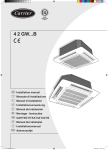
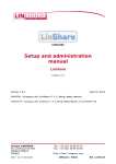
General description of the Aquasmart system
7
1
6
Legend
BPPrimary bus
BSSecondary bus
1 New System Manager (NSM)
2 Pro-Dialog+ interface
3 Boiler
4 Carrier chiller/heat pump
5 Carrier air handling unit
6 Ethernet connection
7 Web browser
2.1 - System architecture
2.1.1 - Aquasmart system structure
The system architecture includes three communication
levels:
• The so-called "primary" bus to which the NSM and
the chiller/heat pump and air handling unit are
connected. The communication protocol used is the
CCN (Carrier Comfort Network) protocol.
• The so-called "secondary bus" used by the NSM
communicates with the terminal units, and terminal
units equipped with the NTC also use this bus to
communicate with each other, if they are in a master/
slave configuration. This bus supports up to 128
terminal units. The communication protocol used is the
CCN protocol.
• The so-called "local" bus that allows the NTC to
communicate with its communicating user interface.
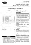
2.1.2 - Primary bus (NSM and CCN network)
The primary bus supports up to 32 CCN network elements,
including chillers/heat pumps and the Carrier air handling
unit(s) equipped with Pro-Dialog control. These units can
operate in master/slave mode.
The default CCN address (bus, element) of the NSM is
0.65. Its communication speed is 9600 baud.
Primary bus
Legend
G1Master chiller/heat pump
G2Slave chiller/heat pump
BPPrimary bus
A1 Air handling unit 1
A2 Air handling unit 2
A3 Air handling unit 3
Characteristics
• Communication support type RS485 (3 wires +
shielding).
• Recommended cable type: 3 wires or 2 twisted pairs
Belden ref. 9842. The Belden cables of series 8332,
9829, 8102, 8302 can also be used.
• Maximum length of the primary bus = 500 m, without
Carrier amplifier. These need to be installed if the
segment length is over 500 m.
• Communication protocol on the bus: Carrier Comfort
Network (CCN).
7
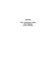
2.1.3 - Secondary bus
A secondary bus supports a maximum of 129 connection
nodes: the System Manager and up to 128 terminal units
equipped with the Terminal Controller (NTC).
The CCN address (bus, element) of the NSM on the secondary bus is 65,239 (not modifiable). Its communication
speed is 9600 baud.
Secondary bus
NTC 1
NTC 3
NTC 2
NTC 128
BS
ideal
NTC 1
NTC 2
NTC 3
NTC 128
BS
NTC 1
NTC 3
NTC 128
BS
TED
ERMIT
NOT P
Legend
NTC Terminal units with NTC (1 to 128)
BS Secondary bus
Characteristics
• Same as for the primary bus.
8
NTC 2
acceptable
2.1.4 - Connection recommendations for the primary and
secondary bus
The units are connected by a single bus cable that is
installed in cascade between the units. The number of
units connected on a bus is limited (see previous chapters).
IMPORTANT:
Instructions to follow:
• The bend radius must be higher than 20 times the
cable diameter.
• Avoid looping of the earth cable. Place the cable on
metallic structures.
• The controller connection to the bus can be made
with a cable extension, if required. All extensions
must be as short as possible, and must never exceed
1.5 m.
• Ensure that the earth potential is the same everywhere.
• Ensure that the cable shielding continuity is
guaranteed along its whole length.
• Connect one of the ends of the bus cable shielding
(only one) to the earth. The distance between the
shielding and earth must be as short as possible. If
the earth potential between the controllers is the
same everywhere, it is better to connect both ends of
the bus cable shielding.
• It is important to connect the “+” and “-” terminals
of the bus cable on the same twisted cable pair.
• To avoid any reflection in long cables, it is recommended to add an end-of-line impedance at the ends
of the bus. The NSM includes two internal end-ofline impedances (one per bus). Two accessible switches
allow adding or removing (default position) the
impedances. If the network only has a short distance,
the end-of-line impedances can be left out without
effect on data transmissions.
3 - PHYSICAL CHARACTERISTICS OF THE NEW
SYSTEM MANAGER
3.5 - LCD screen
The NSM is equipped with an LCD TFT colour screen. The
size is 5.7” and the resolution 640 points x 480 points (VGA).
3.1 - Dimensions (in mm)
Front view
This is a touch screen. It can be pressed with a finger or
with a suitable pen. Pointed or cutting tools should not be
used (e.g. screwdrivers).
NOTES: Remove the two transparent protection films.
156
Cleaning: Use only products that are suitable for LCD
screens. Do not use detergents that contain abrasives, as
they could impair the legibility of the screen texts or
damage the touch screen.
89
45,5
117
3.6 - Clock
6
202
The NSM is equipped with a real-time clock that continues
to operate for 100 hours when the NSM has no power
supply (room temperature reference is 25°C).
3.2 - Power supply
3.7 - Connections
The NSM must have a power supply of 24 V d.c. ± 20%,
max. 500 mA. The metal part of the case must be connected
to earth.
The connections are detailed on the rear face of the module.
Below the view from below and the side view of the New
System Manager.
A power supply of 230 V a.c./24 V d.c./20 VA can be
supplied as an accessory.
Reference: 33ASM-04 power supply, moulded.
Reference: 33ASM-05 power supply installed on a DIN rail.
Connections (view from below)
The ferrite supplied with the NSM must be positioned on the
24 V d.c. power supply cable, as close as possible to the NSM.
3.3 - Storage
•
•
•
Temperature: -25°C to 70°C.
Relative humidity: 10 to 98% without condensation.
Shocks (transport): complies with standard IEC
60068-2-32, mechanical shock resistance test after a
free fall from 300 mm height, repeated five times
(product weight <10 kg).
1 2 3 4 5 6
1
2
3
4
5
6
24 V d.c. GND power supply
Secondary bus (NTC) +0Primary bus (chiller/heat pump) +0Ethernet
USB
Primary bus end-of-line impedance switch closed ← → open
(default is open) (switch on the right-hand side)
Connections (side view)
3.4 - Operation
The NSM can be installed anywhere, as long as it is protected
against external elements.
Please observe the following installation precautions:
• Avoid exposing the unit to shocks or spilled liquids.
• Remove the unit from any source of electromagnetic
interference.
• Protect the unit from the sun and excessive heat sources.
• Temperature: 0°C à 50°C selon IEC 60068-2-14.
• Relative humidity: ≤ 50%, without condensation.
• Shocks: 15 G at any level for 11 ms.
• Vibration: 5 to 8.4 Hz, 3.5 mm peak movement (IEC
60068-2-6) and 8.4 to 150 Hz, 1.0 g peak acceleration
(IEC 60068-2-27).
• Protection index: IP65 (front face of the unit).
• Pollution level 2.
• Installation category II.
1 2 3
1 Connection screw to earth the NSM
2 Inputs (from left to right)
meter 3
GND
meter 2
GND
meter1
GND
digital 3 digital 2 digital 1
GND
GND
GND
3 Digital outputs (D03, D02, D01)
3 2 1
Connections (side view)
1
1 Secondary bus end-of-line impedance switch closed ← → open
(default is open) (switch on the right-hand side)
9
3.7.1 - RS485 ports
The two RS485 ports correspond to the two CCN communication buses (primary bus and secondary bus). Between
the two RS485 ports there is a switch that allows switching
off the"RS485 Primary bus" line (heat pump/chiller) to
prevent any signal reflection.
Front view:
• Switch to the left = closes the 150-ohm line (closed)
• Switch to the right = no closure (open)
3.7.2 - Ethernet RJ45 port
The Ethernet RJ45 port permits connection of the module to
the Ethernet network to access the NSM via a web browser
and/or an optional BACnet IP building control interface.
An uncrossed CAT5 cable is recommended for the connection to the building network or a point-to-point connection
to a computer.
3.7.3 - USB port
This port is only used for update and save operations of
the NSM database. Please refer to the Carrier S-Service
update tool. It is not used for other application types.
3.7.4 - Relay outputs
The relay outputs allow control of the following equipment: a
non-CCN chiller/heat pump, a boiler or an air handling unit.
They can be connected to a time schedule grid to control a
piece of equipment based on the occupancy mode. The relay
outputs are voltage-free. Relay characteristics: 24 V a.c., 1 A.
3.7.5 - Digital inputs
The digital inputs are connected to dry contacts. They allow
passing system status information to the NSM (alarms,
shut-down, loadshed, frost protection).
3.7.6 - Meter inputs
The meter inputs are connected to the pulse outputs of the
energy meters in accordance with standard IEC 62053-031.
They supply the energy consumptions to the NSM.
3.8 - Installation
3.8.1 - Flush fitting in a control box door
This installation type does not require any special kit.
• Make an opening with the following dimensions:
height = 142 mm, length = 189 mm.
• Slide the module in the opening cut out.
• Ensure that the ventilation slots (at the top and both
sides of the module) are not obstructed an allow free
air circulation.
• Install the four plastic fixing consoles (two at the top
of the module and two at the bottom).
NOTE: Use a 2.5 mm hexagonal spanner for the screws.
•
•
•
10
Tighten the screws in the consoles so that they can
always be locked to the NSM, without obstructing the
panel.
Lock them to the module, and then tighten the screws
until they touch the panel.
Tighten the screws in the normal way to a maximum
of 0.4 N·m.
3.8.2 - Flush fitted in a wall
This installation type requires a special kit, reference number
33ASM-03. The installation instructions are supplied with
the kit.
3.8.3 - Surface-mounted on a wall
This installation type requires a special kit for wall-mounting,
reference number 33ASM-02. The installation instructions
are supplied with the kit.
4 - USE OF THE NSM
Access to the data in the NSM is possible:
• via a colour touch screen interface,
• via a PC équipped with a web browser with Java
platform.
• via an iPad/iPhone, using the Carrier application
available from the Apple store
4.1 - Information display
No matter whether the colour LCD screen is used or the
web interface, the background and the format are the
same. The information and the actions are presented in
text or graphic format. Please refer to sheet 1 to find the
explanation for the icons and buttons.
4.2 - Use of the touch screen
By pressing the buttons for the zones, text zones, list
elements on the touch screen it is possible to interact with
the NSM.
4.3 - Use of the web interface
Access to the NSM is possible with a web browser and
entering the IP address of the NSM.
Minimum web browser configuration:
• Microsoft Internet Explorer version 6 or Mozilla
Firefox version 3.5.2 or higher (in the advanced
connection options add the NSM IP address to the
address list. Do not use a proxy server).
• Java platform version 6 or higher (in the control panel
untick the option that allows storing temporary
internet files and use a direct connection).
For more information on the web browser and Java
platform configuration refer to the troubleshooting section
of this document and contact your network administrator.
NOTE: It is normal to have to wait several minutes (page
loading) before the main menu is displayed.
Only one internet user is allowed at a time. When the user
disconnects, another user will be authorised to connect five
minutes later. Until the delay has expired a page indicates
to the user that too many users are connected.
SUI
24 V d.c.
power
supply
Zone 1
CRC 2
Room temperature sensor
DI unused
IR 2
Remote control via the System
Manager (public area)
Zone 2
Attention: It is imperative to connect the metal part
of the NSM box to earth.
Legend
1 Configurable digital output 1
2 Configurable digital output 2 (boiler control)
3 Configurable digital output 3 (air handling unit control)
4 Possibility to include up to 128 terminal units in the
network
5 Possibility to control all terminal units in the range,
depending on the configuration, up to seven different
channels.
6 Ensure the continuity of the shielding along the length of
the bus.
Connect one point of the shielding to the installation earth.
The total of the equipment earth must have equipotential.
DI Input via voltage-free + external alarm, shut-down of the
terminal units + demand limit, depending on the
configuration.
Slave
ZUI 2
Zone .... 32
Master
Zone
Unit
Primary bus (3 x 0.5 mm2 + shielding - max. 330 m)
Secondary bus (3 x 0.5 mm2 + shielding - max. 330
m) (128 terminal units maximum)
BL
Local bus
Note The primary and secondary buses must be
connected in series and not star-connected.
SUI
Simplified wall-mounted thermostat
ZUI 2 Wall-mounted user control box
CRC 2 Two-way control box with numerical display
IR 2
Infrared remote control 2
BP
BS
Aquasmart Evolution - typical wiring diagram (NTC)
11
5 - CONNECT THE NSM
6.1.2 - Configuration and status screens
ATTENTION: Any installation must always be carried
out with the power to the unit disconnected.
1
5.1 - Register the terminal units
Attach the self-adhesive labels, taken from the terminal
units and showing the serial number, to the site plan
(check list).
2
3
5.2 - Connect the primary and secondary buses and
power supply of the NSM
Cable material required (supplied by the installer):
• 1 small screwdriver (type AC 3.5).
• Cables type 2 x 1 mm2 (18 AWG) for 24 V d.c. power
supply
Recommended connection sequence:
• Use one of the two orange three-point connectors
supplied to connect the primary bus to the NSM.
• Use the second orange three-point connector supplied
to connect the secondary bus to the NSM.
• Use the black two-point connector supplied to connect
the power supply of the NSM.
• For the typical wiring diagram refer to the previous
page.
6 - USE OF THE NSM
6.1 - Screen architecture
6.1.1 - Configuration assistant screen
1 2 3 4
5
6
Legend
1 Screen title
2 Description
3 Editable fields
4 Message area
5 Action button area
6 Navigation button area
Use of the touch screen - editable field
To enter an alphanumeric value the user needs to press on
the editable field and a touch keyboard appears on the
screen. The new value is validated by pressing the OK key
on the keyboard.
IMPORTANT: The system uses the decimal point as the
separator.
Use of an internet browser - editable field
To enter an alphanumeric value the user needs to click on
the editable field with the computer mouse. Text modifications in the field can be made on the computer keyboard.
To validate a modification press the Enter/OK key on the
keyboard or click in an empty zone on the screen.
IMPORTANT: The system uses the decimal point as the
separator.
Action button zone
Press/click the "Edit" button to authorise the modification
of the editable fields. The "Save" and "Cancel" buttons are
now shown in place of the "Edit" button.
Legend
1 Screen title
2 Current step
3 Moving from one step to the next
For the menu architecture please refer to sheet 2.
If the "Advanced" button is shown, the user can access the
advanced functions (Advanced mode).
12
Navigation button zone
Press/click the left-hand button to show the previous unit.
Press/click the right-hand button to show the next unit.
Press/click the Up button to show the previous page of
parameters for the selected unit.
Press/click the Down button to show the next page of
parameters for the selected unit.
6.1.3 - Multiple selection screen (double list)
6.2 - System/configuration assistant start-up
Check the following points and refer to the list of check
points before continuing with the start-up:
Checks
Yes/no
The primary and secondary buses are connected to the NSM
All terminal unit labels have been attached to the installation
site plan so that they can be located easily. It is recommended
to have the plan to hand.
The metal part of the NSM casing has been connected to
earth (compulsory).
All components are energised (chiller/heat pump, NTC
controllers (terminal unit, NSM).
Check again that the physical connection of the digital inputs
and outputs is correct.
Do not connect the NSM to the local network (Ethernet)
without first configuring an IP address validated by the
network administrator.
After the first start-up the configuration assistant starts up
to guide the user through the system configuration.
1
Legend
1 Scroll-down list
The scroll-down list acts as a filter. With this list you can
display the terminal units or the zones that contain the
terminal units (left-hand list).
The selected units or zones are shown in the right-hand
column.
NOTES:
• The configuration assistant cannot be used on the
touch screen and via an internet browser at the same
time.
• If the NSM is deenergised during the configuration
assistant steps it will start-up again at the first stage.
• All configuration assistant screens will then be
accessible.
Press/click the "ALL" button to show the scroll-down list
of all units or zones in the selection list.
To select unit by unit or zone by zone
Press/click on the unit or zone name to select it. The
selected unit or zone is now highlighted.
With the arrow buttons pointing to the right the user can
move the selected units to the selection list, either one by
one or all.
With the Up and Down arrows on either side of the lists
the user can change the page. Selections made on previous
pages are kept.
With the arrow keys pointing to the left the user can move
the selected units from the selection list to the other list
(deselection), either one by one or all.
13
Configuration assistant steps
6.2.3 - Step 3 - Load or create a configuration
6.2.1 - Step 1 - Language and measurement system choice
•
•
•
•
•
Click on the flag of the required language.
Enter the currency (preferably three letters), e.g.
EUR (Euros), CHF (Swiss Francs) etc.
In the scroll-down list choose the required measurement
system.
NOTE: The selections do not need to be confirmed.
Press/click the "Next" button to move to the next step.
6.2.2 - Step 2 - Date and time adjustment
•
Loading the configuration for an existing site via the NSM
is easy with the S-Service tool of the NSM. Please refer to
the documentation for this tool.
6.2.4 - Step 4 - Information on the user site
•
•
•
•
•
14
Press/click on the field you want to change.
Enter the new value.
Press/click the "Next" button to move to the next step.
Press/click the "Back" button to move to the previous
step.
If this is the first start-up or if an old System Manager
model is replaced, the user selects "No".
If the NSM has been replaced, the user can choose
"Yes" to load a saved version of the configuration.
The configuration assistant finishes with this step.
•
•
The site information (address, telephone etc.) is
optional.
If the e-mail function has been configured, this will be
used as the message signature.
The BACnet IP interface uses the site name to name
the "Device" object of the NSM.
6.2.5 - Step 5 - Select the terminal unit search mode on the
bus
6.2.7 - Step 7 - Manual or automatic addressing of terminal
units
The use of the CCN protocol requires addressing of each
NTC controller on the secondary bus so that they can be
used. This step will allow registering the terminal units
available on the secondary bus and their CCN addressing.
(Please note that the NTC controllers are supplied
unaddressed: the default address is 0.1 for all).
The units are listed here with their serial numbers (NTC
labels attached to the plan). The list on the left shows the
unaddressed units and the list on the right shows the
addressed units.
Explanation of the three tick boxes on the screen above:
• If the first one is ticked the CCN addresses of all units
on the bus are reset to their default value (0.1).
• If the second is ticked, the system looks for unaddressed
units.
• If the third one is ticked the system looks for units
that are already addressed.
For the first start-up selection of the second tick box is
required and sufficient.
NOTE: It is possible to tick several boxes to be viewed in
the site history.
6.2.6 - Step 6 - Search for terminal units on the secondary bus
Auto addressing
If all units are in the list of unaddressed units the "Auto
Addressing" button is displayed at the bottom right of the
screen. With one press/click on the button each unit can be
automatically given a CCN address. The first unit in the list
takes adddress number 1 and so on.
Manual addressing
Press/click the serial number of the unit to be selected.
Once selected, it is highlighted. Press the right arrow button
to give the unit a CCN address. The first unit in the list
automatically receives address number 1.
Repeat this operation to address the other units. The
number displayed corresponds to the CCN address that is
given to the controller.
The text displayed on the screen corresponds to the selection(s) made in the previous step. After reading has been
completed, the "Next" button is shown.
15
To insert a unit into the list of addressed units the unit to
be addressed must be selected and then a unit in the list on
the left must be selected (see above). The insertion is always
made below the addressed unit selected.
6.2.9 - Step 9 - Selection of the hydronic system (chapter 10.1)
Press/click the button
The CCN addresses of the units following the one that was
inserted are now all moved down one unit.
If a unit address must be modified, move that unit to the
left-hand list by pressing/clicking the left arrow button and
then moving it back to the list on the right in the desired
position.
NOTE: These operations do not generate any CCN
communication and therefore no modification at the
terminal units.
This is a preparatory unit addressing step. All units
registered must be in the list on the right to be able to pass
to the nex step. Then the "Next" button is displayed.
6.2.8 - Step 8 - Writing the terminal unit addresses and
data profile of the CCN tables
The two-pipe configuration allows selection of the chiller/
heat pump unit.
The four-pipe configuration is used when the terminal unit
includes a cold water circuit and a hot water circuit.
The two-pipe + two-pipe configuration is used for installations where the terminal unit includes a single water circuit
but where control of its hot water valve allows circulation
of the water in a radiator.
For a system that includes a boiler it is always preferable to
connect this to the Carrier cold-water unit outlet provided
for this purpose in order to manage the transitions from
the cooling mode to the heating mode and vice versa in
the best way.
Possible water production configurations
Two pipes:
• Cooling only configuration with/without boiler control,
• Heat pump configuration with/without boiler control.
Four pipes and two pipes + two pipes:
• Cooling only configuration with/without boiler control.
The NSM writes the CCN addresses in all registered terminal
units and reads the CCN tables for each piece of equipment.
Once writing is completed, the "Next" button is displayed.
16
6.2.10 - Step 10 - Write the hydronic system in the terminal
units
Writing the hydronic configuration in all NTC controllers.
When writing is completed, the "Next" button is displayed.
6.2.11 - Step 11 - Selection of the chillers (chapter 9.7.3)
6.2.13 - Step 13 - Data profile of the air handling unit(s)
If no air handling unit is used, it is sufficient to specify that
the NSM does not control the AHU and go to the next step.
If this is a Carrier unit equipped with electronic Pro-Dialog+
control, the water production unit is a CCN unit. Specify
the unit CCN address on the primary bus (default is 1).
NOTE: If there is a master/slave configuration between
two Pro-Dialog units, only the master unit is controlled
by the NSM. It is therefore preferable to use address 2, for
example, for the slave unit.
If the air handling unit is not a CCN unit its control by the
NSM must be authorised and it must be indicated that it is
not CCN. Its start/stop command will be attributed to
digital output 3 by default.
If the AHU(s) is a (are) communicating Carrier units, its
(their) control by the NSM must be authorised and it must
be indicated that it is (they are) CCN.
If the chiller/heat pump is not a CCN unit, its start/stop
control will be assigned to digital output 1 by default. If
the hot water is produced by a boiler, it is automatically
given a digital output (output 2 by default).
6.2.12 - Step 12 - Data profile of the CCN chiller
This step is available if the chiller/heat pump is a CCN unit.
The NSM reads all CCN tables of the chiller/heat pump.
This step can take several minutes. The following screen is
displayed once the process has been completed.
Proceed as follows:
• If only one AHU is present, tick the box "Search for
addressed units" so that the NSM can retrieve its
identifier,
• If several AHUs are present and at the same CCN
address (24 by default), unclick this box and go to the
next step,
• If several AHUs are present and at addresses between
24 and 31, tick this box so that the NSM can retrieve
their identifiers.
NOTES:
• The NSM autorises a single non-CCN AHU or up to
eight CCN AHUs (exclusive).
• For the AHUs only the CCN addresses from 24 to 31
are autorised.
17
When reading has been completed, press the Next button.
6.2.15 - Step 15 - Writing the CCN addresses and data
profile of the CCN tables
6.2.14 - Step 14 - Manual AHU addressing
The NSM writes the CCN addresses in all registered AHUs
and reads the CCN tables of each piece of equipment.
When the step has been completed, the "Next" button is
displayed.
6.2.16 - Step 16 - Configure the digital inputs and outputs
(chapters 10.1.6 and 10.1.7)
The AHUs are identified by their MAC address (labels
supplied with the control). The list on the right contains
the addressed units, the field on the left is used to enter the
identifier of a new AHU.
NOTE: Only the last eight characters of the MAC address
are used to identify an AHU (example A8576AEF for the
MAC address DC:A8:57:6A:EF).
Addressing
• Press/click on the left-hand field of a unit to enter the
identifier of an AHU.
• Press the right arrow button to attribute it to a CCN
address. The first item in the list automatically receives
address 24.
• Repeat this operation to address the other AHUs. The
number displayed corresponds to the CCN address it
has been given.
• If a unit address must be modified, pass this unit in the
left field by pressing/clicking the left arrow button and
then place it in the right-hand list.
NOTE: These operations do not result in any CCN
communication and no modification at the AHU.
18
Possible configurations of the digital outputs
• No assignment "None": output always open.
• Controlled by a time schedule "Schedule": output
closed in occupied mode.
• Start/stop control of a non-CCN water production
unit "Chiller On/Off": output closed for the start-up.
• Heating/cooling mode control of the non-CCN water
production unit "Chiller heat/cool": output closed for
the heating mode and open for the cooling mode.
• Boiler start/stop control: output closed for the start-up.
• Air handling unit start/stop control: output closed for
the start-up. Please note that this output can also be
controlled by a time schedule.
• From the "System Alarm" information re-copy:
- system alarm present = contact closed,
- no system alarm = contact open.
•
Energy alert: this output is used together with the
energy management algorithm:
- 10-minute energy lower than the configured
threshold: contact open,
- 10-minute energy higher than the configured
threshold: contact closed.
NO means "normally open".
NC means "normally closed".
Possible configurations of the digital inputs
• No assignment "None".
• Frost protection NO/NC: allows switching all
controllers to the frost protection mode.
• Stop control NO/NC: allows switching all controllers
to the stop mode.
• Alarm, water production unit NO/NC: If a non
Carrier chiller/heat pump is in alarm status, this input
can be used to indicate that the unit is no longer
available.
• Boiler alarm NO/NC: if the boiler is in alarm status,
this input can be used to indicate that the boiler is no
longer available.
• Air handling unit alarm NO/NC: if the air handling
unit is in alarm status, this input can be used to indicate
that the air handlig unit is no longer available.
NOTE: All configurations carried out by the assistant can
be modified again later.
To completely reset the system and restart the configuration
assistant please refer to chapter 9.6.2.6.
6.3 - Back-up of the NSM configuration
It is recommended to save a back-up of the NSM database,
as this contains the complete site configuration.
This back-up can be made with the NSM service tool.
Please refer to the documentation for that tool.
6.4 - Loading a back-up configuration
Loading the database of an existing site to the NSM is easy
with the NSM service tool. Please refer to the documentation
for this tool.
7 - WELCOME SCREEN
After the configuration assistant has finished, the following
welcome screen is shown. This screen is considered as the
default screen of the NSM and will be displayed automatically after a period of user inactivity (configurable) or after
power is restored to the unit.
For these three alarms: an NO contact with open input =
no alarm, with closed input = alarm.
• Terminal unit electric heater unloading NO/NC:
together with the unloading algorithm "loadshed", this
input can be used to validate and invalidate a loadshed
period. An NO contact with open input = no loadshed.
• Energy limiting (NO): this input is used together with
the energy management algorithm:
- energy limiting activated, if the input is "closed",
- energy limiting deactivated, if the input is "open".
6.2.17 - Step 17 - End of configuration assistant
Pressing the "End" button will end the configuration
assistant and display the welcome screen (chapter 7).
Following a restart the NSM will always display this welcome
screen and no longer the one of the configuration assistant.
19
8 - ACCESS Mode
There are three access modes to the NSM functions, the guest mode (default) and the Advanced and Service modes that
require a password. The Service mode gives access to advanced CCN functions of the NSM.
Functions
System
System preferences
- Language
- Site
- Advanced/Service password
- Date and time/summer time/winter time management
- E-mail configuration
System maintenance
- See/verify/override the terminal units available on the
secondary bus
- Add/remove units
- Initialise the system
- Modify/change the chillers/heat pumps
- BACnet (network number, NSM instance)
Alarms
Display unit/CCN chiller/heat pump
Terminal units
- Name/occupancy mode/operating mode/setpoint temperature
- Renaming
- Configuration copy
- Setpoint
- Room temperature/fan speed/water temperature/water valve
control status/electric heater control status/digital NTC input
status
- Occupancy period control
- NTC CCN tables
- Master/slave configuration
- Zoning configuration
- Trend tracking
- BACnet configuration (COV, alarm, notification)
Zones
- Creation
- Renaming
- Copying
- Deletion
- Setpoint
- Members
- Occupancy period control
Time schedules
- Creation
- Renaming
- Copying
- Deletion
- Time schedule events
- Members
Production
System
- System Manager
- Algorithm (on/off)
- Advanced algorithm configuration
- Hydronic system configuration
- Summer winter setpoint
- Digital input/output configuration
- BACnet configuration (COV, alarm, notification)
- Water production unit
- Status
- Trend tracking
- BACnet configuration (COV, alarm, notification)
- Air handling unit
- Status
- Air handling unit algorithm
- Trend tracking
- BACnet configuration (COV, alarm, notification)
- Energy
- Metering input configuration
- Consumption
- Consumption history
Guest
Accessible
Configurable
X
X
X
X
X
X
X
X
X
X
X
X
X
X
Advanced
Accessible
Configurable
Service
Accessible
Configurable
X
X
X
X
X
X
X
X
X
X
X
X
X
X
X
X
X
X
X
X
X
X
X
X
X
X
X
X
X
X
X
X
X
X
X
X
X
X
X
X
X
X
X
X
X
X
X
X
X
X
X
X
X
X
X
X
X
X
X
X
X
X
X
X
X
X
X
X
X
X
X
X
X
X
X
X
X
X
X
X
X
X
X
X
X
X
X
X
X
X
X
X
X
X
X
X
X
X
X
X
X
X
X
X
X
X
X
X
X
X
X
X
X
X
X
X
X
X
X
X
X
X
X
X
X
X
X
X
X
X
X
X
X
X
X
X
X
X
X
X
X
X
X
X
X
X
X
X
X
X
X
X
X
X
X
X
X
X
X
X
X
X
X
X
X
X
X
X
X
X
X
X
X
X
X
X
X
X
X
X
X
X
X
X
X
X
X
X
X
X
X
X
X
X
X
X
X
X
X
X
X
X
X
X
X
X
X
X
X
X
X
X
X
X
X
X
X
X
X
X
X
X
X
X
X
X
X
X
X
X
X
X
X
X
X
X
X
X
X
X
X
NOTE: Certain configuration modifications also require system shut-down (see chapter 10.1.1).
20
X
X
X
X
X
8.1 - Guest mode (screen H)
8.3 - Reboot of the NSM application (screen H)
To access screen H press/click the button
The reboot function of the NSM application is available
with the "Reboot" button.
The guest mode allows the user to control all daily system
operations.
By default access to this mode is possible without password,
but access with a password can be configured (see chapter
9.3).
This function is useful to reorganise and display the unit,
zone and time schedule names in alphabetical order.
8.4 - Display of the NSM software version (screen H)
The NSM software application version is displayed here,
for example ECG-ST-20KE6030.
9 - NSM INTERFACE CONFIGURATION (Screen A)
Access to the NSM configuration parameters is from the
welcome screen, pressing the button"System Settings"
(screen A).
8.2 - Advanced/Service mode
Access to this mode is password protected.
To connect in the Advanced or Service mode and to access
screen H press/click the following button on the welcome
screen:
Press/click in the editable field and enter the password for
the Advanced or Service mode.
NOTE: As the default there is no password. To connect
simply validate an empty field.
If the password is correct, the OK button is shown.
The "Logout" button allows return to the guest access
mode.
This screen allows access to:
• the language and unit of measurement selection
(chapter 9.1),
• the site information (chapter 9.2),
• the Advanced and/or Service password modification
and inactivity periods that allow return to the welcome
screen and to the guest access mode (Advanced and
Service modes only),
• the date and time adjustment (chapter 9.4) and the
modification and activation of the summer to winter
time changeover and vice versa,
• the configuration of the e-mail server properties,
• The "System Management" menu is only accessible in
the Service mode. It allows access to advanced system
and maintenance functions.
21
9.1 - Modify the language and the measurement
system (screen A-1)
In screen A (System Settings), press/click the "Language"
button (screen A-1). See section 6.2.1.
Procedure for selecting a language and/or adding a language
• Use the NSM service tool (refer to the documentation
for this tool) to recover the language files.
• The language file is a text file. It is editable with the
Windows noteblock. A semicolon separates the text in
the English language from the translated text. Only
the translated text that is after the semicolon must be
modified. Carry out the required modifications.
• Use the NSM service tool to download the file of the
modified language.
The language file, that is accessible when pressing/clicking
the flag for Esperanto "Other" has the name "lngOther.csv".
It can be used to translate the NSM into a language that is
not in the list. To translate the NSM into that language,
use the same operating mode as before.
9.2 - Find/modify information about the operating site
(screen A-2)
In screen A (System Settings) press/click the "Location"
button (screen A-2). See section 6.2.4.
22
9.3 - Modification or adding a password or modification
of the time to automatically return to the guest mode
(screen A-3)
Connect in the Advanced mode. In screen A (System
Settings) press/click the "Security" button (screen A-3).
The "Service" access level allows display and configuration
of all NSM parameters, but also read/write access to the
CCN tables of the terminal units. Only a user with "Service"
access can modify the "Service" password.
The "Advanced" password allows access to the advanced
NSM parameters.
The "Guest access" password allows any user secure access
from a web browser and/or the touch screen interface.
If the "Ask Password" parameter has been configured to
"Network" or "local", the "Guest user"password will be
requested before the welcome screen is displayed for
access via a web browser or via a touch screen interface.
If the "Ask Password" parameter has been configured for
"any user", a password will be requested before the welcome
screen is displayed for access via a web browser or via a
touch screen interface
If the "Ask Password" parameter has been configured to
"Never", no "Guest access" password will be requested.
Password modification
• Press/click the "Edit" button.
• Press/click the field to be modified and enter the new
password. Confirm this.
NOTE: It is not possible to enter a blank field as password.
Modification of the inactivity time that allows automatic
return to the guest mode and to the welcome screen
• Enter the number of minutes (from 5 to 120 minutes)
at the end of which the system returns to the guest
mode and to the welcome screen.
• Press/click the "Save" button.
• Press the "Logout" button to reactivate the security
settings.
To change them:
• Enter the new value.
• Press/click the "Save" button.
9.6 - Configure access to the e-mail server (screen A-5)
In screen A (System Settings), press/click the "E-mail
Server" button.
9.4 - Modify date and time (screen A-4)
In screen A (System Settings), press/click the "Date &
Time" button (screen A-4). See section 6.2.2.
•
•
•
NOTE: The information about summer time control is
given for information only and cannot be changed. It is
activated when the changeover to summer time takes place.
9.5 - Summer time control (screen A-4-1)
In screen A-4 (Date & Time) press/click the "More" button
(screen A-4-1).
"Sender: indicates the NSM address. This can be
chosen, as preferred by the user, but certain servers
may require authentication.
"Recipient": e-mail address of the recipient (maximum
two recipients).
"Send e-mail":
- Tick the box "when an alarm occurs" to receive
an e-mail when an alarm appears on one of the
terminal units or chillers/heat pumps or air CCN
handling units. A text file containing the description
of all detected alarms will be attached to the
e-mail.
- Tick the box "with energy consumption every
month" to receive an e-mail containing the daily
energy consumption since the beginning of the
calendar year each month. An e-mail per meter
will be sent together with an attached file showing
the consumption in .csv format.
Press/click the "Next" button to display the e-mail server
properties.
The default values have been defined for European countries.
23
•
"Outgoing mail server SMTP": "Port Number" and
server ask for the network administrator e-mail server
IP address, the port number used (default is 25) and
the maximum server response time.
If the server requires authentication, tick the box and fill in
the fields "Account Name" and "Password".
Verify that the "Network" configuration of the NSM is
valid (see chapter 16).
The "Test" button allows sending an e-mail to validate the
configuration.
9.7 - Aquasmart system management (screen A-6,
Service mode only)
Reserved for the Service mode.
Access to the NSM system management is from the welcome
screen by pressing the "System Settings" button (screen A)
and then the "System Management" button (screen A-6).
9.7.1 - Force/release the terminal unit controller outputs
(screen A-6-1)
Access to this NSM system management screen is from the
welcome screen by pressing the "System Settings" button
(screen A), then the "System Management" button (screen
A-6) and then the "Force" button (screen A-6-1).
To select the units or zones to force/release please refer to
section 6.1.3.
Once the selection has been made, press/click on the "Next"
button.
Select the outputs to be forced or released, or enter the
override value.
To force a setting, select the override value and transmit
the override parameter by clicking the "Force" button.
Once the system management operation has been completed,
the selected outputs must be released by pressing the "Auto"
button or switching off the power supply to the relevant
NSM and then switching it back on.
The following screen will then be displayed, indicating the
writing progress for the terminal units. If this is not the
case, an error message will be displayed (communication
problem, insufficient priority).
The NSM forces the CCN variables to a "Supervisor" level.
24
9.7.2 - Terminal unit database management
9.7.2.1 -Database management in a list of the terminal
units (screen A-6-2)
Access to this NSM system management screen is from the
welcome screen by pressing the "System Settings" button
(screen A), then the "System Management" button (screen
A-6) and then the "Unit Database" button (screen A-6-2).
The up/down arrows on the right-hand side of the list
display the next or previous page.
9.7.2.3 -Verification of the availability and integrity of
units on the bus with the units in the database (A-6-2-2)
The Service mode is required.
Press/click the"Verify/Update" button (screen A-6-2). To
carry out this operation it is necessary to first deactivate
the system control by the NSM. Go to screen F-3-3 and
deactivate the NSM control.
This operation is in two steps:
• The first step scans the secondary bus. The NSM
searches for addressed and unaddressed units.
This screen gives access to:
• the registration of the terminal units controlled by the
NSM,
• the verification of the database integrity compared to
the units actually connected to the bus,
and permits:
• adding/removing one or several terminal units,
• removing the NSM database and resetting the CCN
addresses of the terminal units to their default value
(0,1). This action allows a return to the configuration
assistant (see section 6.1.1).
•
During the second step, the NSM compares the units
found with the units shown in the database and indicates
any differences in a list.
9.7.2.2 -Access to the units registered in the database (A6-2-1)
The Service mode is required.
Press/click the "View" button (screen A-6-2).
This screen lists all units included in the database. CCN
and serial number columns indicate the equipment CCN
address on the secondary bus and its serial number.
25
See section 6.2.5.
Press the "Next" to go to the next step and carry out the
search.
Step 2
The possible differences are:
• "Not found": The unit is included in the database, but
cannot be found on the bus. Verify that the unit is
energised, that the CCN connector is correctly fitted.
If the unit no longer exists, it must be removed from
the database (see screen A-6-2-4).
• "Unknown": A unit present on the bus is not shown in
the database. If this is replacement unit, select the unit
and press the "Replace" button. Then select the unit
to be replaced in the list.
• "Mismatch": The CCN address and the serial number
do not correspond to those registered in the database.
Select the unit and use the correction button "Match"
to update the database.
See section 6.2.6.
Once the search has been completed, the "Next" is shown.
Press/click the button to display the units found.
Step 3
Once a difference has been corrected, the unit(s) concerned
are automatically removed from the list.
9.7.2.4 - Add units to the database (A-6-2-3)
The Service mode is required.
Press/click the "Add"button (screen A-6-2).
To carry out this operation, it is necessary to first deactivate
the system control by the NSM. Go to screen F-3-3 and
deactivate the NSM control.
This operation includes four steps.
Step 1
Go to menu A-6-2-3 and select unaddressed units and/or
units addressed with the CCN search function.
See section 6.2.7.
After all units have been addressed, press/click the"Next"
button to go to the next step.
26
Step 4
The NSM writes the CCN addresses in all terminal units.
9.7.2.6 -Re-initialize the database (A-6-2-5)
The Service mode is required.
Press/click the "Initialize All" button (screen A-6-2)
ATTENTION: This operation erases the database, and
initializes the CCN addresses of the controllers. The NSM
will then restart as in the first start-up with the configuration
assistant screen.
The confirmation screen is then displayed:
See section 6.2.8.
9.7.2.5 -Removal of units from the database (A-6-2-4)
The Service mode is required.
Press/click the "Remove" button (screen A-6-2).
To carry out this operation, it is necessary to first deactivate
the system control by the NSM. Go to screen F-3-3 and
deactivate the NSM control. Then go to menu A-6-2-4 and
confirm the progress of the operation.
Press/click "Yes"to confirm the complete system initialisation. The following screen will display the continuation of
the first screen of the configuration assistant (see 6.1.1).
The list of units present in the database is displayed. Press/
click on the name of a unit to select it. Once selected, it is
highlighted.
Press/click the "Remove" button to remove the units from
the database.
NOTE: During this operation, everything is deleted
including the Advanced password which is returned to its
default value.
27
9.7.3 - Modify/update the CCN and non-CCN chiller/heat
pump
The Service mode is required.
This function is necessary to update the CCN parameters
of the chiller/heat pump if its software is upgraded.
In screen A6 press/click the "Chiller/HeatPump changes"
button to move to screen A-6-3 and choose the chiller/heat
pump control mode. See section 6.2.11.
If the chiller/heat pump is a non-Carrier unit it is a nonCCN chiller/heat pump and the digital NSM output to be
used for the control must be indicated.
A back-up of the parameters above results in a new CCN
data profile of the unit.
For reversible non-CCN units, the heating/cooling control
will be assigned as a default at the second digital output.
See section 6.2.12.
Once the data profile has been completed, the following
screen is displayed:
28
9.7.4 - Modifying/updating CCN and non-CCN air handling
units
The Service mode is required.
This function is required to update the CCN parameters of
the air handling unit(s) and to add or remove one or several
air handling units.
In screen A6 press/click on the button "AHU changes" to
display screen A-6-4 and authorise the NSM command to
the air handling units.
See section 6.2.11.
A back-up of the parameters above results in a new CCN
data profile of the air handling unit(s).
If the air handling unit is not a Carrier unit, it is not CCN
and the digital output of the NSM to be used for the
control must be indicated.
In this screen it is possible to add new air handling units
(see section 6.2.13).
9.7.5 - Starting/stopping BACnet
Reserved to the Service mode.
If the BACnet option is supported by the NSM, access to
the BACnet configuration parameters of the NSM is from
the welcome screen by pressing the "System Settings" button
(screen A), then the "System Management" button (screen
A-6), and finally the "BACnet" button (screen A-6-1).
29
To access this screen, system control by the NSM must be
deactivated (see screen F-1-3).
By default the BACnet option is not allowed to start. Once
the system operates correctly, BACnet can be authorised to
start (enable) and if required later to stop (disable).
It is recommended to refer to chapter 16 for more information about the BACnet IP interface supported by the
Aquasmart system.
10 - CHILLER/HEAT PUMP MANAGEMENT (Screen F)
Access to the chiller/heat pump NSM parameters is from
the welcome screen by pressing the "Production" button
(screen A).
Depending on chillers/heat pumps listed in the NSM, the
buttons and information relating to the "Boiler" and the
"Air Handling Unit" can be masked.
IMPORTANT: The NSM must be re-started in order to
take the modifications made into consideration.
9.7.6 - Deleting all BACnet configurations made
In this screen tick the "Clear BACnet configuration" box and
save to delete all BACnet configurations made (COV, alarm,
notification). When the NSM restarts a new BACnet database with the default parameters will be created automatically.
IMPORTANT: The NSM must be re-started in order to
take the modifications made into consideration.
This screen gives access to:
• the system start-up and configuration,
• the chiller/heat pump status and configuration,
• the boiler status (if used),
• the air handling unit status and configuration (if used).
10.1 - System
Access to this NSM maintenance screen is from the welcome
screen by pressing the "Production" button (screen A) and
then the "System" button (screen F - screen F-1).
9.7.7 - Modifying the BACnet network numbers and the
NSM instance number
Reserved to the Service mode.
The virtual BACnet numbers and the NSM identifier must
be modified if several Aquasmart systems are located on the
same BACnet IP network so that each device has its own
unique identifier.
This screen gives access to:
• the system start-up and configuration,
• the algorithm start-up,
• the hydronic system configuration,
• the summer and the winter setpoint configuration,
• the digital output configuration,
• the digital input configuration.
• the configuration of the BACnet options (COV,
alarms) and the alarm notification
30
10.1.1 - Authorisation/deactivation of the system control
via the NSM (Screen F-1-3)
In screen F-1 press/click the "System" button to move to
screen F-1-3.
Authorisation of system control via the NSM
This point allows the Aquasmart system to enter the
operating phase. To authorise, select "Yes". After the point
status goes to "Yes", the NSM carries out the calculations,
activates the time schedules, carries out a periodical check
of the terminal units, determines a system operating mode
and acts on the chillers/heat pumps.
To save energy it is possible to tick the box "Disable
cooling in unoccupied mode" to stop the cooling mode
when all units are in an unoccupied period.
If the status is "No", the installer can carry out a maintenance operation without interference or disturbance with
the operation of the NSM algorithms.
10.1.2 - Modify the water circuit type and the water
production source (screen F-1-1)
Advanced mode required for this modification.
NOTE: It is recommended to validate the NSM control
once the system is fully operational.
In screen F-1 press/click the "Hydronic System" button to
enter screen F-1-1. See section 6.2.9.
Demand mode override
The mode can be forced by pressing the "Edit" button for
a given time to the following values:
• cooling,
• heating,
• neither cooling nor heating,
• no override (default).
Demand override duration
• limit values: 1 hour to 12 hours,
• default value: 1 hour.
If the hydronic system configuration is modified, the NSM
writes the configuration to the controllers: see section
6.2.10.
31
10.1.3 - Configure the broadcast of the unit leaving water
temperature from the CCN chiller/heat pump to the terminal
units (Screen F-1-1)
Advanced mode required for a modification.
10.1.4.1 - Activate/deactivate and find "Smart Start" status
"Smart Start" allows the NSM to determine the time
needed to reach the setpoint temperature configured for each
unit at the programmed start time of the occupied period.
Ticking the box allows the leaving water temperature of the
Carrier chiller/heat pump to be broadcast to the terminal
units every three minutes. The broadcast is effective if the
NSM is authorised to control the complete equipment.
If it is activated, the algorithm operates if the first occupied
period of the time schedule is after 1.00 a.m.
To activate/deactivate "Smart Start", click on the edit
button (at the bottom left) of screen F-1-2 and select "On".
Display of the detailed information requires the Advanced
mode. To find the detailed "Smart Start" status, press the
information button for "Smart Start".
NOTE: The unit hot water leaving temperature does not
consider the temperature increase due to the additonal
electric heater stages.
10.1.4 - Configuration of the NSM algorithms (screen F-1-2)
This screen indicates the current algorithm status.
• The "Smart Start" algorithm allows daily change of
the unit start-up and of the terminal units to occupied
mode at seasonal conditions.
• The "Loadshed" algorithm allows electric heater
unloading for the terminal units selected after reading
a digital input.
• The "System Mode Threshold"algorithm can determine
the units to be taken into consideration when calculating
the cooling and heating demand.
The Advanced mode is required if detailed information on
the operation of these algorithms is required.
In screen F-1 press/click the "Algorithm" button to enter
screen F-1-2.
Four-pipe configuration has two additional status fields.
"Smart start" authorisation
Ths status indicates if "Smart Start" is active or not.
Demand mode
This is the result of the calculation carried out by the NSM,
and acts on an operating mode in order to satisfy the first
setpoint of the first occupied period.
It can have the following values:
• No mode: the NSM cannot determine a smart start
mode for the system. Normally the NSM is not active
or the smart start algorithm is not.
• Cooling: the NSM has determined that there is a cooling
demand for the water circuit in order to satisfy the
first controllers for the first occupied period of the day.
• Heating: the NSM has determined that there is a heating
demand for the water circuit in order to satisfy the
first controllers for the first occupied period of the day.
• Cooling/heating: in 4-pipe applications only this mode
indicates that the heating and cooling demands of the
units installed must be satisfied.
• None: the system has not found sufficient reason to
anticipate switching on any operating mode.
32
Anticipated heating and cooling demands
These are the ratios between the controllers that will have
a cooling or heating demand to reach their occupied
setpoint value for the first time schedule period and the
total number of controllers. The value is expressed in %.
These values in minutes show the time required for the
hydronic system to reach the conditions required to trigger
the reverse mode, i.e. for the water circuit to change from a
cooling temperature (< 15°C) to a heating temperature (>
35°C) or vice versa (heating to cooling).
Cooling/heating algorithm status
This information allows the operator to know where the
calculation determination is relative to this algorithm.
These values are only used when "Smart Start" is active.
It can have the following values:
• Blocked: The NSM has not been activated, the
Optimised Start has not been activated or the system
mode is No Mode.
• Inactive: The NSM has already determined a reset
time for the day, the System Mode is None.
• Search Mode: The NSM is busy calculating a mode,
but for the moment there is no dominant demand.
• Maintain Mode: The Smart Start mode is other than
None and stays at that value, as the time counters have
not completed their count.
Cooling/heating mode delay
Following the selection of the Smart Start mode a time
counter or delay is initialised by the corresponding value.
• A - If the Smart Start mode changes to cooling, the
counter value will be the same as the delay chosen for
the "cooling delay" parameter for the water circuit (5
minutes minimum). During the count of this delay, the
Smart Start mode remains in cooling mode and at the
end of the count demand selection for each controller
is stopped. This only applies from 1.00 a.m. until the
beginning of the first occupied period.
• B - If the Smart Start mode changes to heating, the
counter value will be the same as the delay chosen for
the "heating delay" parameter for the water circuit (5
minutes minimum). During the count of this delay, the
Smart Start mode remains in heating mode and at the
end of the count demand selection for each controller
is stopped. This only applies from midnight until the
beginning of the first occupied period.
These values depend on the correct factors for the system,
but they should be estimated at the beginning based on the
piping length, the number of terminal units and the capacity
at a sudden change from heating to cooling mode by the
chiller/heat pump controller.
Example: For a medium-sized system (around 30 terminal
units) an reset time of 5-15 minutes is reasonable. The
longer the time, the earlier the unit will start up to ensure
that the setpoint is reached in the zones at the time when
the occupied mode begins.
10.1.4.3 - Parameter setting for the terminal unit electric
heater unloading
Advanced mode required.
To activate electric heater:
• Go to screen F-1-2.
• Press/click the configuration button for "Loadshed".
10.1.4.2 - "Smart Start" parameter setting
To set the "Smart Start" temperature parameters for the
water circuit, press/click on the edit button for "Smart Start"
in screen F-1-2.
Select the zones and/or units concerned.
Press/click the "Save" button. The NSM writes the loadshed
authorisation to the selected terminal units.
33
To find out the threshold at which the system demand
changes to heating mode or to cooling mode press/click
the "Edit" button.
The loadshed algorithm is activated. To deactivate electric
heater unloading:
• Go to screen F-1-2.
• Press/click the configuration button for "Loadshed".
• Do not select any units/zones to unload and save. The
NSM writes and prohibits unloading to the terminal
units selected.
• The loadshed algorithm is deactivated.
NOTE: A digital input on the NSM must be configured.
Depending on the status of this input, the electric heaters of
the selected terminal units will be authorised or unloaded.
See section 10.1.7.
10.1.4.4 - Modification of the heating/cooling thresholds to
calculate the system demand
Advanced mode required. The NSM determines the heating
and/or air conditioning requirements taking into account
the demand of each terminal unit and the configured heating
and cooling mode.
To find out the current cooling and heating demand, go to
screen F-1-2 and then press/click the information button
for "System Mode Threshold".
These demands in percent correspond to the ratio of
terminal units in cooling/heating demand compared to the
number of terminal units taken into consideration for the
calculation (default is all).
If the demand is higher than one of the thresholds, the
NSM can control the hot and/or cold water production.
• Limit values:
0 - 100%
• Default value:
50%
Example: If the system includes 26 terminal units and if
the cooling mode threshold is fixed at 50%, there must be
at least 26 x 0.5 = 13 units in cooling demand before the
NSM changes to cooling mode.
The first parameter "Use Cooling Capacity" relates to the
terminal units. It allows taking the cooling capacity of each
unit into account in order to weight its demand in cooling
mode only.
ATTENTION: By default the terminal units are configured
with cooling capacities of zero. To use the weighting, this
parameter must be re-assigned in each NTC controller.
10.1.4.5 - Taking only certain units into account for the
heating and cooling demand
To select the units to be taken into account for heating and
cooling demand, click on the edit button (at the bottom left)
of screen F-1-2.
Two modes are authorised:
• The default mode to carry out the system demand
calculation with all terminal units.
• The custom mode to carry out the system demand
calculation with selected terminal units.
Save the selection.
In the "Custom" mode and in the Advanced mode a
configu-ration button appears for the "System Mode
Threshold" next to the information button:
34
To select the units to be taken into account for the system
demand calculation press/click this button.
Select the zone(s) and unit(s) to be taken into account in
the left-hand list and move them with the arrow buttons to
the right-hand list. Save the selection.
The current status of the output is indicated in the "Status"
column. Press/click the "Edit" button to modify the configuration of the digital outputs. It is recommended to stop the
system before modifying the assignment of the digital
outputs. These are reset to the "Off" (open) status, if their
assignment is modified. See section 6.2.13.
10.1.5 - Find and configure the summer/winter temperature
setpoints (screen F-1-4).
Advanced mode required for a modification.
In screen F-1 press/click "Winter/Summer setpoint" button
(screen F-1-4).
This screen permits changing the summer setpoint of all
terminal unit controllers to a fixed date. It also permits
modifying the threshold for the heating/cooling system
demand at that date. This automatic function is not active,
if the "Enable …" tick box is not ticked (default selection).
The up/down arrows allow display/modification of the
same parameters for the winter period.
ATTENTION: The summer or winter configuration is
only transmitted on the configured day.
10.1.7 - Find and configure the digital inputs (screen F-1-6)
Advanced mode required for a modification.
The NSM includes three digital inputs. In screen F-1 press/
click the "Digital inputs" button (screen F-1-6). See section
6.2.13.
10.1.6 - Find and configure the digital outputs (screen F-1-5)
Advanced mode required for a modification.
The NSM can control up to three digital outputs. In screen
F-1 press/click the "Digital outputs" button (screen F-1-5).
35
The current input status is indicated in then"Status" column.
Press/click the "Edit" button to modify the configuration
of the digital inputs.
10.1.8 - Configuration of the BACnet interface (NSM only)
Advanced mode required.
It is recommended to refer to chapter 16 for more information
about the BACnet IP interface supported by the Aquasmart
system.
In screen F-1, press/click the "BACnet" button to get to
screen F-1-7 below.
The "BACnet Options"button gives access to the COV
(Change of Value) option configuration and the "Intrinsic
Reporting"alarm option.
Press/click the "COV calibration" button to display the
values of the objects that support the COV option. For the
NSM all objects support this option, but only the COV of
"Analogue value" object types can be configured from this
screen:
• "SystemMode": NSM operating mode.
• "ProductionMode": NSM production mode.
• "CoolingCaller": Terminal unit percentage in cooling
demand.
• "HeatingCaller": Terminal unit percentage in heating
demand.
• "CoolThreshold": Threshold from which the system
demand changes to cooling mode.
• "HeatThreshold": Threshold from which the system
demand changes to heating mode.
The values below are default values and can be modified.
The "BACnet Reporting" button allows specification of
the equipment to be notified if an alarm is detected or
there is a status change.
Pressing/clicking the "Edit" button authorises the
configuration modification.
10.1.8.1 - Configuration of the COV (Change of Value)
In screen F-1-7, press/click the "BACnet Options" button.
IMPORTANT:
• Saving the COV configuration will only be effective
if it is done from the NSM screens.
• The equipment that is to be notified if a variation of
these values exceeds the configured values must
periodically be linked to the associated BACnet service,
as this information will be lost in case of a power cut or
restart of the unit.
10.1.8.2 - Configuration of the alarms (Intrinsic reporting)
Reserved to the Advanced mode.
In the previous screen (F-1-7), press/click the "Alarm
Configuration" button to display the configuration of the
objects that support the "Intrinsic reporting" option.
For the NSM only one object supports this option:
"AlarmSystem": indicates if an alarm is present on at least
one of the CCN units.
36
10.2 - Find the chiller/heat pump status (screen F-2)
The chiller/heat pump may be a CCN or a non-CCN unit.
If it is CCN (equipped with a Carrier Pro-Dialog control),
the information available is much more comprehensive.
10.2.1 - CCN chiller/heat pump status
In the "Production" screen (screen F) press/click the
"Chiller/HeatPump" button.
IMPORTANT: Saving the alarm configurations will only
be effective if it is done from the NSM screens.
Please refer to chapter 13.8.1.2 for more information about
the configuration of this option.
10.1.8.3 - Configuration of the alarm notification
In screen F-1-7 press/click the "BACnet reporting" button.
The equipment that will receive the alarm notifications
must be known by the system. This is usually the building
management system.
Its IP address and the identifier of the process dealing with
the BACnet notification must be registered in the NSM as
shown on the screen below.
NOTE: The "Advanced" button is only available in the
Advanced mode.
"Chiller Start/Stop" control status
This variable displays the chiller/heat pump control status.
• Active: the chiller/heat pump is authorised to start.
• Inactive: the chiller/heat pump is not or no longer
authorised to start.
Chiller/heat pump "Operating Mode"
This variable displays the current status of the unit.
• Available: The chiller/heat pump is ready and waiting
for a command via the CCN network.
• Running: The chiller/heat pump has received a
command to start and is currently operational.
• Unavailable: The chiller/heat pump is either in alarm
condition or not available for the CCN network.
• Start-up: The chiller/heat pump is in the start-up phase.
• Fault: Alarms or alerts prevent equipment operation.
• Communication problem: The NSM no longer
communicates with the equipment via its CCN bus.
IMPORTANT: This configuration applies to all Aquasmart
system equipment.
IMPORTANT: Saving the alarm notification configuration
will only be effective if it is done from the NSM screens.
Please refer to chapter 13.8.1.3 for more information about
the alarm notification configuration.
Heating/cooling mode "Heat/Cool Status"
This variable indicates the current unit operating mode.
• None: The chiller/heat pump has stopped all compression stages and kept the water circuit pump operating to
ensure a better heat exchange with the terminal units.
• Cooling: The chiller/heat pump controls around its
cooling setpoint. All automated functions (safety,
operating sequence) are regulated by the Pro-Dialog
control.
• Heating: The chiller/heat pump controls around its
heating setpoint, if the unit is a reversible unit. All
automated functions (safety, operating sequence) are
regulated by the Pro-Dialog control.
If the unit is a chiller, the control relays the heating
demand via its on/off output to a boiler.
37
•
Cooling/heating: This is only possible with a four-pipe
configuration. Depending on the configuration of the
chiller/heat pump, the control ensures operation in
cooling mode and automatically activates the digital
output to signal to the boiler that it can also start.
10.2.2.1 - Configuration of the "COV" values
In screen F-2-1, press/click the "BACnet Options" button.
Entering and leaving water temperatures "EWT/LWT"
These variables allow the display of the equipment entering
water (EWT) and leaving water temperatures (LWT).
"Control Point"
This is the set point the unit will attempt to reach.
"Total Capacity"
This is the number of operating compressors compared to
the total number of compressors available in the unit.
10.2.2 - Configuration of the BACnet interface for the
chiller/heat pump
Advanced mode required.
It is recommended to refer to chapter 16 for more
information about the BACnet IP interface supported by
the Aquasmart system.
In screen F-2, press/click the "Advanced" button to get to
screen F-2-1 below.
The "BACnet Options" button gives access to the "COV"
option configuration and the "Intrinsic Reporting" alarm
option.
The "BACnet Reporting" button allows specification of
the equipment to be notified if an alarm is detected or
there is a status change.
Press/click the "COV calibration" button to display the
values of the objects that support the "COV" option.
For the chiller/heat pump, seven objects support this option:
CAP_T
CTRL_PNT
LWT
EWT
OAT
HC_SEL
STATUS
Total capacity from 0 to 100%
This is the setpoint the unit tries to reach
Leaving water temperature
Entering water temperature
Outdoor air temperature
This variable shows the requested operating mode
(heating/cooling)
Chiller/heat pump operating mode "Operating Mode"
The values below are the default values and can be modified.
Pressing/clicking the "Edit" authorises the configuration
modification.
IMPORTANT:
• Saving the COV configuration will only be effective
if it is done from the NSM screens.
• The equipment that is to be notified if a variation of
these values exceeds the configured values must
periodically be linked to the associated BACnet service,
as this information will be lost in case of a power cut or
restart of the unit.
38
10.2.2.2 - Configuration of the alarms (Intrinsic reporting)
IMPORTANT: This configuration applies to all Aquasmart
system equipment.
Press/click the "Alarm Configuration" button to display
the configuration of the objects that support the "intrinsic
reporting" option.
IMPORTANT: Saving the alarm notification configuration
will only be effective if it is done from the NSM screens.
For the chiller/heat pump, four objects support this option:
See to chapter 13.8.1.3 for more information about this option.
OAT
ALM
alarm_1, …, alarm_5
Commfail
Outdoor air temperature
Indicates if an alarm is present
Code of the alarms present on the unit
Communication status with the NSM (normal/fail)
The configuration screen is as follows:
10.2.3 - Chiller operating history
The NSM includes a data collection tool. All pre-defined
points are collected every five minutes and saved in a .csv file.
At the beginning of every week (Sunday at 0.00 hours) a new
file is created. The data for the finished week is now available
until the end of the current week and is then deleted. To
access the trending curves press/click on the
button in screen F-2.
The screen below is now displayed with the list of predefined points for the chiller or heat pump.
IMPORTANT: Saving the alarm configuration will only
be effective if it is done from the NSM screens.
Please refer to chapter 13.8.1.2 for more information about
the alarm notification configuration.
10.2.2.3 - Configuration of the alarm notification
In screen F-2-1 press/click the "BACnet reporting" button.
The equipment that will receive the alarm notifications
must be known by the system. This is usually the building
management system.
Its IP address and the identifier of the process dealing with
the BACnet notification must be registered in the NSM as
shown on the screen below.
From the pre-defined points select the trending curves to
be displayed:
• Press/click the high and low scale limits to modify them.
• Press/click the corresponding colour to modify it.
• Press/click the "Next" button to show the selected curves.
NOTE: It may take 20 or 30 seconds to load the curves
from the touch screen. It will not take longer than a few
seconds from a PC browser.
For the explanation of the buttons refer to sheet 1 at the
beginning of this document.
39
Each trending curve is displayed with its scale in the same
colour. The time and date are given for information only.
Press/click the
button to send an e-mail to the
configured recipients.
10.3 - Find the boiler status (screen F-3)
To access this information a boiler must have been
configured in the system.
Pressing/clicking on the display of the curves allows inserting
a marker (vertical line in green colour).
Once a marker has been inserted, the values of the displayed
points at time T (given by the marker) can be seen on the
previous screen.
Press the button "Back" to return to the previous screen and
see the values of the selected points.
Press/click on the "More" button to see which digital
output controls the boiler and which input (optional)
allows restoring its alarm status:
10.2.4 - Non-CCN chiller/heat pump status
Start/stop control of the non-CCN chiller/heat pump "Non-CCN Chiller Status"
This control status indicates if the NSM requests operation
of shut-down of the chiller/heat pump.
"Heat/Cool command"
This control status indicates whether the installation is in
heating or cooling demand.
"Non-CCN Chiller in alarm"
This control status indicates if the chiller/heat pump is in
alarm status. If no digital input is configured for the chiller/
heat pump alarm, this information is not available.
40
10.4 - Find the status of the air handling unit (screen F-4)
The air handling unit may be a CCN or a non-CCN unit. If
it is CCN, the information available is much more
comprehensive.
10.4.1 - CCN air handling unit status
In the "Production" screen (screen F) press/click the "Air
Handling Unit" button (screen F-4).
Press/click the "Edit" button and enter the new name (12
characters maximum) and save.
The navigation keys in the lower band allow display and
possible renaming of the following or preceding unit.
NOTE: The name of the air handling units is listed in
alphabetical order. This order will only become effective
after the NSM has been restarted (see section 8.3).
10.4.2 - Change the occupancy mode of an air handling
unit (F-4-5)
In screen F-4 select the unit or units for which the mode
needs to be changed.
The air handling units present are displayed by page
showing 8 pages and listed in alphabetical order.
In the right-hand band the page number is displayed
together with the total number of pages.
For each unit the setpoint, operating mode and occupancy
period are shown. A maximum of eight AHUs can be shown.
To select/deselect an air handling unit on the page, press/click
on a name. If an air handling unit is selected, the right-hand
buttons are operational. If the buttons are greyed out, they
are not operational.
For the explanation of all buttons refer to sheet 1 at the
beginning of the document.
10.4.1.1 - Rename an air handling unit (screen F-4-1)
In screen F select the air handling unit to be renamed and
press/click button
Press the "Mode" button to select the new mode to be
applied (occupied, unoccupied) in the scroll-down list.
• Occupied: The air handling units selected are changed
to occupied mode.
• Unoccupied/Economy: The air handling units selected
are changed to unoccupied mode.
NOTE: The unit occupied or unoccupied commands can
then be modified by a command from the user interface or
a time schedule.
10.4.3 - Modify an air handling unit setpoint (screen F-4-3)
In screen F-4 select the unit concerned and click button
41
The two sets of information at the top of the screen can be
modified. The first shows the user the setpoint that is used
for the air handling unit, namely:
• setpoint at the sensor located at the supply side,
• setpoint at the sensor located at the extract side,
• setpoint at the room air sensor.
The second parameter indicates if a correction has been
applied to this setpoint, based on the outside air temperature.
Modify the setpoint using buttons
and
.
Save the modification using the "Save" button.
NOTE: The setpoint is only transmitted to the air handling
unit after saving. There is no regular setpoint transmission.
Saving does not take place when a "writing in progress"
screen appears.
The navigation keys in the lower band allow display and
possible modification of the setpoint of the following or
preceding unit.
10.4.4 - Configuration of the algorithms for the air
handling unit (screen F-4-2-1)
In screen F select the unit concerned and click button
The following screen is used to activate:
• the algorithm for occupancy mode management of the
air handling unit,
• transmission of the outside temperature (if available)
from the chiller/heat pump to the air handling unit,
• calculation and transmission of the average room
temperatures at the controllers that belong to the
same zone(s) to the air handling unit.
• the free cooling algorithm of the air handling unit.
42
Algorithm for occupancy mode management of the air
handling unit ("Occupancy Management")
The terminal units taken into consideration for this
algorithm are those belonging to the same zone(s) as the
air handling unit.
• The air handling unit and the terminal units are in
unoccupied mode: if one of the terminal units goes to
occupied mode, the NSM sends an occupancy order to
the air handling unit.
• The air handling unit is in occupied mode: if all
terminal units are in unoccupied mode and the time
schedule(s) applicable to the air handling unit are in an
unoccupied period the NSM sends an non-occupancy
order to the air handling unit.
Free-cooling algorithm
• The NSM allows only the free-cooling mode. The air
handling unit activates it, if the conditions are correct.
Pressing button
allows configuration of the freecooling algorithm parameters for the air handling unit. If
one of these conditions is not satisfied, the air handling
unit will exit the free-cooling mode:
• minimum room temperature,
• minimum outside temperature value,
• minimum difference between the room temperature
and the outside temperature.
10.4.6 - Configuration of the BACnet interface for the air
handling unit
Advanced mode required.
10.4.5 - Status of an air handling unit (screen F-4-4)
In screen F select the air handling unit for which
information is required and click button
It is recommended to refer to chapter 16 for more information about the BACnet IP interface supported by the
Aquasmart system.
In screen F-4-4, press/click the "Advanced" button to get
to screen F-4-4-2 below.
@
!
0
3
4
1
5
6
8
9
The "BACnet Options" button gives access to the "COV"
option configuration and the "Intrinsic Reporting" alarm
option.
The "BACnet Reporting" button allows specification of
the equipment to be notified if an alarm is detected or
there is a status change.
7
2
Legend
1 Outside air temperature
2 Heat recovery coil entering air temperature
3 Heat recovery command
4 Fan air flow rate and command
5 Reheater command
6 Cooling command
7 Supply air temperature
8 Damper status (open/closed)
9 Indoor air temperature
10 Leaving air temperature
11 Occupancy status
12 Pressure gauge
Pressure gauge
10.4.6.1 - Configuration of the COV values
In screen F-4-4-2 press/click the "BACnet Options" button.
Filter
Fan
Air outlet
Base
unit
Air inlet
External
damper
Chilledwater
coil
Open/closed
Hot-water
coil
or
or
Electric
heating
Frost protection
Changeover coil
Inlet/outlet
damper
Open/
closed
Options
or
Reheating
The
buttons allow the display of the
parameters for the previous or next unit.
NOTE: The "Advanced" button is only available in the
Advanced mode.
Press/click the "COV calibration"button to display the
values of the objects that support the COV option.
43
For the air handling unit(s) all objects support this option,
but only the COV of "Analogue value" object types can
be configured from this screen:
The configuration screen is as follows:
The description of the BACnet objects is given in chapter
16.3.4.
The values below are the default values that can be
modified. They apply to all air handling units.
IMPORTANT: This configuration applies to all Aquasmart
system air handling unit equipment.
IMPORTANT: Saving the alarm notification configuration
will only be effective if it is done from the NSM screens.
Pressing/clicking the "Edit" authorises the configuration
modification.
IMPORTANT:
• Saving the COV configuration will only be effective
if it is done from the NSM screens.
• The equipment that is to be notified if a variation of
these values exceeds the configured values must
periodically be linked to the associated BACnet service,
as this information will be lost in case of a power cut
or restart of the unit.
Please refer to chapter 13.8.1.2 for more information about
this option.
10.4.6.3 - Configuration of the alarm notification
In screen F-3-4-2 press/click the "BACnet reporting" button.
The equipment that will receive the alarm notifications
must be known by the system. This is usually the building
management system.
Its IP address and the identifier of the process dealing with
the BACnet notification must be registered in the NSM as
shown on the screen below.
10.4.6.2 - Configuration of the alarms (Intrinsic reporting)
Press/click the "Alarm Configuration" button to display
the configuration of the objects that support the "intrinsic
reporting" option.
For the air handling unit(s) seven objects support this option:
ALM
Indicates if an alarm is present
alarm_1, …, alarm_5 Code of the alarms present on the AHU
Commfail
Communication status with the NSM (normal/fail)
Please refer to chapter 13.8.1.2 for more information about
this option.
IMPORTANT: This configuration applies to all Aquasmart
system equipment.
IMPORTANT: Saving the alarm notification configuration
will only be effective if it is done from the NSM screens.
See chapter 13.8.1.3 for more information about this option.
44
10.4.7 - Air handling unit operating history
To access the trending curves, select an air handling unit
and press/click on the
button in screen F-4.
The screen below is now displayed with the list of predefined points for the air handling unit(s). The trending
curves to be displayed can be selected:
The AHU can be stopped and started from this screen, if
the control is not linked to a time schedule. If this is the
case there could be interaction.
11 - ZONE MANAGEMENT (Screen D)
Refer to chapter 10.2.3, as the configuration for displaying
the trending curves for the air handling units follows the
same description.
In the welcome screen press/click the "Zones" button to
go to screen D.
NOTE: On the display screen for the trending curves the
buttons
will display the curves for the previous or next air
handling unit.
10.4.8 - Status and control of the non-CCN air handling unit
To access this information an air handling unit must have
been configured in the system.
The zones created are displayed by page showing 8 pages
and listed in alphabetical order.
In the right-hand band the page number is displayed
together with the total number of pages. If the page number
is higher than one, the up/down buttons are displayed.
They allow the display of the previous or next page.
Pressing button "x2" allows the display of the page following
the next or previous page.
The setpoint and the occupied period are shown for each
zone. A maximum of 128 zones can be created.
Press/click the "Edit" button to:
• access stop or start for the AHU,
• see which digital output controls the AHU and which
input (optional) allows restoring its alarm status.
To select/deselect a "Zone" in the page, press/click on a
name. If a zone is selected, the right-hand buttons are
operational. If the buttons are greyed out, they are not
operational.
For the explanation of all buttons refer to sheet 1 at the
beginning of the document.
45
11.1 - Create a zone (screen D-1)
Advanced mode required.
In screen D do not select any zone and press/click button
Enter the name of the zone to be created and validate it to
move to the next step.
The zone created is now in the list of existing zones.
NOTE: One unit can belong to several zones. A zone is not
necessarily linked to a time schedule. A unit can for example
belong to a zone dedicated to loadshed management and
to a zone linked to a time schedule.
11.2 - Delete a zone (screen D-2)
Advanced mode required.
Then select the units and/or digital outputs and/or CCN air
handling units that will be members of the zone in the
left-hand list and move them to the list of members of the
zone (right-hand list).
Finally verify the zone to be created and press/click the
"Create" button to add this zone to the database.
ADVICE: The terminal units must be regrouped based on
common factors to allow management of several units
together. These units must satisfy the same constraints:
exposure in the building, setpoint, time schedule, loadshed
management, master/slave configuration.
In the same way the air handling units (AHUs) are grouped
in the same zone(s) as the terminal units to which they
supply air.
46
In screen D select the zone to be deleted and press/click
button
A message requests confirmation of the deletion. Press/
click the "Yes" button to delete the zone.
11.3 - Copy setpoint parameters from one zone to
another zone (screen D-4)
Advanced mode required.
11.4 - Rename a zone (screen D-3)
In screen D select the zone to be renamed and press/click
button
This screen is available if the zone includes one or several
terminal units.
This function permits copying all setpoint parameters of a
zone to one or more zones already created. This function
does not copy the occupancy mode nor the members of
the zone.
In screen D select the zone to be copied and press/click
button
The name of the zone to be copied is shown in the top band.
Move the zones that should receive the parameters of the
selected zone to the right-hand list.
Enter the new name (12 characters maximum) and save.
NOTE: The names of the zones are listed in alphabetical
order. The new order is only effective after a restart of the
NSM (see section 8.3).
11.5 - Change the operating mode of a zone
In screen D select the zone(s) that require(s) a new
occupancy period.
After pressing the "Save" button the NSM writes the
setpoint parameters to all units in the destination zones.
47
Press/click the "Mode" button and select the new
occupancy period to be applied in the scroll-down list:
• Occupied: The terminal units of the zone(s) are changed
to occupied mode. The AHUs of the zone(s) are
switched to occupied mode. The dry contacts of the
digital outputs of the zone(s) are closed.
• Unoccupied/Economy: The terminal units of the zone(s)
are changed to unoccupied mode. The AHUs of the
zone(s) are switched to unoccupied mode. The dry
contacts of the digital outputs of the zone(s) are open.
• Frost protection: The units of the zone(s) are forced to
the frost protection mode. The AHUs of the zone(s)
are switched to unoccupied mode. The dry contacts of
the digital outputs of the zone(s) are open.
• Shut-down: The units of the zone(s) are forced to the
shut-down mode. The AHUs of the zone(s) are switched
to unoccupied mode. The dry contacts of the digital
outputs of the zone(s) are open.
Modify the setpoint using buttons
and
Save the modification to modify the setpoints of all
controllers in the zone.
NOTE: The setpoint is only broadcast to the terminal
units after it has been saved.
It is possible to access additional setpoint parameters by
clicking the button
Advanced mode required.
NOTE: The shut-down and frost protection modes lead to
an override of the terminal unit controller in these modes.
This override cannot be cancelled by a command from the
user interface or by a time schedule.
However the zone occupied or unoccupied commands can
then be modified by a command from the user interface or
a time schedule.
11.6 - Modification of a zone temperature setpoint
(screen D-6)
This screen is available if the zone includes one or several
terminal units.
This function is used if all units in the zone are required to
control the room temperature from the same central
setpoint (except user reset).
• Limit values:
15 to 32°C
• Default value: 22°C
NOTE: The end user can reset this setpoint within certain
limits via his control box in order to enhance his comfort.
To modify the setpoint:
In screen D select the zone concerned and click on button
Save the modifications to modify these parameters in all
controllers in the zone.
NOTE: These parameters are only broadcast to the terminal
units after they have been saved.
Definition of the setpoint parameters
Deadband in occupied mode "Occupied Deadband" and
unoccupied mode "Unoccupied Deadband".
The deadband is a temperature range with the setpoint as its
centre. The centre can be reset by the user in occupied mode.
If the room temperature is inside the deadband, the
controller is in the satisfied mode. If the room temperature is
outside the deadband, the controller modifies its operating
mode to the heating mode or cooling mode to reach the
temperature that is closest to the setpoint.
A small parameter value setting for the deadband will lead
to more frequent cycling of the terminal unit actuators.
• Limit values (unoccupied): 5 K to 14 K
• Limit values (occupied): 1 to 5 K
• Default value (unoccupied): 12 K
• Default value (occupied): 2 K
Setpoint reset "Step Value"
This value allows the end user to adjust the setpoint to the
value that corresponds to his comfort setting. Depending
on the user interface the user reset above or below the
setpoint is displayed by a changed position on the bar
graph or rotation of the thumb wheel.
48
This reset is multiplied by the value of the reset step and
then added to the central setpoint.
• Limit values:
0.5 K to 2 K
• Default value:
1K
12 - TIME SCHEDULE MANAGEMENT (Screen E)
In the welcome screen press/click the "Schedules" button
to move to screen E.
Example: The setpoint of the zone is fixed to 21°C. The
reset resolution of the setpoint is fixed at 1°C.
The operator has pressed the + key on his user interface
three times. The controller will control the ambient temperature around the central setpoint (21°C) + 3 x 1°C = 24°C.
NOTE: The NTC controller does not take the setpoint
reset into consideration in the unoccupied mode.
Zone setpoint in the frost protection mode "Frost Setpoint"
If the room temperature is below this value, the terminal
unit will operate in heating mode. Above this value the
controller will not take any action.
Limit values: -20°C/14°C
Fresh air damper position in occupied and unoccupied
mode "Air Damper Occupied/Unoccupied Position"
This control function is only available for units equipped
with a motorised fresh air damper. These values define the
fresh air intake in the occupied and unoccupied mode.
They must be adjusted in relation to the maximum system
air flow (100%).
11.7 - Find/modify the members in a zone (screen D-7)
The time schedules are displayed by page showing 8 pages
and listed in alphabetical order.
In the right-hand band the page number is displayed
together with the total number of pages. If the page number
is higher than one, the up/down buttons are displayed.
They allow the display of the previous or next page.
In screen D select the zone and press/click button
Pressing button "x2" allows the display of the page following
the next or previous page.
The member units of the zone are displayed in the righthand column.
For each schedule its type (normal, holidays) and the
occupancy period are displayed. A maximum of 32 time
schedules can be created.
To select/deselect a "Time schedule" on the page, press/
click its name. If a schedule is selected, the right-hand
buttons are operational. If the buttons are greyed out, they
are not operational.
For the explanation of all buttons refer to sheet 1 at the
beginning of the document.
Save the modifications.
NOTE: Saving does not take place while writing the
terminal units with the zone parameters and setpoints.
If the zone is a member of a time schedule the schedule
command will be applied to the new member(s) at the
next time schedule event.
49
12.1 - Add a time schedule (Screen E-1)
Advanced mode required.
In screen E do not select any time schedule and press/click
button
Enter the name and the type of the time schedule to be
created from two available types:
• Normal: "Normal" (Time schedule active from
January 1st to December 31st).
• Holiday: "Holiday" (Time schedule active during the
selected period).
Please note that the time schedule "Holiday" has priority
over a time schedule of the "Normal" type.
Then press/click the "Next" button to move to the second
step.
Select the zones and/or units and/or digital outputs and/or
CCN air handling units that will be controlled by the time
schedule in the left-hand list and move them to the time
schedule members list (list on the right).
Press/click "Next" to move to the third step (screen E-6).
•
•
•
•
•
Select the day(s) when the time schedule applies.
Enter the time when the change from occupied or
unoccupied mode is required (this time will be called
time schedule event in the text that follows).
Select the occupancy period to be transmitted (occupied
or unoccupied).
Press the "Add" button. A diamond-shaped symbol
that corresponds to the selection made is placed on
the time bar of the time schedule.
Repeat the operation from point 2 for example to add
the time when the change to an unoccupied command
is required and press the "Add" button.
NOTE: The occupied period is shown in green colour. The
unoccupied period is shown in black.
To select or display the details of a time schedule event
press/click on the corresponding symbol. The exact time of
the event is now shown as well as the occupancy command
associated with it.
To delete a time schedule event, simply select it and then
press the "Delete" button. Please note that the "Delete"
button for a time schedule event is only shown, when an
event has been selected.
50
12.2 - Delete a time schedule
Advanced mode required.
NOTES:
• A maximum of six events can be inserted using the time
schedule grid, this corresponds to three "Occupied"
schedules with unoccupied periods in between.
•
Two time schedule "Occupied" or "Unoccupied" events
can succeed each other to ensure that all the equipment
is in the unoccupied mode during the night.
•
In the example above the "Unoccupied" mode sent at
19.00 p.m. by the last event on Friday will apply until
the first event ("Occupied") on Monday at 8.00 a.m.
In screen E select the time schedule to be deleted and
press/click button
Once the time schedule ranges have been established, move
to the next step by pressing/clicking the "Next" button.
A message requests confirmation of the deletion. Press/
click the "Yes" button to delete the time schedule.
Verify the time schedule to be created and press/click the
"Create" button to add this time schedule to the database.
12.3 - Copy the parameters of a time schedule to
another time schedule (screen E-4)
Advanced mode required.
This function permits copying the time schedule events of a
time schedule range of a selected schedule to one or more
existing time schedule(s). This function does not copy the
occupancy mode nor the members of the time schedule.
In screen E select the time schedule that includes the
parameters to be copied and press/click button
The time schedule created is now in the list of existing
time schedules.
The name of the time schedule to be copied is shown in the
top band. Move the time schedules that should receive the
parameters of the selected schedule to the right-hand list.
51
12.4 - Rename or modify a time schedule type
(screen E-3)
12.5.2 - Delete an event from a time schedule
See step 3 in section 12.1 to modify an existing time schedule.
In screen E select the time schedule type to be renamed or
modified and press/click button
The "Delete" button for a time schedule event is only
shown, if an event is selected.
12.6 - Find and modify the members linked to a time
schedule (screen E-7)
Advanced mode required.
In screen E select the time schedule concerned and press/
click button
The members already linked to the time schedule are
shown in the right-hand column.
Enter the new name (12 characters maximum) and save or
modify the time schedule type (see section 12.1) and save.
NOTE: The name of the time schedules is listed in alphabetical order. This list will only become effective after the
NSM has been restarted (see section 8.3).
12.5 - Find/modify the events of a time schedule
(screen E-6)
In screen E select the time schedule concerned and click
button
This screen allows modification of the days and the time
schedule events (see section 12.1).
Save the modifications.
NOTE: Saving does not take place by writing the terminal
units and/or air handling units if an occupied period is
currently effective. Writing will be done at the next time
schedule event.
See step 3 in section 12.1 to modify an existing time schedule.
12.5.1 - Add an event to a time schedule
See step 3 in section 12.1 to modify an existing time schedule.
52
13 - MONITORING THE TERMINAL UNITS (Screen C)
In the welcome screen press/click the "Units" button to go
to screen E.
Press/click the "Edit" button and enter the new name (12
characters maximum) and save.
The navigation keys in the lower band allow display and
possible renaming of the following or preceding unit.
NOTE: The name of the units is listed in alphabetical
order. This order will only become effective after the
NSM has been restarted (see section 8.3).
13.2 - Copy the parameters of a unit (screen C-2)
Advanced mode required.
This function allows copying all configuration parameters
of a unit to one or more existing units. This function does
not copy the occupancy mode.
NOTE: The tick boxes "Service", "Configuration" and
"Master/Slave" are masked in the guest mode.
The units are displayed by page showing 8 pages and listed
in alphabetical order. In the right-hand band the page
number is displayed together with the total number of pages.
If the page number is higher than one, the up/down buttons
are displayed. They allow the display of the previous or next
page. Pressing button "x2" allows the display of the page
following the next or previous page.
For each unit the setpoint, the operating mode and the
occupancy period are displayed. A maximum of 128 units
can be displayed. To select/deselect a unit on the page,
press/click on its name. If a unit is selected the right-hand
buttons are operational. If the buttons are greyed out, they
are not operational.
For the explanation of all buttons refer to sheet 1 at the
beginning of the document.
13.1 - Rename a unit (screen C-1)
In screen C select the unit to be copied and press/click button
The name of the unit to be copied is shown in the top
band. Move the units that will receive the configuration of
the selected unit to the right-hand list.
Then tick the configuration parameters of the NTC
controller that need to be copied.
• "Setpoint" to copy the CCN TCSTP table that contains
the setpoint parameters,
• "Service" to copy tables CCN FACTORY1 and
FACTORY2 that contain the parameters for the
terminal unit,
• "Configuration" to copy the CCN TCCONFIG and
TCUI tables that contain the parameters for the
installation,
• "Master/Slave" to copy the CCN TCMS table that
contains the master/slave parameters.
In screen C select the unit to be renamed and press/click
button
Finally press the "Save" button to write the configuration
parameters to the destination unit(s).
53
13.4 - Modify a unit setpoint (screen C-4)
In screen C select the unit concerned and click button
13.3 - Change the occupancy mode of a unit (C-3)
In screen C select the unit or units for which the mode
needs to be changed.
Modify the setpoint using buttons
and
Save the modification with the "Save" button.
NOTE: The setpoint is only transmitted to the terminal
unit after saving. There is no regular setpoint transmission.
Saving does not take place when a "writing in progress"
screen appears.
The navigation keys in the lower band allow display and
possible modification of the setpoint of the following or
preceding unit.
NOTE: It is possible to access the additional setpoint
parameters by clicking the button
Press the "Mode" button to select the new mode to be
applied (occupied, unoccupied, frost protection, off) in the
scroll-down list.
• Occupied: The terminal units selected are changed to
occupied mode.
• Unoccupied/Economy: The terminal units selected are
changed to unoccupied mode.
• Frost protection: The units selected are forced to the
frost protection mode.
• Off: The units selected are forced to the shut-down
mode.
NOTE: The shut-down and frost protection periods lead
to an override of the terminal unit controller in these
modes. This override cannot be cancelled by a command
from the user interface or a time schedule.
However the unit occupied or unoccupied commands can
then be modified by a command from the user interface or
a time schedule.
54
For the description of each parameter refer to section 11.6.
NOTE: Saving does not take place when a "writing in
progress" screen appears.
13.5 - Find the status of a unit (screen C-5)
In screen C select the unit for which information is
required and click the button
Controlled temperature
"Control Temp": this is the room or return air temperature that is possibly corrected in accordance with the units.
Control point
"Control Point": this is the setpoint used by the control. Its
value includes a possible reset requested by the user
interface.
Fan speed
"Fan Speed": this variable shows the ventilation status
expressed in % for a fan motor with variable speed (0-100)
or for a three-speed fan motor (0 = off, 1 = low speed, 2 =
medium speed, 3 = high speed)
Cold water valve status
"Cool Valve":
• closed (0%)
• fully open (100%)
The buttons
The buttons
allow the display of other unit parameters (see the screen
below).
allow display of the parameters of the following or
preceding unit.
NOTE: The "Edit" and "Advanced" buttons allow unit
configuration. They are only available in Advanced mode.
Explanation of the parameters displayed in this screen
Zone
"Zone": A unit can belong to one or several zones. If the
field is empty, the unit does not belong to any zone.
Occupancy
"Occupancy": Occupancy status of the unit.
Operating mode
"Operating mode": Operating mode of the controller. It is
determined from the occupancy mode, from the setpoint
compared to the current conditions (room and water
temperature).
•
Satisfied
The room temperature is inside the deadband.
•
Cooling demand
Explanation of the parameters shown on this screen
Hot-water valve status
"Heat Valve":
• closed (0%)
• fully open (100%)
Electric heater status
"Electric Heater":
• on
• off
The room temperature is outside the deadband and
higher than the setpoint.
•
Heating demand
The room temperature is outside the deadband and
lower than the setpoint.
55
Changeover mode
"Changeover Mode": this function is used with reversible
heat pumps. This is (these are) the controller operating
mode(s) possible in relation to the water temperature.
• "None": the "changeover" function is not configured.
• "Cool": operation in cooling mode authorised.
• "Heat": operation in heating mode authorised.
• "Medium": water temperature outside the range for
authorised operation in heating mode or cooling mode.
• "Cool & Heat": operation in heating mode and/or
cooling mode authorised.
Water temperature
"Water Temperature": this is the water temperature seen
by the controller.
Digital inputs
"Digital Input": this is the status (open/closed) of the two
digital inputs.
13.6 - Find/modify the basic unit parameters
Advanced mode required.
In screen C-5 (see above) press/click the "Edit" button.
Fan type
"Fan Type": the fan motor can be of the following type:
• variable speed,
• three speeds,
• variable speed with electronic changeover.
Fan mode in the deadband
"Fan mode In Deadband": In occupied mode this configuration permits selecting the fan mode in automatic mode
and inside the deadband:
• the fan has stopped,
• the fan maintains a minimum fan speed (default).
Electric heater
"Electric Heater": configured at the factory.
• None: no electric heater (default),
• Standard: shielded heater (for example),
• PTC: Electric heater with positive temperature
coefficient.
High-capacity electric heater
"Electric Heater High Power": high-capacity, configured at
the factory
• Yes
• No
Electric heater loadshed
"Electric Heater Loadshed": This parameter allows
activation or deactivation of the electric heater loadshed
function. The default is that the loadshed function is
deactivated.
The buttons
and
allow the display of other unit parameters (see the screen
below).
Unit type
"Unit Type": configured at the factory. It is recommended
not to change the configuration defined except if the
controller is replaced.
Possible types:
• Cassette unit (42GW) (default),
• Console unit (42N vertical),
• Ceiling unit (42DW, 42EM, 42N horizontal 42BJ),
• Other units.
Water valve type
"Water Valve Type": configured at the factory. The water
valve(s) can be the following type:
• 230 V (on/off), default,
• Proportional 3 points 230 V (0-100%).
The hot-water and the cold-water valves must be of the
same type.
56
Room temperature sensor
"Room Temperature" Sensor: The temperature sensor can
be:
• a room temperature sensor generally located on the
wall of the room to be air conditioned,
• a temperature sensor located in the terminal unit
return air (default),
• a room temperature sensor integrated into the user
interface (ZUI 2, CRC2 or SUI).
Condensate pan
"Internal DrainPan": inside the unit, equipped with a lift
pump (42GW).
Configured at the factory:
• Yes
• No
Digital inputs
"Digital Input#" 1 and 2: two digital inputs (DI, dry contact)
depending on their configuration they permit:
• to determine the status of a window contact,
• to arrange filling the condensate pan (except 42GW),
• to control the start/stop mode,
• to unload the electric heater,
• to detect the presence of an occupant in the office,
• to only restore the status of the connected contact,
• to detect an abnormal CO2 level.
Certain configurations also permit defining the status when
the dry contact linked to the input is deenergised (normally
open or normally closed).
All these configurations permit activation of internal
controller functions. For more detail refer to the controller
documentation.
Operating type in an unoccupied period
"Unoccupied Period Type": the unoccupied mode can be:
• an economical mode with a wider deadband than the
occupied mode (recommended),
• a frost protection mode that no longer ensures the air
conditioning of the room and authorises heating if the
temperature is below the frost protection setpoint,
• a stop mode.
Water temperature sensor
"Changeover sensor": This permits the controller to find
the water temperature in the circuit to determine the
possible operating mode(s): heating and/or cooling.
Possible values:
• No: no water temperature sensor present (default). If
the "changeover" function is activated, the water
temperature must be supplied by another device. For
example by activating transmission of the chiller/heat
pump leaving water temperature (see section 10.1.3)
or by configuring the NTC zoning function (see
technical documentation for this controller).
• Yes: a water temperature sensor is connected to the
controller.
NOTE: A temperature value from the CCN network has a
higher priority to the one issued by the temperature sensor.
13.7 - Terminal unit operating history
To access the trending curves, select a terminal unit and
press/click on the
button in screen C-6.
The screen below is now displayed with the list of predefined points for the terminal units. The trending curves
to be displayed can be selected:
User interface type
"User Interface Type": The controller is connected to:
• None: no user interface connected,
• IR2: infrared remote control,
• ZUI2: communicating wired remote control,
• CRC2: communicating wired remote control,
• SUI: analogue and non-communicating wired remote
control.
Activation of the changeover function
"Changeover": Activation of the "Changeover" function is
useful in two-pipe systems, if cold or hot water needs to be
transported, depending on the season.
In a four-pipe system the controller uses this function in
the heating mode to ensure that there is hot water in the
system before controlling.
Possible values:
• No: changeover function deactivated,
• Yes: changeover function activated.
Refer to chapter 10.2.3, as the configuration for displaying
the trending curves for the terminal units follows the same
description.
NOTE: On the display screen for the trending curves the
buttons
will display the curves for the previous or next unit.
57
13.8 - Access to the advanced unit parameters
(screen C-5-2-1)
Advanced mode and Service mode required for access to
the CCN tables.
13.8.1.1 - Configuration of the COV values
In screen C-5-2-1 press/click the "BACnet Options" options
button.
In screen C select the desired unit and click on button
To access the advanced unit information press/click the
"Advanced" button.
Press/click the "Alarm Configuration" button to display
the configuration of the objects that support the "intrinsic
reporting" option.
For the terminal units all all objects support this option, but
only the COV of "Analogue value" object types can be
configured from this screen:
The screen below (screen C-5-2-1) gives access to:
• the unit status and configuration from the CCN tables,
• the status and configuration of the master/slave
relationship between terminal units,
• the status and configuration of the zoning relationship
between terminal units.
• the BACnet options configuration.
• the BACnet alarm configuration.
The description of the BACnet objects is given in chapter
16.3.2.
The values below are the default values that can be
modified. They apply to all terminal units.
13.8.1 - Configuration of the BACnet interface for terminal
units
Advanced mode required.
It is recommended to refer to chapter 16 for more information about the BACnet IP interface supported by the
Aquasmart system.
In screen C5-2, press/click the "Advanced" button to get
to screen C-5-2-1 below.
The "BACnet Options" button gives access to the "COV"
option configuration and the "Intrinsic Reporting" alarm
option.
The "BACnet Reporting" button allows specification of
the equipment to be notified if an alarm is detected or
there is a status change.
58
Pressing/clicking the "Edit" authorises the configuration
modification.
IMPORTANT:
• Saving the COV configuration will only be effective
if it is done from the NSM screens.
• The equipment that is to be notified if a variation of
these values exceeds the configured values must
periodically be linked to the associated BACnet service,
as this information will be lost in case of a power cut
or restart of the unit.
The configuration screen is as follows:
13.8.1.2 - Configuration of the alarms (Intrinsic reporting)
Press/click the "Alarm Configuration" button to display
the configuration of the objects that support the "intrinsic
reporting" option.
For the terminal units four objects support this option:
CTRLTEMP
INCO2
almstat
Commfail
Room or return air temperature possibly corrected
according to the units.
For a unit equipped with a CO2 sensor this is the value if
the CO2 concentration measured in the room. The value
is expressed as a percentage of the maximum CO2
concentration measurable by the sensor.
Alarms present at the controller.
Communication status with the NSM (normal/fail)
The values below are the default values that can be
modified. They apply to all terminal units.
For "Analogue Value" objects:
• A high and a low limit can be specified.
• A latent time before the alarm generation can be
configured (in seconds).
• If the "To Off Normal" box is ticked, an alarm will be
generated, if the temperature value in the example
below is higher than 25°C or lower than 15°C.
• If the "Return To Normal" box is ticked, a notification is
generated if the temperature returns to the configured
limits.
• The "deadband" value is used to determine the return
to normal of an alarm condition. For example, if the
alarm has been generated, because the value was
higher than the high limit, the "deadband" value will
be subtracted from the high limit. If the current value
is lower than this result and higher than the low limit,
a notification "Return To Normal" can be generated.
• The "deadband" also applies, if the value is lower than
the low limit.
• If the "Fault" box is ticked, an alarm will be generated,
if the temperature value is outside the limit. This will
for example be the case, if the temperature sensor is
disconnected or not working.
For "Binary Value" objects:
• A latent time before the alarm generation can be
configured (in seconds).
• If the "To Off Normal" box is ticked, an alarm will be
generated, if the "commfail" value in the example
below is 1.
• If the "Return To Normal" box is ticked, a notification
is generated, if this value returns to 0.
• If the "Fault" box is ticked, an alarm will be generated,
if the value is outside the limit - that does not apply in
this example.
The configuration screen is as follows:
Pressing/clicking the "Edit" authorises the configuration
modification.
IMPORTANT: This configuration applies to all Aquasmart
system equipment.
IMPORTANT: Saving the alarm notification configuration
will only be effective if it is done from the NSM screens.
13.8.1.3 - Configuration of the alarm notification
In this screen press/click the "BACnet reporting" button.
Pressing/clicking the "Edit" authorises the configuration
modification.
59
The equipment that will receive the alarm notifications
must be known by the system. This is usually the building
management system.
13.8.2 - Access to the unit CCN tables (screen C-5-2-1)
The Service mode is required.
In screen C-5-2-1 press/click the "All Parameters" button.
Its IP address must be registered in the NSM as shown below.
The CCN tables for a unit are available by type.
The "Process Identifier" identifies a task of the addressed
equipment. This is responsible for the notification treatment
of the alarms received.
Once the table type has been chosen, select the CCN table
to be displayed.
If the "Issue Confirmed Notifications"box is activated, the
NSM will send notifications to be confirmed by the addressed
equipment. Sending alarm notifications does however not
require confirmation.
If the "Alarm Requires Acknowledgement" box is activated,
the NSM will send alarm notifications to be acknowledged
by the addressed equipment (user acknowledgement). The
same applies to "Fault Requires Acknowledgement"and
"Return Requires Acknowledgement".
IMPORTANT: In order to simplify the interface an alarm
notification can only be sent to one piece of equipment,
daily and hourly. The addressed equipment will receive
all transition types, i.e. TO-OFFNORMAL, TO-FAULT
and TO-NORMAL. The priority level associated with
these transactions is 128.
This configuration applies to all Aquasmart system
equipment.
Press/click the "Read" button. In addition to the display the
user can carry out configuration and override operations.
IMPORTANT: Saving the alarm notification configuration
will only be effective if it is done from the NSM screens.
The background colour of a CCN point in the CCN "Status"
tables is normally white. For a CCN point in alarm condition
it is pink, and for a forced CCN point it is blue.
For more detailed information about the CCN tables refer to
the user guide for the NTC controller of the terminal unit.
60
13.8.3 - Find and modify the master/slave relationship
between units (screen C-5-2)
The Service mode is required.
In screen C-5-2-1 press/click the "Master/Slave" button.
The NSM reads all units to find all master/slave links and in
particular those that are associated with the unit selected.
This screen gives the status of the master/slave relationship
with other units. The name of the selected unit is displayed
in the top band.
The left-hand list shows the units without master/slave
relationship. Move the units from the left-hand list to the
right-hand list so that they become slaves of the selected
unit. Move the units from the right-hand list to the lefthand list so that they are no longer slaves of the selected
unit. The name of the master unit is shown in the top band.
The buttons
allow the display of the master/slave relationships of the
following or preceding unit. To modify the master/slave
configurations press/click the "Edit" button.
The scroll-down list also allows the display and definition
of the controller responsible for the transmission of the
control temperature, the CO2 rate (optional) or the TVOC
rate (optional) to the other controllers of the master/slave
group.
In the following examples the selected unit "UNIT005" is
neither master nor slave (above), then master of controller
"UNIT001" (below), then slave of controller "UNIT001".
61
NOTES:
If the controller software version is version 2.x the
"Control Temperature" relationship must be clear and
defined in the same way as the master/slave relationship.
If the controller software version is version 3.x, by default
and without configuration and with master/slave setting at
the "Control Temperature" parameter, the master controller
will transmit the control temperature to its slaves.
Save the modifications to write the controllers.
For the display, navigation and configuration of the
controller(s) responsible for broadcasting one of these
informations and the configuration of the destination
controllers refer to the previous section 13.8.3.
14 - EnergY MANAGEMENT (Screen G)
IMPORTANT: The information given on the consumption
cost is for information only and must never be used for
possible re-invoicing.
Advanced mode required.
The NSM includes three inputs for pulse metering, compatible with standard IEC 62053-031 on pulse outputs of
energy meters.
13.8.4 - Select a unit responsible for "Zoning" (screen C-5-3)
In screen C-5-2-1 press/click the "Leader For All Units"
button.
14.1 - Configuration of the energy meter inputs of the
NSM
In the welcome screen press/click the
and then the button "Meters".
button
The NSM will read all units to find the "Zoning" links and in
particular those that are associated with the unit selected.
The scroll-down list allows display of the controller
responsible for the broadcast:
• of the water temperature for the calculation of the
"Changeover" mode,
• of an occupied mode/unoccupied mode command
(Start/Stop),
• loadshed information (Loadshed).
62
NOTE: During the initialisation of the energy management
module or if no meter has been configured, the NSM does
not allow access to the total energy consumption
information nor to the history data.
Press/click the button "Meters" to configure the NSM
meter input(s). If no meter has been configured, the
following screen (screen G-1) is displayed.
14.2 - Displaying the energy meter values of the NSM
In the welcome screen press/click the
button to
access screen G, and then press the button "Meters" to
display screen G-1.
Pressing the "Edit" button allows access to the meter input
configuration screen (screen G-1-1).
Returning to the previous screen now allows access to the
total energy consumption and the consumption history
(screen G).
•
•
•
•
Tick the box to validate the meter input.
Enter the meter name (maximum 12 characters).
Select the unit as well as the pulse weight (see the
energy meter characteristics).
The cost (optional) per kWh or m3 depending on the
unit chosen.
The
buttons permit the display of the
previous of next metering input configuration
NOTE: To reset an NSM meter to zero, the meter must be
deselected and the NSM must be restarted. The data stored
in the meter up to that time is deleted and the meter is
reset to zero.
Once this information has been saved, returning to the
previous screen (screen G-1) will permit displaying the
NSM meter value.
63
14.3 - Energy management
14.4 - Total consumption for the current year
In screen G press/click the "Energy Management" button
to access the energy management module (screen G-2).
In screen G press/click on the "Total Consumption" button
to access the screen (screen G-3). This screen permits
finding the total consumptions for the current year at time T.
This module can alert a relief equipment device or a building
management system or simply an LED (supplied by very
low voltage) if the total energy consumption (kWh) exceeds
a configured threshold.
The screen below (screen G-2) shows how to activate it:
• permanently (Enable),
• depending on the status of a digital input.
Once the energy limiting module activation has been set
up, the maximum energy threshold of 10 minutes in kWh
must be configured.
It displays:
• the sum of the consumptions of the meters in kWh
• the sum of the consumptions of the meters in m3.
For each consumption the NSM gives the corresponding
cost and then the total sum.
The date is displayed at the bottom left of the screen in the
"Day.Month.Year" format.
14.5 - Consumption history
Finally the output to be used to alert the building management system must also be configured.
In screen G press/click the "History" button to access the
energy metering history (screen G-4).
NOTES:
• The maximum energy threshold is compared to the
sum of the meter consumptions in kWh.
• Do not forget to also configure the input and/or output
used (see section 6.2.16). If this is not done, a message
in blue appears below the configuration.
The daily consumption is saved in a .csv file. A new file is
created at the beginning of a new calendar year. The NSM
keeps the consumption history for two years plus the
current year.
64
The menu below gives access to the consumption history:
• Hour by hour for two days (daily consumption),
• Day by day for one week (weekly consumption),
• Day by day for one month (monthly consumption)
• Month by month for one year (yearly consumption)
14.5.1 - Current consumption history
In screen G4 press/click the "Daily Consumption" button
to access the current consumption history (screen G-4-1).
This screen displays the hour-by-hour consumption during
the day and the monitoring parameter for a meter.
The day is displayed at the top left (today/yesterday). The
cumulative consumption for the day is displayed at the top
right.
The 10-minute consumption is displayed below the histogram. It is refreshed every 10 seconds.
14.5.2 - Weekly consumption history
In screen G4 press/click the "Weekly Consumption" button
to access the weekly consumption history (screen G-4-2).
This screen displays the day-by-day share of the weekly
consumption for a meter.
The number of the week is displayed at the top left, as well
as the date at the beginning of the week. The cumulative
consumption for the week is displayed at the top right. The
consumption for each day is displayed above each bar of
the histogram.
Buttons
and
permit displaying the history
for the previous or next period.
Button
permits sending an e-mail to the configured
recipients. A .csv file containing the daily consumption
since the beginning of the year is attached to the e-mail.
Button
permits display of the consumption cost in
the configured currency (see the screen below).
The screen below shows the consumption cost per meter. It
gives the same information that was previously converted
to cost. The same actions are authorised.
The cost conversion operation is simple: the price per kWh
or m3 is multiplied by the consumption in kWh or m3.
The
button permits the display of the information
in the measurement unit selected (kWh or m3).
The
buttons permit display of the history for
the previous or next meter.
14.5.3 - Monthly consumption history
In screen G4 press/click the "Monthly Consumption" button
to access the monthly consumption history (screen G-4-3).
This screen displays the day-by-day share of the monthly
consumption for a meter.
The beginning of the month is displayed at the top left.
The cumulative consumption for the month is displayed at
the top right.
Refer to chapter 14.5.2 for the explanation of the buttons.
65
The conversion to cost is also available.
The NSM keeps the consumption history for two years
plus the current year.
15 - ALARM DISPLAY (Screen B)
In the welcome screen press/click button
The NSM allows finding the status of the terminal unit and
chiller/heat pump alarms.
The alarm button is red when a piece of CCN equipment
(terminal unit, chiller or air handling unit) is in alarm
condition.
The alarm display is only possible, if the NSM controls the
Aquasmart system. If not, a message indicates that NSM
control is deactivated.
14.5.4 - Yearly consumption history
In screen G4 press/click the "Yearly Consumption" button to
access the yearly consumption history (screen G-4-4).
15.1 - Terminal unit alarms
This screen displays the month-by-month share of the
yearly consumption for a meter.
In screen B select the terminal unit alarm display in the
scroll-down menu.
The year is displayed at the top left. The cumulative
consumption for the year is displayed at the top right.
The consumption for each month is displayed above each
bar of the histogram.
Refer to chapter 14.5.2 for the explanation of the buttons.
66
The up and down arrows to the right of the list allow
browsing the other alarm pages.
The "b-nn" code shown in the first column is generated by
the NSM and corresponds to the bit position in the alarm
messages transmitted by the terminal units.
The text shown in the third column is the detailed alarm
description.
To correct the alarms refer to the message for the unit
concerned.
NOTE: The "c-nnn" code refers to a communication
problem between the NSM and the unit shown at the
CCN address "nnn".
The screen below shows that the NSM no longer
communicates with the terminal unit controllers.
16 - BACnet
The NSM can support the BACnet protocol (option).
16.1 - Transform a non-BACnet NSM to a BACnet NSM
Before carrying out this operation, ensure hardware
compatibility of the NSM.
On the label on the rear of the unit against HW the text "A3
or higher" must be shown. If this is not the case, the NSM
is not compatible. This text may be followed by /B or /C.
If it is the case first disconnect the power supply to the
NSM and open its metal cover with a Phillips screwdriver.
Inside the box replace the existing SD card with an SD
card that is compatible with the BACnet application. If no
SD card is present in the box, insert the SD card compatible
with the BACnet application.
Close the box and connect the power supply to the NSM.
After a few seconds a white screen with the message
"NSMHMI.HTML not found" will be displayed. Using the
Carrier S-Service tool and the latest package available,
update the NSM.
16.2 - BACnet architecture
15.2 - Chiller/heat pump and CCN AHU alarms
In screen B select display of the chiller/heat pump and
AHU alarms in the scroll-down list.
The NSM acts as a BACnet gateway. Its two CCN buses
become two virtual BACnet networks and each CCN device
becomes a BACnet device with its own identifier and its
own objects. The NSM also has an identifier and its own
objects.
This means that three BACnet networks and a maximum
of 128 BACnet devices (128 NTCs max. + 8 AHUs max. +
1 chiller/heat pump + NSM) can be found by a Building
Management System (BMS) device.
The NSM is connected to the local BACnet network
(network number = 1601). Its instance number is unique and
configurable from 1601000 to 1601999. The default is
1601000.
The virtual network number is made up of the "CARRIER"
identifier for BACnet products (16) and a configurable
network number from 2 to 99.
The default is:
• 1602 for the chiller/heat pump and the AHUs,
• 1603 for the terminal units (NTC).
The description is the same as in the previous section 15.1.
The instance number for each piece of equipment (NTC,
chiller/heat pump and AHU) is unique and made up of the
network number (1602 to 1699) and the CCN address of
the device (001 to 192), e.g. 1602001 for the chiller.
As it not possible to show all CCN points of all CCN units
from the BACnet, a selection has been made (see chapter
16.3).
67
BACnet architecture for the Aquasmart system
BACnet IP
net#1601
NSM IP address
NSM
Device object
NSM object
Dnet # 1603
Instance = 1601000
Dnet # 1602
NTC#1
Device object
NTC objects
NTC#128
Device object
NTC objects
Chiller
Device object
Chiller objects
AHU#1
Device object
AHU objects
AHU#8
Device object
AHU objects
Instance = 1603001
or 00 18 75 B9 (Hex)
Instance = 1603128
or 00 18 76 38 (Hex)
Instance = 1602001
or 00 18 71 D1 (Hex)
Instance = 1602024
or 00 18 71 E8 (Hex)
Instance = 1602031
or 00 18 71 EF (Hex)
Operation of the BACnet application
The CCN protocol is used to periodically read the status of
all system terminal units. To ensure that the communication
on this multi-master bus is not overloaded, a CCN device
is read every second.
This means that the data for one piece of equipment is
updated from the BACnet. This relative slowness is however
not a problem for the system as it takes the comfort
parameter evolution in a building into account.
To facilitate understanding the system, the name of the
BACnet objects and the name of the CCN points for the
equipment are the same.
The unit system configuration in the Aquasmart system
also applies to the BACnet objects.
16.3 - BACnet objects of the Aquasmart system
Four object types are used in the Aquasmart system:
• Device,
• Binary Value (BV = "Binary Value" object),
• Analogue Value (AV = "Analogue Value" object),
• Notification Class (NC = "Notification class" object).
These objects are pre-defined and cannot be deleted, and
it is also not possible to add any.
Certain objects support a BACnet option:
• Commandable (CMD = Commandable),
• COV (COV = Change Of Value),
• Intrinsic reporting (IR = Intrinsic Reporting).
For the "COV" option the increment value can be configured.
For the "Intrinsic reporting" option the alarm configuration
and the configuration of the equipment to be notified are
required for the option to be active.
The "Commandable" option permits writing a value at the
"Present Value" characteristic of the object. This value is
associated to a priority.
68
There are 16 BACnet priority levels: 1 is the highest and 16
is the lowest.
For CCN equipment of the Aquasmart system:
• The BACnet priority level corresponds to the CCN
override level (1:1). If this BACnet priority level is
removed, the priority level immediately below will be
applied to the corresponding CCN point (a CCN
"Auto" command will first be applied).
• When a CCN override level is applied from the CCN,
the CCN override level will be the BACnet priority
level. All other values in the BACnet priority table
will be deleted.
• BACnet priority level 16 (the lowest) has no CCN
equivalent and does not correspond to a CCN override.
By default and as no CCN override level exists, the
BACnet "Commandable" points take this priority level.
IMPORTANT:
• Depending on the object the "Present value" characteristic is a read or a read/write (R or RW) object.
Writing an object with a "Present Value" in read only
is authorised for all objects from a BACnet device,
but will not have any effect on the system.
• When writing the COV increment, the alarm configuration (Intrinsic Reporting) and the configuration of the
equipment to be notified in case of an alarm are
authorised for objects that support this option from a
BACnet device, but are not saved. They must be
configured from the man-machine interface of the NSM
to be saved and restored in case of a sector power cut.
For the COV option, the device(s) to be notified at a
value change above or below the increment must
periodically renew their link to the COV, as the changes
would be lost if a sector power cut occurs.
• For the objects that support the Commandable
option, the BACnet priority levels and the associated
values are lost if a sector power cut occurs.
16.3.1 - NSM objects
The NSM includes a "Device" object and 16 pre-defined BACnet objects. For the NSM the "Device" object name is the
name specified in step 4 (see chapter 6.2.4 - Information on the user site), and by default "NSM".
Name
NSMControlEnable
SystemMode
Type
BV
AV
Instance
1
1
Options
ProductionMode
CoolingCaller
HeatingCaller
CoolThreshold
HeatThreshold
DigitalIntput1
DigitalIntput2
DigitalIntput3
DigitalOutput1
DigitalOutput2
DigitalOutput3
AlarmSystem
UnitSystem
Notification
AV
AV
AV
AV
AV
BV
BV
BV
BV
BV
BV
BV
BV
NC
2
3
4
5
6
2
3
4
5
6
7
8
9
1
COV
COV
COV
COV
COV
COV
Access
RW
R
R
R
R
RW
RW
R
R
R
R
R
R
R
R
RW
Description
NSM control enable
System mode: 0 = No mode, 1 = None, 2 = Cool, 3 = Heat, 4 = Both,
5 = Cool To Heat, 6 = Heat To Cool
Production mode: 0 = None, 1 = Delay, 2 = Cool, 3 = Heat, 4 = Both
Number of cooling caller: 0-100%
Number of heating caller: 0-100%
Cool threshold: 0-100%
Heat threshold: 0-100%
Digital input#1: 0 = Open, 1 = Closed
Digital input#2: 0 = Open, 1 = Closed
Digital input#3: 0 = Open, 1 = Closed
Digital output#1: 0 = Open, 1 = Closed
Digital output#2: 0 = Open, 1 = Closed
Digital output#3: 0 = Open, 1 = Closed
Alarm system: 0 = Normal, 1 = Alarm
Unit system: 1 = Metric, 0 = Imperial
Notification class for NSM device
NOTE: The unit system modification must be made from the touch screen interface of the NSM.
16.3.2 - Objects of each terminal unit
Each terminal unit includes a "Device" object and 21 pre-defined objects. For the terminal unit the "Device" object
name is the default name (UNIT001 to UNIT128)
Name
Occstat
oprmode
CTRLTEMP
Ctrlpnt
InAir
InCo2
Distatus
Type
BV
AV
AV
AV
AV
AV
AV
Instance
1
1
2
3
4
5
6
Options
COV
COV, IR
COV
COV
COV, IR
COV
Access
RW
R
R
R
R
R
R
OUTCWV
OUTHWV
OUTFAN
OUTEH
OUTAIR0
ovrmode
AV
AV
AV
AV
AV
AV
7
8
9
10
11
12
COV
COV
COV
COV, CMD
COV
COV, CMD
R
R
R
R
R
R
Tcstatf
alrmstat
Mstraddr
Occset
Occdb
Ecodb
CommFail
Notification
AV
AV
AV
AV
AV
AV
BV
NC
13
14
15
16
17
18
2
1
COV
COV, IR
COV
COV
COV
COV
IR
R
R
RW
RW
RW
RW
R
RW
Description
Occupancy: 0 = Unoccupied, 1 = Occupied
Operating mode: 0 = Satisfied, 1 = Cooling Demand, 3 = Heating Demand
Control temperature
Control point
Air damper input: 0-100%
CO2 input: 0-100%
DI status: 0: DI18cDI2 Open1: DI1 Closed, 2: DI2 Closed, 3: DI18cDI2
Closed Cooling water valve output: 0-100%
Heating water valve output: 0-100%
Fan output: 0-100% or 0 = Stopped, 1 = Low, 2 = Medium, 3 = High speed
Heater output: 0 = Off, 1 = On
Air damper output: 0-100%
Override mode: bit2: Loadshed/bit1: OFFMode/bit0: Frost Protection
1 = Enable 0 = Disable*
NTC status
Alarm status: AlmStat1 * 65536 + AlmStat2
Master slave: 0-192
Setpoint
Occupied deadband
Unoccupied deadband
Communication failure: 0 = Normal, 1 = Alarm
Notification class for NTC device
NOTES:
The objects distatus, ovrmode, alrmstat are generated from the CCN points:
• DISCIN1 and DISCIN2,
• LSHDFLG and OFFMODE and FRSTPROT
• almstat1 and almstat2
69
16.3.3 - Chiller/heat pump object
The chiller/heat pump includes a "Device" object and 47 pre-defined objects maximum. Depending on the chiller type,
this number can vary, as there is not always a CCN equivalent CCN. For the chiller/heat pump the "Device" object name
is the default name (CHLR).
Name
CHIL_S_S
STATUS
HC_SEL
OAT
EWT
LWT
CTRL_PNT
CAP_T
SCT_A
SST_A
SCT_B
SST_B
DP_A
SP_A
DP_B
SP_B
FLOW_SW or LOCK
ONOFF_SW
CP_A1
CP_A2
CP_A3
CP_A4
CP_B1
CP_B2
CP_B3
CP_B4
Hr_cp_a1
Hr_cp_a2
Hr_cp_a3
Hr_cp_a4
Hr_cp_b1
Hr_cp_b2
Hr_cp_b3
Hr_cp_b4
C_PUMP1
C_PUMP2
CAPA_T
CAPB_T
Csp1
ALM
Alarm_1c
Alarm_2c
Alarm_3c
Alarm_4c
Alarm_5c
CommFail
Notification
Type
BV
AV
AV
AV
AV
AV
AV
AV
AV
AV
AV
AV
AV
AV
AV
AV
BV
BV
BV
BV
BV
BV
BV
BV
BV
BV
AV
AV
AV
AV
AV
AV
AV
AV
AV
AV
AV
AV
AV
AV
AV
AV
AV
AV
AV
BV
NC
Instance
1
1
2
3
4
5
6
7
8
9
10
11
12
13
14
15
2
3
4
5
6
7
8
9
10
11
16
17
18
19
20
21
22
23
24
25
26
27
28
29
30
31
32
33
34
12
1
NOTE: Please refer to chapter 16.4.
70
Options
CMD
COV
COV
COV, CMD, IR
COV
COV
COV
COV
COV
COV
COV
COV
COV
COV
COV
COV
COV
COV
COV
COV
COV
COV
COV
COV
COV
COV
COV
COV
COV
COV, IR
COV, IR
COV, IR
COV, IR
COV, IR
COV, IR
IR
Access
RW
R
R
RW
R
R
R
R
R
R
R
R
R
R
R
R
R
R
R
R
R
R
R
R
R
R
R
R
R
R
R
R
R
R
R
R
R
R
R
R
R
R
R
R
R
R
RW
Description
CCN chiller start/stop
Unit run status
Heat cool select: 0 = Cool, 1 = Heat, 2 = Auto
Outdoor air temperature
Entering water heat exchanger temperature
Leaving water heat exchanger temperature
Control point
Percent total capacity
Saturated condensing temperature - circuit A
Saturated suction temperature - circuit A
Saturated condensing temperature - circuit B
Saturated suction temperature - circuit B
Discharge pressure - circuit A
Suction pressure - circuit A
Discharge pressure - circuit B
Suction pressure - circuit B
Cooler flow switch - interlock
On-off remote switch
Compressor 1 output – circuit A
Compressor 2 output – circuit A
Compressor 3 output – circuit A
Compressor 4 output – circuit A
Compressor 1 output – circuit B
Compressor 2 output – circuit B
Compressor 3 output – circuit B
Compressor 4 output – circuit B
Compressor 1 hours – circuit A
Compressor 1 hours – circuit A
Compressor 2 hours – circuit A
Compressor 3 hours – circuit A
Compressor 1 hours – circuit B
Compressor 2 hours – circuit B
Compressor 3 hours – circuit B
Compressor 4 hours – circuit B
Water pump 1 control
Water pump 2 control
Total capacity – circuit A
Total capacity – circuit B
Cooling setpoint 1
Alarm status
Current alarm1
Current alarm2
Current alarm3
Current alarm4
Current alarm5
Communication failure: 0 = Normal, 1 = Alarm
Notification class for chiller object
16.3.4 - Objects for each air handling unit
Each air handling unit includes a "Device" object and 17 pre-defined objects. For the air handling unit "Device" object
name is the default name (AHU024 to AHU031).
Name
AHU_OCC
STATUS
Sat
eat
ROOMT
DUCT_P
SATCTRL
Sairflow
Eairflow
ALM
Alarm_1c
Alarm_2c
Alarm_3c
Alarm_4c
Alarm_5c
CommFail
Notification
Type
BV
AV
AV
AV
AV
AV
AV
AV
AV
AV
AV
AV
AV
AV
AV
BV
NC
Instance
1
1
2
3
4
5
6
7
8
9
10
11
12
13
14
2
1
Options
CMD
COV
COV
COV
COV
COV
COV, CMD
COV
COV
COV, IR
COV, IR
COV, IR
COV, IR
COV, IR
COV, IR
IR
Access
RW
R
R
R
R
R
RW
R
R
R
R
R
R
R
R
R
RW
Description
AHU occupied?
Run status
Supply air temperature
Extract air temperature
Room temperature
Duct static pressure
Controlled supply air temp
Actual supply air flow
Actual extract air flow
Alarm status
Current alarm1
Current alarm2
Current alarm3
Current alarm4
Current alarm5
Communication failure: 0 = Normal, 1 = Alarm
Notification class for AHU object
NOTE: Please refer to chapter 16.4.
16.4 - Note for CCN equipment types 30RB, 30RBS, 30TH, 30WG, 30XA, 30XAS, 30XW, 39SQ
These chiller types and this air handling unit type return
the operating status and/or alarm status in text format.
This information is decoded by the BACnet application
and converted to a numerical value so that it can be used
by a BMS.
To be able to decode this information, the texts must be in
English.
For the other equipment types, please refer to the relevant
user manual to find out the meaning of the numerical value.
Three correspondence tables have been defined - the first
one for the equipment operating status, the second for the
alarm status and the third for the alarm codes.
Operating status
BACnet code
0
1
2
3
4
5
6
7
8
9
10
11
12
13
CCN code chiller
Off
Running
Stopping
Delay
Tripout
Ready
Override
Defrost
Run Test
Test
CCN code AHU
Off
Running
Stopping
Delay
Tripout
Ready
Override
Defrost
Free Cool
Run Test
Fire
Test
Economy
Heat Up
Alarm status
BACnet code
0
1
2
CCN code
Normal Partial
Shutdown
71
Alarm code
Code
Description
Compressor failures
Ax-01
Compressor Ax motor temperature too high
Comp. Ax failed: motor protection Kriwan safety open
Ax-02
Compressor Ax crankcase heater failure
Compressor A motor temperature out of range
Ax-03
Compressor Ax high pressure switch
Ax-04
Compressor Ax motor temperature sensor PTC out of range
Compressor A overcurrent
Ax-05
Compressor Ax power reset
Compressor A locked rotor
Ax-06
Compressor Ax low control voltage alert
Compressor A phase loss L1
Ax-07
Compressor Ax phase loss L2
Ax-08
Compressor Ax phase loss L3
Ax-09
Compressor Ax low current alarm
Ax-10
Compressor Ax Y delta starter current increase failure alarm
Ax-11
Compressor Ax contactor failure
Ax-12
Compressor Ax unable to stop motor
Ax-13
Compressor Ax phase reversal
Ax-14
Compressor Ax MTA configuration fault
Ax-15
Compressor Ax configuration switch mismatch
Ax-16
Compressor Ax unexpected switch setting change
Ax-17
Compressor Ax power on reset
Ax-18
Compressor Ax UL 1998 critical section software error
Ax-19
Compressor Ax UL 1998 current measure dual channel mismatch
Bx-01
Compressor Bx motor temperature too high
Bx-02
Compressor Bx crankcase heater failure Compressor Bx motor temperature out of range
Bx-03
Compressor Bx high pressure switch
Bx-04
Compressor Bx motor temperature sensor PTC out of range Compressor Bx overcurrent
Bx-05
Compressor Bx power reset Compressor Bx locked rotor
Bx-06
Compressor Bx low control voltage alert
Compressor Bx phase loss L1 Bx-07
Compressor Bx phase loss L2
Bx-08
Compressor Bx phase loss L3
Bx-09
Compressor Bx low current alarm
Bx-10
Compressor Bx Y delta starter current increase failure alarm
Bx-11
Compressor Bx contactor failure
Bx-12
Compressor Bx unable to stop motor
Bx-13
Compressor Bx phase reversal
Bx-14
Compressor Bx MTA configuration fault
Bx-15
Compressor Bx configuration switch mismatch
Bx-16
Compressor Bx unexpected switch setting change
Bx-17
Compressor Bx power on reset
Bx-18
Compressor Bx UL 1998 critical section software error
Bx-19
Compressor Bx UL 1998 current measure dual channel mismatch
Cx-01
Compressor Cx motor temperature too high
Cx-02
Compressor Cx crankcase heater failure Compressor Cx motor temperature out of range
Cx-03
Compressor Cx high pressure switch
Cx-04
Compressor Cx motor temperature sensor PTC out of range Compressor Cx overcurrent Cx-05
Compressor Cx Power reset compressor Cx locked rotor
Cx-06
Compressor Cx low control voltage alert Compressor Cx phase loss L1 Cx-07
Compressor Cx phase loss L2
Cx-08
Compressor Cx phase loss L3
Cx-09
Compressor Cx low current alarm
Cx-10
Compressor Cx Y delta starter current increase failure alarm
Cx-11
Compressor Cx contactor failure
Cx-12
Compressor Cx unable to stop motor
Cx-13
Compressor Cx phase reversal
Cx-14
Compressor Cx MTA configuration fault
Cx-15
Compressor Cx configuration switch mismatch
Cx-16
Compressor Cx unexpected switch setting change
Cx-17
Compressor Cx power on reset
Cx-18
Compressor Cx UL 1998 critical section software error
Cx-19
Compressor Cx UL 1998 current measure dual channel mismatch
72
Calculation formula used
The code of alarms Ax-nn is calculated as follows:
Code = 1000 + 100 * x + nn
Example for alarm A1-03: x = 1 and nn = 3
NSM alarm code corresponds to A1-03 = 1103
The code of alarms Bx-nn is calculated as follows:
Code = 2000 + 100 * x + nn
Example for alarm B2-13: x = 2 and nn = 13
NSM alarm code corresponds to B2-13 = 2213
The code of alarms Cx-nn is calculated as follows:
Code = 3000 + 100 * x + nn
Example for alarm C4-09: x = 4 and nn = 9
NSM alarm code corresponds to C4-09 = 3409
Code
Description
Communication failures
Co-Ax
Loss of communication with compressor board Ax
Co-Bx
Loss of communication with compressor board Bx
Co-Cx
Loss of communication with compressor board Cx
Co-Ex
Loss of communication with EXV board number x
Co-Fx
Loss of communication with fan board number x
Co-O1
Loss of communication with auxiliary board number 1 Loss of communication with free cooling board 1
Co-O2
Loss of communication with auxiliary board number 2 Loss of communication with free cooling board 2
Loss of communication with electric heater board
Co-O3
Loss of communication with energy management board
Co-O4
Loss of communication with heat reclaim board Loss of communication with heat reclaim board
Co-O5
Loss of communication with Free cooling board circuit A
Co-O6
Loss of communication with Free cooling board circuit B
Co-O7
Loss of communication with Free cooling board circuit C
Co-Vx
Loss of communication with drive X
CoDr1
Loss of communication with drive 1
CoDr2
Loss of communication with drive 2
CoDr3
Loss of communication with drive 3
Ct-01
Circuit A welded contactor failure
Ct-02
Circuit B welded contactor failure
Ct-03
Circuit C welded contactor failure
FC-01
FC-nO
Illegal factory configuration number #1 to nn
No factory configuration
MC-01
Master chiller configuration error number #1 to nn
Running failures
P-01
Water heat exchanger freeze protection
P-02
Circuit A condenser freeze protection
P-03
Circuit B condenser freeze protection
P-04
Circuit C condenser freeze protection
P-05
Circuit A low suction temperature
P-06
Circuit B low suction temperature
P-07
Circuit C low suction temperature
P-08
Circuit A high superheat
P-09
Circuit B high superheat
P-10
Circuit C high superheat
P-11
Circuit A low superheat
P-12
Circuit B low superheat
P-13
Circuit C low superheat
P-14
Cooler interlock failure
P-15
Condenser flow switch failure
P-16
Compressor A1 not started or pressure increase not established
P-17
Compressor A2 not started or pressure increase not established
P-18
Compressor A3 not started or pressure increase not established
P-19
Compressor A4 not started or pressure increase not established
P-20
Compressor B1 not started or pressure increase not established
P-21
Compressor B2 not started or pressure increase not established
P-22
Compressor B3 not started or pressure increase not established
P-23
Compressor B4 not started or pressure increase not established
P-24
Compressor C1 not started or pressure increase not established
P-25
Compressor C2 not started or pressure increase not established
P-26
Compressor C3 not started or pressure increase not established
P-27
Compressor C4 not started or pressure increase not established
P-28
Control box thermostat or power reverse phase detection Customer interlock failure
P-29
Loss of communication with NSM
P-30
Master/slave communication failure
P-31
Unit is in CCN emergency stop
P-32
Water pump #1 default
P-33
Water pump #2 default
P-34
Circuit A reclaim operation failure
P-35
Circuit A reclaim operation failure
Calculation formula used
The code of alarms Co-Yx is calculated as follows:
Code = 4000 + x or last number
If -A add 100
If -B add 200
If -C add 300
If -E add 400
If -F add 500
If -O add 600
If -V add 700
If Dr add 800
Example for alarm Co-O2: x = 2 and -O
NSM alarm code corresponds to Co-O2 = 4602
Example for alarm Co-V1: x = 1 et -V
NSM alarm code corresponds to Co-V1 = 4701
The code of alarms Co-Yx is calculated as follows:
Code = 6000 + nn
Example for alarm Ct-02: nn = 2
NSM alarm code corresponds to Ct-02 = 6002
The code of alarms FC-nn is calculated as follows:
Code = 7000 + nn
Example for alarm FC-01: nn = 1
NSM alarm code corresponds to FC-01 = 7001
The code of alarm FC-nO is 8000
The code of alarms MC-nn is calculated as follows:
Code = 9000 + nn
Example for alarm MC-01: nn = 1
NSM alarm code corresponds to MC-01 = 9001
The code of alarms P-nn is calculated as follows:
Code = 10000 + nn
Example for alarm P-12: nn = 12
NSM alarm code corresponds to P-12 = 10012
73
Code
Description
Running failures (continued)
P-37
Circuit A - repeated high discharge gas overrides Circ A – high condensing temperature out of compressor map
P-38
Circuit B – repeated high discharge gas overrides Circ B – high condensing temperature out of compressor map
P-39
Circuit C – repeated high discharge gas overrides Circ C – high condensing temperature out of compressor map
P-40
Circuit A – repeated low suction temp overrides Circuit A – repeated low suction temp overrides
P-41
Circuit B – repeated low suction temp overrides Circuit B – repeated low suction temp overrides
P-42
Circuit C – repeated low suction temp overrides Circuit C – repeated low suction temp overrides
P-43
Low entering water temperature in heating
P-50
Refrigerant leakage detection
P61-x
Condenser water loop process failure
P62-x
Water loop process failure
P-63
P-64
P-67
P-68
P-69
P-70
P-71
P-72
P-73
P-74
P-75
P-76
P-77
P-78
P-79
P-80
P-81
P-82
P-83
P-84
P-85
P-86
P-87
P-88
P-89
P-90
P-91
P-92
P-93
P-94
P-95
P-96
P-97
P-98
P-99
P-100
P-201
P-202
P-203
P-204
P-205
P-206
P-207
P-208
P-209
74
Circuit A high pressure switch failure
Circuit B high pressure switch failure
Circuit A low oil pressure
Circuit B low oil pressure
Circuit C low oil pressure
Circuit A Max. oil filter differential pressure
Circuit B Max. oil filter differential pressure
Circuit C Max. oil filter differential pressure
Condenser pump #1 fault
Condenser pump #2 fault
Circuit A low oil level
Circuit B low oil level
Circuit C low oil level
Circuit A high discharge temperature
Circuit B high discharge temperature
Circuit C high discharge temperature
Circuit A low Economizer pressure or suction valve closed
Circuit B low Economizer pressure or suction valve closed
Circuit C low Economizer pressure or suction valve closed
Circuit A high oil filter drop pressure
Circuit B high oil filter drop pressure
Circuit C high oil filter ddrop pressure
Circuit A slide valve control unverifiable
Circuit B slide valve control unverifiable
Circuit C slide valve control unverifiable
Cooler flow switch setpoint configuration failure
Circuit A free cooling valve incoherent position Cooler flow switch failure
Circuit B free cooling valve incoherent position
Circuit C free cooling valve incoherent position
Circuit A free cooling operation failure
Circuit B free cooling operation failure
Circuit C free cooling operation failure
Water heat exchanger temperature sensors swapped
Cooler water heat exchanger temperature sensors swapped
Condenser water heat exchanger temperature sensors swapped
Refrigerant leakage detection
Incorrect indoor fan status
Low supply air temperature alarm
Heat exchanger failure
Extract fan failure
Supply fan failure
Electric pre-heater maximum temp alarm
Electric heater, maximum temp alarm
Frost protection of preheat hot water coil
Frost protection of booster hot water coil
External fire
Calculation formula used
The code of alarms P-nn is calculated as follows:
Code = 10000 + nn
Example for alarm P-12: nn = 12
NSM alarm code corresponds to P-12 = 10012
The code of alarms P6y-x is calculated as follows:
Code = 11000 + y * 100 + x
Example for alarm P61-1: y = 1 and x = 1
NSM alarm code corresponds to P61-1 = 11101
The code of alarms P-nn is calculated as follows:
Code = 10000 + nn
Example for alarm P-201: nn = 201
NSM alarm code corresponds to P-201 = 10201
Code
Description
Transducer failures
Pr-01
Circuit A discharge transducer failure
Pr-02
Circuit B discharge transducer failure
Pr-03
Circuit C discharge transducer failure
Pr-04
Circuit A suction transducer failure
Pr-05
Circuit B suction transducer failure
Pr-06
Circuit C suction transducer failure
Pr-07
Circuit A reclaim pumpdown pressure transducer
Pr-08
Circuit B reclaim pumpdown pressure transducer
Pr-10
Circuit A oil pressure transducer
Pr-11
Circuit B oil pressure transducer
Pr-12
Circuit C oil pressure transducer
Pr-13
Circuit A Economizer pressure transducer
Pr-14
Circuit B Economizer pressure transducer
Pr-15
Circuit C Economizer pressure transducer
Pr-16
Circuit A free-cooling pump inlet pressure transducer
Pr-17
Circuit A free-cooling pump outlet pressure transducer
Pr-18
Circuit B free-cooling pump inlet pressure transducer
Pr-19
Circuit B free-cooling pump outlet pressure transducer
Pr-20
Circuit C free-cooling pump inlet pressure transducer
Pr-21
Circuit C free-cooling pump outlet pressure transducer
Pr-22
Circuit A heat pump approach pressure transducer
Pr-23
Circuit B heat pump approach pressure transducer
Pr-24
Water pressure 1 transducer failure Water heat exchanger lLeaving fluid transducer
Pr-25
Water pressure 2 transducer failure
Pr-26
Water pressure 3 transducer failure
Pr-27
Water pressure 4 transducer failure
Pr-28
Water pressure too high
Pr-29
Water pressure too low - pump cavitation risks
Pr-30
Water filter dirty
Pr-201
Supply air pressure transducer failure
Pr-202
Pressure drop across supply fan transducer failure
Pr-203
Pressure drop across extract fan transducer failure
Pr-204
Pressure drop across heat exchanger transducer failure
Sr-nn
Service maintenance alert number # nn
Other sensor failures
se-201
Room pollution sensor failure
se-202
Adiabatic cooler sensor failure
se-1
Setpoint offset potentiometer failure
Thermistor failures
th-01
Water heat exchanger entering fluid thermistor
th-02
Water heat exchanger leaving fluid thermistor
th-03
Circuit A defrost thermistor failure
th-04
Circuit B defrost thermistor failure
th-06
Condenser entering fluid thermistor failure
th-07
Condenser leaving fluid thermistor failure
th-08
Reclaim condenser entering thermistor failure
th-09
Reclaim condenser leaving thermistor failure
th-10
OAT thermistor failure
th-11
Master/slave common fluid thermistor failure
th-12
Circuit A suction gas thermistor failure
th-13
Circuit B suction gas thermistor failure
th-14
Circuit C suction gas thermistor failure
th-15
Circuit A discharge gas thermistor failure
th-16
Circuit B discharge gas thermistor failure
th-17
Circuit C discharge gas thermistor Failure
th-18
Circuit A condenser subcooling liquid thermistor failure
th-19
Circuit B condenser subcooling liquid thermistor failure
th-21
Space temperature thermistor failure
th-23
Cooler heater feedback thermistor failure
th-24
Circuit A Economizer gas thermistor failure
th-25
Circuit B Economizer gas thermistor failure
th-26
Circuit C Economizer gas thermistor failure
th-30
Circuit A free-cooling liquid thermistor failure
th-31
Circuit B free-cooling liquid thermistor failure
th-32
Master/slave common heat fluid thermistor failure
Calculation formula used
The code of alarms Pr-nn is calculated as follows:
Code = 12000 + nn
Example for alarm Pr-202: nn = 202
NSM alarm code corresponds to Pr-202 = 12202
The code of alarms Sr-nn is calculated as follows:
Code = 13000 + nn
Example for alarm Sr-201: nn = 201
NSM alarm code corresponds to Sr-201 = 13201
The code of alarms se-nn is calculated as follows:
Code = 14000 + nn
Example for alarm Sr-201: nn= 1
NSM alarm code corresponds to se-1= 14001
The code of alarms th-nn is calculated as follows:
Code = 15000 + nn
Example for alarm th-34: nn = 34
NSM alarm code corresponds to th-34 = 15034
75
Code
Description
Thermistor failures (continued)
th-33
Circuit A compressor motor thermistor failure
th-34
Circuit B compressor motor thermistor failure
th-35
Circuit C compressor motor thermistor failure
th-36
Drycooler leaving thermistor failure
th-201
Inlet air thermistor failure
th-202
Supply air thermistor failure
th-203
Exctract air thermistor failure
th-204
Room thermistor failure
Drive failures
V0-01
Circuit A variable speed fan failure Circuit A VLT fan drive failure
V1-01
Circuit B variable speed fan failure
Circuit B VLT fan drive failure
V2-01
Circuit C variable speed fan failure
Circuit C VLT fan drive failure
V3-01
Water pump variable speed fan failure
V4-01
Condenser water pump variable speed fan failure Drive warnings
W0-01
Circuit A variable speed fan warning
Circuit A VLT drive warning
W1-01
Circuit B variable speed fan warning
Circuit B VLT drive warning
W2-01
Circuit C variable speed fan warning
Circuit C VLT drive warning
W3-01
Water pump variable speed warning
W4-01
Condenser water pump variable speed warning
Power failures
BATT
Battery low or missing. Change it quickly
Database module failures
DB-01
Database module failure
Lenscan module failures
LS-01
Lenscan module failure
76
Calculation formula used
The code of alarms th-nn is calculated as follows:
Code = 15000 + nn
Example for alarm th-34: nn = 34
NSM alarm code corresponds to th-34 = 15034
The code of alarms Vy-nn is calculated as follows:
Code = 16000 + y * 100 + nn
Example for alarm V2-01: y = 2 and x = 1
NSM alarm code corresponds to V2-01 = 16201
The code of alarms Wy-nn is calculated as follows:
Code = 17000 + y * 100 + nn
Example for alarm W4-01: y = 4 and x = 1
NSM alarm code corresponds to W4-01 = 17401
The code of alarm BATT is 18000
The code of alarms DB-nn is calculated as follows:
Code = 19000 + nn
Example for alarm DB-01: nn = 1
NSM alarm code corresponds to DB-01 = 19001
The code of alarms FS-nn is calculated as follows:
Code = 20000 + nn
Example for alarm LS-01: nn = 1
NSM alarm code corresponds to LS-01 = 20001
16.5 - BACnet Protocol Implementation Conformance Statement (PICS)
16.5.1 - Product description
The Aquasmart system permits comfort control inside buildings. It is linked to a chiller/heat pump, to NTC controllers
installed on the fan coil units and to an air handling unit. The Aquasmart system acts as a BACnet gateway for the
Carrier equipment. The devices are shown in virtual form and divided into two BACnet networks.
16.5.2 - BACnet standardised device profile
X
BACnet Operator Workstation (B-OWS)
BACnet Building Controller (B-BC)
BACnet Advanced Application Controller (B-AAC)
BACnet Application Specific Controller (B-ASC)
BACnet Smart Sensor (B-SS)
BACnet Smart Actuator (B-SA)
BACnet Gateway (B-GW)
16.5.3 - BACnet Interoperability Building Blocks (BIBB) supported
Data Sharing BIBBs
Data Sharing Read-Property-B
Data Sharing Write-Property-B
Data Sharing COV-B
DS-RP-B
DS-WP-B
DS-COV-B
Alarm/Event BIBBs
Alarm and Event-Notification Internal-B
AE-N-I-B
Network Management BIBBs
Network Management-Connection Establishment-B
NM-CE-B
16.5.4 - Segmentation capability
Segmented requests supported
Segmented responses supported
Window Size
Window Size
16
16
16.5.5 - Standard object types supported
Standard Object Types Supported: Analogue-Value-Object
Dynamically creatable
Dynamically deletable
Optional properties supported
X
X
Description
Reliability
Priority_Array
Relinquish_Default
COV_Increment
Time_Delay
Notification_Class
High_Limit
Low_Limit
Deadband
Limit_Enable
Event_Enable
Acked_Transitions
Notify_Type
Event_Time_Stamps
Standard Object Types Supported: Binary-Value-Object
Dynamically creatable
Dynamically deletable
Optional properties supported
X
X
Description
Reliability
Inactive_Text
Active_Text
Change_Of_State_Time
Change_Of_State_Count
Time_Of_State_Count_Reset
Elapsed_Active_Time
Time_Of_Active_Time_Reset
Minimum_Off_Time
Minimum_On_Time
Priority_Array
Relinquish_Default
Time_Delay
Notification_Class
Alarm_Value
Event_Enable
Acked_Transitions
Notify_Type
Event_Time_Stamps
Writable properties
Present_Value
COV_Increment
Time_Delay
High_Limit
Low_Limit
Deadband
Limit_Enable
Event_Enable
Proprietary properties
-
Writable properties
Present_Value
Time_Delay
Event_Enable
Proprietary properties
-
77
Standard Object Types Supported: Device-Object
Dynamically creatable
Dynamically deletable
N/A
N/A
Optional properties
supported
Location
Description
Active_COV_Subscriptions
Standard Object Types Supported: Multistate-Value-Object
Dynamically creatable
Dynamically deletable
Optional properties
supported
X
X
Description
Reliability
State_Text
Priority_Array
Relinquish_Default
Time_Delay
Notification_Class
Alarm_Values
Fault_Values
Event_Enable
Acked_Transitions
Notify_Type
Event_Time_Stamps
Writable properties
Proprietary properties
Time
_Synchronization
_Recipients
Backup
_Failure_Timeout
-
Writable properties
Proprietary properties
Present_Value
Time_Delay
Alarm_Values
Fault_Values
Event_Enable
-
16.5.6 - Device address binding
Is static device binding supported ? (This is currently neccessary for two-way communication with MS/TP slaves and
certain other devices.)
Yes
No
X
16.5.7 - Data link layer options
X
BACnet IP
BACnet IP, Foreign Device
ISO 8802-3, Ethernet (Clause 7)
ASTM 878.1, 2.5 Mb. ARCNET (Clause 8)
ASTM 878.1, RS-485 ARCNET (Clause 8) baud rate(s):
MS/TP master (Clause 9), baud rate(s):
MS/TP slave (Clause 9), baud rate(s):
Point-To-Point, EIA 232 (Clause 10), baud rate(s): max. EIA 232
Point-To-Point, modem, (Clause 10), baud rate(s): 115200 baud / max. modem
LonTalk, (Clause 11), medium:
Other:
_________________________________________________
_________________________________________________
_________________________________________________
_________________________________________________
_________________________________________________
16.5.8 - Networking options
Router, Clause 6 - BACnet/IP-PTP
Annex H, BACnet Tunneling Router over IP
BACnet Broadcast Management Device (BBMD)
Does the BBMD support registrations by Foreign Devices?
Yes
No
X
16.5.9 - Character sets supported
Indicating support for multiple character sets does not imply that they can all be supported simultaneously.
X ANSI X3.4 / UTF8
ISO 10646 (UCS-2)
78
IBMTM /MicrosoftTM DBCS
ISO 10646 (ICS-4)
ISO 8859-1
JIS C 6226
17 - NSM Interface/CCN TABLES
17.2 - Table: SMDIDO, PIC TYPE TABLE: 11H, example 2
This section addresses Advanced users (Carrier engineers).
The NSM CCN address is 0.65 by default and the communication speed is 9600 baud. The NSM CCN tables are available
via a Carrier service tool on the primary bus.
The CCN tables present in the NSM permit reading of the
system and NTC controller status. The parameter description
is in English and cannot be translated. No table permits
configuration of the system.
17.1 - Table: SMSTATUS, PIC TYPE TABLE: 11H,
example 1
Each controller has its own maintenance table. The table
name contains the CCN address of the NTC (e.g. NTC001
corresponds to the NTC with the CCN address 1).
1
2
3
4
5
6
7
8
9
10
11
12
13
14
15
16
17
18
19
20
21
22
23
24
25
26
27
28
29
30
31
32
33
34
35
36
37
38
39
40
41
DESCRIPTION
SM global parameters
SM Control Enabled
Piping Configuration
0 = 2 pipes, 1 = 4 pipes,
2 = 2 pipes + 2 pipes
Cooling/Heating Source
0 = Chiller, 1= Heat pump,
2 = Chiller + Boiler,
3 = Heat pump + Boiler
Cool Mode Threshold
Heat Mode Threshold
Cool Current Demand
Heat Current Demand
System Mode
0 = No mode, 1 = None, 2 = Cool,
3 = Heat, 4 = Both,
5 = Cool to Heat,
6 = Heat to Cool
Production Mode
0 = None, 1 =Delay, 2 = Cool,
3 = Heat, 4 = Both
Smart Start
Loadshed Enable
System Alarm
Chiller/Heatpump
EWT
LWT
Chiller Start/Stop
Chiller Available
Heat/Cool select
0 = Cool, 1 = Heat, 2 = Auto,
3 = Both
Chiller Alarm Status
STATUS
UNIT POINT
No/Yes
0 to 2
-
0 to 3
0 to 100
0 to 100
0 to 100
0 to 100
0 to 6
smcntrl
pipecfg
Chlr_blr
-
clthres
htthres
cldemand
htdemand
sysmode
0 to 4
-
prodmode
Off/On
No/Yes
Normal
-
smartstart
LoadshEn
SYS_ALM
-40 to 245
-40 to 245
Stop/Start
No/Yes
0 to 3
°C
°C
-
ewt
lwt
chil_s_s
ccnchcom
hc_sel
Normal
chil_alm
numntc
ntc_alm
Air handling unit
AHU(s) Alarm Status
Normal
-
Units
NTCs in Database
NTC in Alarm at Address
1 to 128
0
-
1
2
3
4
5
6
7
8
9
10
11
DESCRIPTION
Digital Output 1
Digital Output 2
Digital Output 3
STATUS
Off/On
Off/On
Off/On
UNITS
-
Digital Input 1
Digital Input 2
Digital Input 3
Open/Close Open/Close Open/Close -
di1
di2
di3
Meter Input 1
Meter Input 2
Meter Input 3
0
0
0
ci1
ci2
ci3
-
POINT
do1
do2
do3
17.3 - Table: NTCMAINT, PIC TYPE TABLE: 15H
example 1, and Table: NTC001 to NTC128, PIC TYPE
TABLE: 641H, example 1 to 128
1
2
3
4
5
6
7
8
DESCRIPTION
Name
Occupancy Mode
Operating Mode
Control Temp
Control Deadband
Control Point
Communication Failure
Alarm Status
STATUS
0 to 1
0 to 2
No/Yes
Normal/Alarm
UNITS
°C
^C
°C
-
POINT
name
occmode
opmode
ctrltemp
ctrldb
ctrlpnt
comfail
almstat
17.4 - Table: AHUMAINT, PIC TYPE TABLE: 15H
example 2, and Table: AHU024 to AHU031, PIC TYPE
TABLE: 642H, example 1 to 8
Each AHU has its own maintenance table. The table name
contains the CCN address of the AHU (e.g. AHU024
corresponds to the AHU with the CCN address 24).
1
2
3
4
5
6
7
8
9
10
11
12
13
14
15
16
17
18
19
DESCRIPTION
Name
AHU occupied?
Control Status
Controlled Supply temp
Supply Fan Control Point
Extract Fan Control Point
Outdoor Air Temperature
Inlet Air Temperature Supply Air Temperature Extract Air Temperature
Room Temperature Heat Recovery Command Pre-heater HWC Valve Electrical Pre-Heat Pulse
ReHeater HWC Valve Electrical Heater Pulse
Cooler Valve Communication Failure
Alarm Status
STATUS
No
0
-40.0
0
0
-40
-40
-40
-40
-40
0
0
0
0
0
0
No
Normal
UNITS
°C
%
%
°C
°C
°C
°C
°C
%
%
%
%
%
%
-
POINT
name
Ahu_occ
Satstate
Satctrl
Sfanrate
Efanrate
Oat
Iat
Sat
Eat
Roomt
Hr_cmd
Phwcvalv
Elpr_ao
Bhwcvalv
Elbo_ao
bcwcvalv
Comfail
almstat
ahu_alm
NOTE: The SYS_ALM point indicates if an NTC, the
chiller/heat pump or at least one air handling unit is in
the alarm condition.
This point can be read with a "Read Variable" CCN
command.
79
18 - COLOUR TOUCH SCREEN INTERFACE
ParamETER SETTING
18.1 - Main configuration menu
The "Setup" display is only possible on the NSM touch
screen.
To access the main cofiguration menu press anywhere and
any time on the screen (except zones with buttons or text
fields) for 4 seconds.
IMPORTANT: You must request an IP address, the subnet
mask and the default gateway from the system administrator before connecting the NSM to the local Ethernet
network.
1
2
3
4
MAC address (read only)
IP address
Subnet mask
Default gateway
Press on the first line with the IP address.
By default access to the menu is not password-protected.
The main configuration screen permits access to the various
parameters of the NSM:
Enter the new address and validate it by pressing "OK".
Proceed in the same way with the other network parameters.
Return to the application and save.
1
2
3
4
5
6
7
8
System properties for the Ethernet interface
Connection configuration, web welcome page
System: Software version, Buzzer
Display: Contrast, backlighted
Keyboad: Not applicable
Languages: for "Setup" only
Password for "Setup" access
Return to application
18.2 - Find and modify the NSM IP address
In the main configuration menu (see chapter 18.1) press on
the network field "Network"to display the screen below.
NOTE: It is necessary to restart the NSM so that it takes
the new network parameters into consideration.
18.3 - Configuration of the web connection
This configuration is carried out at the factory and is not
normally modified.
In the main configuration menu (see section 18.1) press on
the "Configuration" field. The screen below is displayed:
80
18.4 - System configuration and buzzer
In the main configuration menu (see section 18.1) press on
the "System" field. The screen below is displayed:
Press the first field and the screen below is dsplayed.
1
2
3
4
5
6
Software version information
Buzzer parameters
Reset to zero and flash formating, clock parameters (do not modify)
Unit start-up history
Firmware update: Not applicable
Unit reboot
Press on the first field of the system screen to display the
system software versions as well as the unit serial number.
Default parameters for the NSM application. Press a parameter to modify it if it does not agree with the screen above.
1
2
3
Start page name: nsmhmi.html
The connection type must be controlled in Local
Optional connection: Not applicable to the NSM
Return to the previous screen. Press in the second field;
the screen below will now be displayed.
1
2
3
4
"Operating System" version
"Boot" software version
Serial number, MAC address, hardware version
Input/output board extension, version
Return to the previous screen "System".
Press the second field of the "Settings" screen to display
the buzzer configuration and the start-up information.
No optional connection has been defined.
81
1
2
Welcome message at start-up of the application: Welcome
Display of the Carrier logo at start-up of the application
The default values are shown above.
18.5 - Display configuration (contrast, screensaver,
calibration)
In the main configuration menu (see section 18.1) press on
the "Display" field. The screen below is displayed.
1
2
3
4
Buzzer configuration
Interface order: local before remote (do not modify)
Start-up delay time (do not modify)
Information on the system start-up screen
Press the first field on the screen to display or modify the
buzzer configuration.
1
2
3
4
5
Contrast control
Time for the screensaver to be displayed. After the period defined
the screen goes black.
Rotation of screen image
Resolution of the screen shot (do not modify)
Touch screen calibration
The default values are shown above.
18.6 - "Keyboard" menu
In the main configuration menu (see section 18.1), press
the "Keyboard" field.
1
2
Buzzer on or Buzzer off configuration
Buzzer frequency configuration
Return to the previous screen "System settings".
Press the fourth field "Intro screen" on the screen to display
the configuration of the start-up information.
82
The default values are shown below and must not be
modified.
18.7 - Password for access to the touch screen
configuration
18.8 - Languages available for the touch screen
configuration
In the main configuration menu (see section 18.1) press the
"Password" field.
In the main configuration menu (see section 18.1) press the
"Language" field.
Choose the language for the touch screen interface configuration menu screens.
Enter a password to protect access to the touch screen
configuration.
The supported languages above are separate from the
languages supported by the NSM application.
19 - NSM updating
Before any NSM update, ensure that its hardware is compatible, using the table below. The factory versions of the
hardware and software are shown on the label at the rear of the device.
Label at the rear of the device
Hardware version Hardware description
when leaving
factory (HW)
A1/A2
Mother board with 16 MB
SDRAM
Daughter board version B
Software version Software description
when leaving
factory (SW)
NSM 1.XX
NSM 2.XX
Carrier air handling unit
Yes
Yes
Yes
Yes
Yes**
Yes**
Yes**
Yes**
No
No
A3/B
NSM 2.XX
Carrier air handling unit
Yes
Yes
Yes**
Yes
Yes***
NSM 3.00
NSM 3.10
Carrier air handling unit
Trending curves
Energy metering
E-mail
Carrier air handling unit
Trending curves
Energy metering
E-mail
BACnet option***
Yes
Yes
Yes
Yes
Yes***
N/A*
N/A*
If >
NSM
3.10*
Yes
Yes***
A3/C
Mother board with 32 MB
SDRAM
Daughter board version B
Mother board with 32 MB
SDRAM
Daughter board version B
1 GB SD FLASH installed
Mother board with 32 MB
SDRAM
Daughter board version C
1 GB SD FLASH installed
NSM 4.XX
Upgrade of software version
1.XX
2.XX
3.XX
4.XX
4.XX
BACNet
* The A3/C hardware version is not compatible with the old software versions 1.XX/2.XX /3.00/3.10.
** The NSM is not equipped with an SD Flash card. However this card can be installed on site inside the NSM in the support
provided for this purpose (the SD card of the industrial range has been qualified and formatted for use with the NSM – contact
ERCD to find out the reference number for this product).
*** The BACnet option is available as an SD card (contact ERCD to find out the reference number for this product). This card can be
installed on site. Once installed, downloading the software upgrade makes the BACnet option available.
83
20 - TROUBLESHOOTING OF OPERATING PROBLEMS
20.1 - Material problems
Symptoms
The NSM does not respond to the
instructions sent by the supervision
PC on the CCN Chiller bus.
Possible causes
Problem at the RS485 converter
level of the PC or connection
problem on the primary CCN bus.
Checks to be made
Check the CCN cable connections.
The CCN address of the NSM is
0.65 and the communication speed
is 9600 baud by default.
Communication problem when
connecting the two buses (primary
bus and secondary bus)
Electrical problem between 0 V
CCN of the primary bus and 0 V
CCN of the secondary bus.
Check the connection of the metal
part of the NSM casing to earth.
Solutions
Activate the line end resistance at
the NSM by positioning the switch
on the side opposite to the chiller
RS485 connector. Replace the RS485 connector.
Connect the metal part of the NSM
casing to earth.
20.2 - Problems with the use of the web interface
NOTE: The NSM cannot automatically obtain the
network parameters via an DHCP server.
The intranet site address of the NSM is the IP address.
Symptoms
Loading of the NSM start-up
page, then fault.
While accessing the NSM via
the web browser, the Java
platform launches, but remains
blocked. No file is loaded.
The application has been
launched, but the screens are
not shown in the web browser.
Possible causes
Checks to be made
NSM property details not valid, Check the network parameters of
Ethernet network not available. the NSM. Check for flashing of the
orange LED on the NSM.
Proxy server problem in the
Contact your system administrator.
local network.
A proxy server is used to access
the NSM and this supplies the
old screens to the browser. Bad configuration of the Java
application.
Check that the web browser does
not go via a proxy server to access
the NSM.Check that the Java
application does not store the
internet files on the PC.
20.2.1 - Ethernet/IP coonnection problem
20.2.1.1 - The NSM is point-to-point connected to a PC
The cable can either be crossed or uncrossed. The NSM is
energised.
It can also be necessary to check the Ethernet connection
and/or carry out the PC network board configuration (see
20.2.1.3).
Solutions
Contact your system administrator. Check
the Ethernet connection to the local network,
if the orange LED does not flash.
In agreement with your system administrator
open the RunTime Java control panel and
select "direct connection" in the system
parameters and/or request in the web browser
(Tools -> Options -> Connection -> System
parameters) that no proxy server is used to
go to the local addresses. If possible untick "use of an automatic
configuration script"). Restart the web
browser.
Open the browser and in the system
connection parameters add the IP address of
the NSM in the proxy exceptions. (Tools ->
Options -> Connection -> System parameters
-> "No proxy for"). See section 18.2.1.4.
Click on the "Properties" button of the internet protocol.
• If no IP address is configured in the "General" and
"Alternative configuration" tabs, the IP address of the
NSM must be configured to 169.254.xxx.xxx. Modify
the IP address of the NSM and then restart.
• If the PC has a fixed IP address configured in one of the
two tabs "General" and "Alternative configuration",
the IP address of the PC and the IP address of the
NSM must have the system and sub-system fields in
common.
The last part of the IP address is the host number and must
be unique on the sub-system.
For example:
NSM address: 172.30.101.11 and PC address: 172.30.101.182.
In this example 172.30 corresponds to the network and 101
corresponds to the sub-system.
Carry out the necessary modifications and try to access the
NSM again.
In case of a problem open a command window under
Windows (Start, Execute, type "cmd"<Enter) then type the
command "ping" followed by the IP address of the NSM.
84
1
In the screen above the PC receives four positive responses.
1
3
Legend
1 Automatic configuration script
2 Proxy server
3 Advanced proxy configuration
•
In the screen above the PC receives four negative responses.
If a proxy server is used add the IP address of the NSM
to the exceptions list of the proxy server (advanced
proxy configuration).
If the PC receives four negative responses, check the
internet browser parameters to determine if a proxy server
or an automatic configuration script has been configured.
If this is the case:
• deselect the proxy server or the configuration script
and restart the browser,
• or refer to the section about the configuration of the
Java application (see 20.2.1.4).
Try to access the NSM again. If the PC still does not receive
a response from the NSM, restart the NSM. Contact your
system administrator.
20.2.1.2 - NSM connected to the local network.
The NSM is energised. The NSM is connected to the local
network by a uncrossed cable and the NSM is energised.
Open a command window under Windows (Start, Execute,
type "cmd"<Enter), type the command "ping" followed by
the IP address of the NSM.
• If the responses are positive the problem comes from
the internet browser configuration. Check the system
parameters of the internet browser to determine if a
proxy server or an automatic configuration script have
been configured. (to Tools --> Internet Options -->
Connections --> System Parameters).
If a configuration script is used, it is not possible to add the
IP address of the NSM to the exceptions list. Refer to the
section on the Java application (see 20.2.1.4).
If the response to the "ping"commands is negative, please
verify the IP address of the PC and the IP address of the
NSM. They must have the system and sub-system in
common.
The last part of the IP address is the host number and must
be unique on the sub-system.
85
For example:
NSM address: 172.30.101.11 and PC address:
172.30.101.182. In this example 172.30 corresponds to the
network and 101 corresponds to the sub-system.
20.2.1.3- Check the Ethernet connection on the PC
• Open the configuration panel of the PC and doubleclick on Network Connections.
• Find the system interface board and check that no red
cross is shown on the icon.
The connection to the local network must be authorised
and in the connected status. If this is not the case, check the
connections and authorise/repair the network connection.
20.2.1.4 - Configuration of the Java application
Open the configuration panel and double-click on the Java
application Java icon. If it is not there, it must be downloaded
from http://www.java.com (free).
If the Java application is there, ensure that it is not used by
other applications. If it is, please check the compatibility of
the following configuration with these.
Click on the system parameters, select a direct connection
to bypass the proxy server or the automatic configuration
script.
Click on the temporary internet file parameters and do not
store these on the PC.
20.2.2 - E-mail transmission problems
• Verify that the IP address of the NSM is valid and that
a PC browser permits displaying the pages.
• Verify the subnet mask.
• Verify the IP address of the gateway.
• Verify the IP address of the mail server.
• If the e-mail address specified in the field "Sender" is
not a valid address, it may be rejected.
• Verify the e-mail address(es) of the recipient(s).
• The server may require an authentication.
86
20.2.3 - Functional problems
Symptoms
A value has not been accepted.
The unit setpoint is not the setpoint
of the zone to which it belongs.
After a delay of approximately 5
minutes the NTC returns to the
unoccupied mode (replacement of
an old SM model by an NSM).
Possible causes
The entered value is outside the
limit values.
The decimal separator used is the
comma and not the point.
The setpoint has been modified
directly at the unit level.
The setpoint has been updated with
the summer/winter setpoint, if this
mode is active.
Configuration of NTC digital input 2
for the presence detector.
Checks to be made
Refer to the item description to find
the limit values.
Solutions
Re-enter a value between the low
and the high limit value.
Use the point as the decimal
separator.
Check to which zones the unit
Modify the unit setpoint directly or
belongs and what the associated
save the zone setpoint.
setpoints are.
If the summer/winter mode is not
Check if the summer/winter mode is required, deactivate it.
active.
Check this NTC configuration in
Place this value at 8 global input).
configuration table TCCONFIG.
Order No: 18365-76, 07.2012 - Supersedes order No: 18365-76, 07.2011
Manufacturer reserves the right to change any product specifications without notice.
Manufacturer: Carrier SCS, Montluel, France.
Printed in the European Union.