1
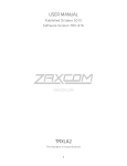
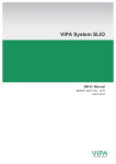
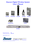
USER MANUAL
Published July 2015
Software Version 1.67
IFB200
ZaxNet Remote Control. Reinvented
1
HOME SCREEN .............................................................................................................................................. 6
ALTERNATE HOME SCREEN........................................................................................................................................... 6
HOME SCREEN OPERATIONS ......................................................................................................................................... 7
MAIN MENU ................................................................................................................................................. 8
ENTERING AND NAVIGATING THE MAIN MENU................................................................................................................ 8
EXITING THE MAIN MENU ............................................................................................................................................ 8
REMOTE GAIN ADJUST ................................................................................................................................................ 8
Adjusting the TRX transmitter gain remotely .................................................................................................... 8
UNIT CODE SELECT ..................................................................................................................................................... 8
REMOTE FREQUENCY ADJUST ....................................................................................................................................... 9
Adjusting the TRX transmitter frequency remotely........................................................................................... 9
REMOTE POWER MODE ADJUST ................................................................................................................................. 10
PLAYBACK CONTROL.................................................................................................................................................. 11
Playing back from the transport page ............................................................................................................. 11
TIME CODE ROUTING ................................................................................................................................................ 11
TIME CODE FRAME RATE SELECT ................................................................................................................................. 11
IFB AUDIO ADJUST ................................................................................................................................................... 11
IFB200 LOCK PAGE .................................................................................................................................................. 12
EXTENDED MENU.........................................................................................................................................13
ENTERING AND NAVIGATING THE EXTENDED MENU ....................................................................................................... 13
EXITING THE EXTENDED MENU ................................................................................................................................... 13
1K NOTCH FILTER ..................................................................................................................................................... 13
RECORD FORMAT ..................................................................................................................................................... 13
IFB TRANSMIT POWER .............................................................................................................................................. 13
IFB MODE............................................................................................................................................................... 14
IFB VOTING ENABLE ................................................................................................................................................. 14
ZAXNET RECEIVE FREQUENCY SET ............................................................................................................................... 14
ZAXNET TRANSMIT FREQUENCY SET ............................................................................................................................ 14
TRANSMITTER REMOTE ROLL ENABLE .......................................................................................................................... 15
POWER ROLL ........................................................................................................................................................... 15
IFB DROPOUT COMPENSATOR .................................................................................................................................... 15
POWER-UP MODE .................................................................................................................................................... 15
SD CARD FORMAT .................................................................................................................................................... 16
TC JAM MODE SELECT .............................................................................................................................................. 16
TIME CODE SOURCE .................................................................................................................................................. 16
MUTE TIME CODE TRANSMISSION UNTIL JAMMED ........................................................................................................ 17
GROUP ID SELECT ..................................................................................................................................................... 17
AUDIO INPUT SELECT................................................................................................................................................. 17
MINIMUM FREQUENCY ............................................................................................................................................. 17
MAXIMUM FREQUENCY ............................................................................................................................................. 18
ALLOW IFB REMOTE CONTROL ................................................................................................................................... 18
ERX SOFTWARE UPDATE ........................................................................................................................................... 18
AUTOMATIC RECORD ON BOOT UP.............................................................................................................................. 18
INPUT PHASE INVERT................................................................................................................................................. 19
HOME SCREEN TIME CODE DISPLAY............................................................................................................................. 19
BACKLIGHT TIMER..................................................................................................................................................... 19
ENCRYPTION MENU HIDE .......................................................................................................................................... 19
ENCRYPTION CODE SET .............................................................................................................................................. 20
2
MEDIA .........................................................................................................................................................21
MEDIA CAPACITY ...................................................................................................................................................... 21
RECORDING FORMAT ................................................................................................................................................ 21
FIRMWARE ..................................................................................................................................................22
UPDATING THE IFB200 FIRMWARE ............................................................................................................................. 22
UPDATING ERX FIRMWARE - USING THE IFB200 ........................................................................................................... 22
WIRING DIAGRAMS......................................................................................................................................23
BALANCED LINE LEVEL ANALOG IN............................................................................................................................... 23
AES DIGITAL IN ........................................................................................................................................................ 23
AUDIO OUT ............................................................................................................................................................. 23
12 VOLT DC POWER ................................................................................................................................................. 23
PRODUCT SUPPORT .....................................................................................................................................24
SPECIFICATIONS ...........................................................................................................................................25
ZAXCOM WARRANTY POLICY AND LIMITATIONS...........................................................................................26
3
Zaxcom IFB200
IFB200 Layout
IFB200
1
4
2
3
5
6
7
1. INC Key
• Increases the parameters of a menu item.
• From the home screen will change the transport commands of the corresponding transmitter.
2. LCD Display
3. Menu Key
• Press it to access the menu and to advance to the next menu item.
• Hold while powering up to access the Extended Menu.
4. DEC / Stop Key
• Decreases the parameters of the menu items.
• From the home screen will change the transport commands of the corresponding transmitter.
5. Micro SD Card Slot
To insert a Micro SD card, turn the card so the finger contacts are facing up towards the LCD screen
and down toward the slot. Insert the card into the slot and press it down until you hear a slight click.
To remove it, press the card in until you hear the same click again.
6. Power Switch
7. Antenna Connector - ZaxNet
4
Zaxcom IFB200
IFB200 Layout
1
5
2
3
4
6 7
1. Audio In Connector - TA5M
This connector will be used to input both analog and digital audio.
• Analog audio is two channels balanced line level.
• Digital audio is an AES pair.
2. Audio Out - 3.5mm (summed to mono on tip of a TRS)
• When in playback the playback audio from the card will be outputted.
• When in transmit mode the inputted audio with be outputted.
• When in receive mode the ZaxNet received audio will be outputted. If there is no ZaxNet
audio present the inputted audio will be outputted.
• When recording the inputted audio will be outputted. When recording in receive mode the
ZaxNet received audio will be outputted.
3. Time code IN/OUT - BNC
The BNC is menu selectable to be used as a time code input or output.
4. DC Power Input - Switchcraft 761 connector.
5. Analog input trim adjust - Channel 1 ( Left )
6. Analog input trim adjust - Channel 2 ( Right )
7. Audio out level adjust
5
Zaxcom IFB200
Home Screen
Home Screen
ZaxNet
Frequency
Recorder
Status
2.404
ZaxNet TRX
Status
STOP STOP
Input Audio Meter
Meter
Indications
-20, -10, 0 dBFS
Frequency
Displays the ZaxNet transmit / receive frequency that the IFB200 is operating on.
Recorder Status
Displays the transport status of the internal audio recorder. When a valid time code signal is being received
this will flash “JAM”. When a formatted card is inserted the approximate record time left on the card will also
flash.
ZaxNet TRX Transport Status
Displays the transmit commands being sent to the transmitters. When in RX mode this will become the status
of the internal recorder.
• REC - TRX record commands will be sent.
• - - - - - Is displayed when the IFB200 is not sending any commands.
• STOP - TRX recording / playback is stopped.
• PLAY - TRX playback commands will be sent.
Please note that this is the order of the commands as they appear in the IFB200. So for example to go from
REC to PLAY the DEC key will need to be presses 3 times and to go from PLAY to STOP the INC key will be
pressed once.
Input Audio Meter
Displays the audio modulation of the inputted signal.
• When the record format is set to MONO one meter will be displayed.
• When in receive mode the meter will display the received audio.
Alternate Home Screen
If the HOME TC DISPLAY menu is set to ON then the frequency will be replaced with the timecode and the
record status is moved to the lower left corner.
01:02:34:01 - - - STOP
I I I
Home Screen with time code
6
Zaxcom IFB200
Home Screen
Home Screen Operations
From the home screen pressing the INC or DEC key will cycle through the TRX control commands in order. If a
formatted card is inserted the internal recorder will follow this sequence. For example if you send a record
command to the TRX the internal recorder will go into record as well.
The IFB200 will boot up to “- - - -“ mode where no command is being sent. Press INC and REC will be displayed
and a record command will be sent to the TRX and will put the internal recorder into record mode. To stop,
press the DEC key twice. The IFB200 will cycle through “- - - -“ then to STOP. Playback would be one more
press of the DEC key.
7
Zaxcom IFB200
Main Menu
Main Menu
Entering and Navigating the Main Menu
• Press the MENU key to enter the menu.
• To advance to the next menu press the MENU key.
Exiting the Main Menu
To exit the menu at any time press and hold the MENU key for 1.5 seconds.
Remote Gain Adjust
This menu will only appear if IFB mode is set to TX (transmit)
REMOTE GAIN
GROUP 01 UNIT001
The remote gain menu adjusts the gain, via ZaxNet, of the TRX transmitter that has the same group and unit
code displayed if “ALL” is selected for the unit code each TRX transmitter in that group will be adjusted
simultaneously. If the TRX is not in range of the ZaxNet signal, the gain command will have to be repeated once
the transmitter comes back into range.
Adjusting the TRX transmitter gain remotely
• Press the INC key to increase the gain. The display will show”++” in the top right hand corner as the gain is
being adjusted.
• Press the DEC key decrease the gain. The display will show”- -” in the top right hand corner as the gain is
being adjusted.
• Each key press will alter the gain by 2dB.
Unit Code Select
REMOTE CONTROL
UNIT CODE = ALL
Each TRX transmitter can be assigned a specific unit code. That unit code allows for that specific transmitter to
be controlled individually from the IFB200. This menu allows for the unit code to be changed so an individual
transmitter can be controlled. If “ALL” is selected multiple transmitters, in the same group, can be adjusted at
the same time. The unit code can be set to any number from 1 to 200 or “ALL” can be selected - to control all
transmitters at the same time.
Please note that if the unit code is changed pressing the MENU key will navigate back to the remote gain menu.
If no changes are made to the unit code pressing the MENU key will advance to the next menu item.
8
Zaxcom IFB200
Main Menu
Remote Frequency Adjust
This menu will only appear if IFB mode is set to TX (transmit)
REMOTE CH 548.0
UNIT CODE = 1
The remote frequency adjust menu is where the frequency of the transmitter that is being controlled is changed
from. If the unit code is set to ALL “WARNING” will be displayed and the frequencies cannot be changed. This is
because if ALL is selected all transmitters will be re-tuned to the same frequency.
Adjusting the TRX transmitter frequency remotely
•
•
•
•
•
In the unit code menu set the unit code for the transmitter to be adjusted.
Press the INC key to increase the frequency.
Press the DEC key to decrease the frequency.
Pressing the INC or DEC key will change the frequency by .1 MHz
Pressing and holding INC or DEC the key will change the frequency by 1MHz.
9
Zaxcom IFB200
Main Menu
Remote Power Mode Adjust
This menu will only appear if IFB mode is set to TX (transmit)
REMOTE POWER MODE
0: POWER = ON
The remote power mode menu allows for the RF power setting of the TRX transmitters to be adjusted.
The TRX transmitters have three selectable power settings:
• NORMAL - The transmitters are at full transmitting power.
• WAKE - If a TRX transmitter is set to REMOTE STANDBY it will power up to a non-transmitting low power
mode and will use approximately 25% of the power of normal operations. A wake command will bring that
transmitter to full power.
To use wake mode set the TRX transmitters BOOT UP MODE to REMOTE STANDBY. Then when the
transmitter powers up, it will remain in standby mode until it receives the wake command to bring it to
full power. Once the TRX is awoken the only way for it to go back into standby mode is by a power cycle.
• LOW 2 - Low 2 disables the RF power amplifier, RF board and microphone pre-amp on the TRX
transmitter. In LOW 2 mode the transmitter will save approximately 50% of the power of normal
operations. A transmitter can be put into or taken out of LOW 2 as often as desired when selected in this
menu.
Settings:
0: POWER=ON – Normal operation - the TRX will be fully powered ON
1: POWER=ON – Normal operation (same as 0) filler to prevent accidental power setting adjustment.
2: POWER=ON – Normal operation (same as 0) filler to prevent accidental power setting adjustment.
3: POWER=ON – Normal operation (same as 0) filler to prevent accidental power setting adjustment.
4: POWER=ON – Normal operation (same as 0) filler to prevent accidental power setting adjustment.
5: POWER=WAKE – Selected to wake a transmitter to full power mode from remote standby mode.
6: POWER=LOW2 – Selected to put a transmitter into and out of low power mode. A transmitter can come
in and out of LOW 2 mode as needed. When in LOW 2 mode “LOW 2” will be displayed on the
transmitter’s home screen. Please note LOW 2 will not disable recording but audio will be muted. Once
the TRX power is set to Low 2 the IFB200 can be powered down. Then when the IFB200 is powered up all
transmitters being controlled will automatically come up to full power since the IFB200 will always boot up
to the 0 Power setting.
Please note if the TRX transmitter is not in range of the ZaxNet signal, the power setting command will have
to be repeated once the transmitter comes back into range.
10
Zaxcom IFB200
Main Menu
Playback Control
PLAY 01:02:34:01
001
Recorded files can be played back from this page.
The top line displays the current mode of the recorder: REC, PLAY or STOP followed by the time code.
The bottom line contains the current segment number and the audio level.
Playing back from the transport page
•
•
•
•
•
•
Pressing the INC key while stopped will play the segment that is displayed.
Pressing the INC key while playing back will jump ahead approximately 2 minutes.
Press and holding the INC key will advance to the next segment.
Pressing the DEC key while playing back will stop the playback.
Holding the DEC key while playing back will take you to the start of that segment.
Pressing the DEC key while stopped will jump back a segment.
Time Code Routing
TC CONNECTOR:
OUTPUT
The time code routing menu sets the function of the BNC time code connector.
• OUTPUT - TheIFB200 will output time code on the BNC connector.
• INPUT - The IFB200 will receive time code on the BNC connector.
Time Code Frame Rate Select
TIMECODE 23.98
GEN 01:02:34:01
The time code frame-rate that will be recorded and transmitted over ZaxNet is set from this menu.
The IFB200 will lock to and transmit all standard time code frame rates.
• 23.98, 24, 25, 29.97DF, 29.97DF, 30 DF, 30 NDF
IFB Audio Adjust
IFB TX MIX:
LEFT AND RIGHT
The IFB audio mix sets what audio will be transmitted from the IFB200 via ZaxNet.
• RIGHT ONLY - Right inputted audio only will be transmitted.
• LEFT ONLY - Left inputted audio only will be transmitted.
• LEFT AND RIGHT - Both Left and right audio will be summed to mono and transmitted.
11
Zaxcom IFB200
Main Menu
IFB200 Lock Page
LOCK 5
LOCKED 01:02:34:01
Countdown clock starting at 5 seconds
After the transmitter locks
This page enables a lock function to prevent any accidental key presses.
When stopping on this page a countdown clock will begin. After 5 seconds the keys will lock and the
display will indicated that it is LOCKED followed by the time code.
If you exit this screen before the 5 seconds is up the IFB200 will not lock.
To unlock the IFB200
• Simultaneously press the MENU and INC keys.
Or
• Powering down the unit will clear the lock.
12
Zaxcom IFB200
Extended Menu
Extended Menu
Entering and Navigating the Extended Menu
•
•
Press and hold the MENU key while powering up the unit.
Pressing the MENU key will advance to the next menu item.
Exiting the Extended Menu
Hold down the MENU key to get back to the extended menu home page then press the INC key.
Or
• Cycle the power
•
1K Notch Filter
1K NOTCH FILTER
OFF
The 1K notch filter is used to eliminate the 1 Kilohertz tone from being outputted to an ERX receiver.
This menu enables/disables the 1 Kilohertz notch filter.
Record Format
RECORD FORMAT:
STEREO
This menu adjusts the record format of the internal recorder. Please note that any changes to the record format
will require the IFB200 to be rebooted.
• US MONO - The IFB200 will record both inputs summed to mono.
• STEREO -The IFB200 will record both inputs independently.
• US MONO-R -This setting is not applicable on the IFB-200
IFB Transmit Power
This menu will only appear if IFB mode is set to TX (transmit)
IFB TX POWER: 5
The IFB transmit power of the IFB200 ZaxNet transmitter is set from this menu.
13
Zaxcom IFB200
Extended Menu
IFB Mode
IFB MODE: TX
This menu sets if the IFB200 will transmit ZaxNet or receive ZaxNet. Please note that is the IFB200 is set to
receive the TRX transmitter control items in the main menu will not be available.
• OFF - The ZaxNet transceiver is turned off and the IFB200 will not transmit or receive ZaxNet.
• RX - The IFB200 will receive ZaxNet IFB audio and time code.
• TX - The IFB200 will send ZaxNet commands, IFB audio and time code.
IFB Voting Enable
This menu will only appear if IFB mode is set to RX (receive).
IFB VOTING
NORMAL (OFF)
This menu enables / disables the IFB Voting function when the IFB200 is being used to receive ZaxNet.
The purpose of IFB voting is to allow the IFB200 to choose, and switch to, the stronger signal from two
different ZaxNet transmitters. IFB voting allows a second IFB transmitter to be placed at a different location
then the ZaxNet receiver will choose the stronger of the two signals to listen to.
Please note that when using IFB voting the second ZaxNet transmitting frequency must be set to exactly
2MHz higher than the first ZaxNet transmitter.
ZaxNet Receive Frequency Set
RXFREQ: 2.403
When the IFB200 is receiving a ZaxNet signal:
RXFREQ: 2.403 RX
SIGNAL: 28
ZaxNet receive frequency and RX shows that ZaxNet is being received
ZaxNet signal strength meter
Signal strength
This menu is where the ZaxNet receive frequency of the IFB200 is set. There are 72 selectable ZaxNet
frequencies from 2.403GHz – 2.473GHz
ZaxNet Transmit Frequency Set
IFB TX CH: 2.420
This is where the ZaxNet transmit frequency of the IFB200 is set. The ZaxNet transmit frequency is the
frequency that the IFB200 will broadcast remote commands, time code and ZaxNet audio on. There are 72
choices of frequencies from 2.403GHz – 2.473GHz.
14
Zaxcom IFB200
Extended Menu
Transmitter Remote Roll Enable
TRANSMIT TPMODE
ON
The transmitter TP mode menu enables the TRX transmitters to follow the record and stop commands of the
IFB200. If this is set to ON and if recording on the IFB200 is triggered all TRX transmitters that are being
controlled from the IFB200 will begin to record.
Power Roll
POWER ROLL:
OFF
Power roll allows a TRX transmitter to stay at lower transmit power setting to conserve battery power when
not recording. Then when record the transmitter will increase its output power. Please note to use this feature
the TRX transmitter will need to have power roll and it will need to be enabled in the TRX transmitter.
• OFF – Power roll is disabled.
• DIVA TRIGGER – When a Zaxcom recorder begins to record the ZaxNet information that is embedded in
the time code will cause the transmitter to go to full transmit power. To use this feature the IFB200 would
need to be hard wired to the time code out.
• RECORD TRIGGER – When the IFB200 receives running time code, in a record run situation, the IFB200 will
send a command to the TRX transmitter to go to full power.
IFB Dropout Compensator
This menu will only appear if IFB mode is set to RX (receive)
IFB DROPOUT
COMPENSATOR ON
The IFB dropout compensator menu enables /disables the ZaxNet IFB drop out compensator.
When the drop out compensator is enabled, and if there is a brief drop out in the received ZaxNet audio, the
drop out compensator will replace the drop out with a bit of the surrounding audio so the audio will match
and there will be no audible drop out.
Power-Up Mode
POWER UP MODE:
LOCKED
The power up mode menu sets what happens to the keys on the IFB200 after boot-up.
• LOCKED – After boot-up has completed, the IFB200 will automatically go into lock mode and the keys will
be locked to prevent accidental changes to the settings.
• UNLOCKED – After boot-up the keys will remain unlocked. When in this mode the IFB200 can always be
locked by going in to the lock screen in the main menu and wait 5 seconds.
To unlock the keys at any time - simultaneously press the MENU and INC keys.
15
Zaxcom IFB200
Extended Menu
SD Card Format
This menu will only appear if a card was inserted prior to booting up
PRESS UP KEY 5X
TO ERASE CARD
The Micro SD card is erased and formatted from this menu. Please note that all cards need to be formatted
prior to use and only cards formatted in the IFB200 will work.
Before formatting the card, you may want to name the transmitter– if so please see the transmitter naming
section in this manual.
Formatting an SD Card:
1. With the power off, insert the memory card into the media slot with the card label to the back of the
unit. Press the card all the way in until it “clicks”.
2. Power up the IFB200 while holding the menu key to enter the extended menu.
3. Advance to this menu.
4. Press the INC key 5 times.
5. FORMATTING FAT 32 will be displayed.
6. In a few minutes, depending on the size of the card either “SUCCESS” or “FORMAT FAILED ERROR” will be
displayed.
7. If “SUCCESS” appears power cycle the IFB200.
8. If “FORMAT FAILED ERROR” try to re-format the card, if it fails again it is not advised to use that card.
TC Jam Mode Select
TC JAM MODE:
AUTO-JAM NORMAL
If record run time code is being used this menu controls if the IFB200 will automatically go into record when it
receives a record run time code.
• AUTO-JAM NORMAL– The IFB200 will continuously jam time code and will not automatically go into
record.
• AUTO-LOAD REC RUN – The IFB200 will start and stop recording when receiving record run time code.
In auto-load the IFB200 will go into record when detecting rolling time code. And will stop when the time
code stops. If time code is lost the unit will not stop but will continue in whatever state it was in until the
time code signal is restored.
Time Code Source
TC SOURCE:
BNC CONNECTOR
This menu selects how the IFB200 will receive its time code.
• IFB (RF) – The IFB200 will receive time code via ZaxNet being broadcast from another ZaxNet transmitter.
• BNC Connector – If BNC is selected and the TIME CODE CONNECTOR menu is set to “INPUT” the
IFB200 will receive time code via the BNC connector.
16
Zaxcom IFB200
Extended Menu
Mute Time Code Transmission Until Jammed
MUTE TC UNTIL
JAMMED: OFF
If mute time code is set to ON the ZaxNet transmitter will not broadcast time code over ZaxNet until it
receives and jams its own internal time code generator. This prevents the ZaxNet from sending incorrect
time code to another device.
Group ID Select
REMOTE CONTROL
GROUP CODE = 1
Group ID sets the IFB200 ZaxNet transmitter to a “GROUP”.
So for example a TRX transmitter set to Group 1 will be controlled by a ZaxNet transmitter set to Group 1 and
a group 2 transmitter will be controlled by a Group 2 ZaxNet transmitter. This allows a group of transmitters to
be controlled without affecting others. This will also help if two or more people on set are sending ZaxNet
commands each person will be independent and won’t interfere with each other. Most users leave this set to
1 on all of their Zaxcom products. Group codes can be set from 1 to 99.
Audio Input Select
INPUT: ANALOG
The audio input select sets what audio the IFB200 will input.
• ANALOG – Used when inputting an analog audio signal.
• DIGITAL L - Used when Inputting a digital signal on pins 1, 2, 3 on the TA5 connector.
• DIGITAL R - Used when inputting a digital signal on pins 1, 4, 5 on the TA5 connector.
Minimum Frequency
MIN FREQ: 512.0
(TVCHAN MIN 21)
This menu sets the lowest UHF frequency that the IFB200 will cycle to when remote controlling TRX
transmitters. This eliminates having to cycle through frequencies that are out of the working frequency range
of the TRX transmitters that are being controlled.
17
Zaxcom IFB200
Extended Menu
Maximum Frequency
MAX FREQ: 698.0
(TVCHAN MIN 51)
This menu sets the highest UHF frequency that the IFB200 will cycle to when remote controlling TRX
transmitters. This eliminates having to cycle through frequencies that are out of the working frequency range
of the TRX transmitters that are being controlled.
Allow IFB Remote Control
This menu will only appear if IFB mode is set to RX (receive)
ALLOW IFB REMOTE
CONTROL:
ON
IFB remote control allows the IFB200 to receive record commands from another ZaxNet transmitter.
ERX Software Update
PRESS TO SEND
ERX PROG FILE
This menu is used to update the software on a Zaxcom ERX receiver.
To Update the ERX Software
1.
2.
3.
4.
5.
6.
Format a micro SD card in the IFB200 and with a computer delete the “delete.me” file.
Copy the ERX software onto the card and place the card in the IFB200.
Set up your ERX to receive software (see the ERX manual).
Power up the IFB200 and advance to this menu.
Press the INC key.
The IFB200 will begin to transmit the software and will continuously be resent until manually stopped.
Automatic Record On Boot up
RECORD ON BOOTUP
ON
Record after boot up will allow the IFB200 to automatically go into record after it boots up.
• ON - The IFB200 will automatically start to record after it boots up.
• OFF - The IFB200 will wait for a manual record trigger to start recording.
18
Zaxcom IFB200
Extended Menu
Input Phase Invert
PHASE INVERT CH2
OFF
If set to ON the phase of the channel 2 (Right) audio input on the TA5 connector will be inverted to correct for
a phasing issue with the input cable.
Home Screen Time Code Display
HOME TC DISPLAY:
ON
This menu will determine if the IFB200 will display its ZaxNet transmit frequency or time code on the home
screen.
01:02:03:01 STOP
RX
2.420
RX
STOP
ON - The home screen will display the time code and the recorder status on
the top with the ZaxNet status and audio meters on the bottom. When
recording the ZaxNet status will also flash the time remaining on the card.
OFF - The home screen will display the ZaxNet transmit frequency, ZaxNet
status and recorder status on the top with the audio meters on the bottom.
When recording the ZaxNet status will also flash the time remaining on the
card.
Backlight Timer
BACKLIGHT TIMER
ALWAYS ON
The backlight menu sets the function of the backlight. Please note that the power draw of the backlight is very
negligible and will not be putting a high demand on the battery
• OFF - The backlight will remain off.
• ALWAYS ON - The backlight will always stay on.
• 1 - 29 seconds - The backlight will remain on after the last button push for the selected time.
Encryption Menu Hide
ENCRYPTION MENU:
HIDDEN
This menu allows for the encryption menu to be hidden preventing accidental changes.
• HIDDEN -The encryption menu does not appear when cycling through the menu settings.
• ON - The encryption menu will appear and can be changed.
19
Zaxcom IFB200
Extended Menu
Encryption Code Set
ID1:000 ID0:000
For normal un-encrypted operations all six numbers should be set to zero. If the encryption code is set to
any number other than all zeroes, the transmitted audio will be encrypted and can only be listened to if
the receiver has the matching encryption code entered. When a receiver is getting an audio signal, and
the codes do not match, all that will be heard is white-noise or silence.
These two sets of numbers are formed into a single six-digit encryption code which provides a total of
16,777,216 possible combinations.
To adjust the encryption code
1. Momentarily press the MENU key to advance to the next character.
2. To change the designated character, press the INC or DEC key.
3. To exit this page, press and hold the MENU key for 1 second.
20
Zaxcom IFB200
Record Media
Media
While any capacity card will work we recommend using a 4GB Micro SD card. We also recommend that you
buy a brand name card such as Transcend, SanDisk. You should always buy your cards from a reputable
dealer because counterfeit cards exist and can cause recording issues.
We also recommend that you test your card before taking them out into the field.
The following is a simple test procedure to determine if the card will function correctly:
1. Format the card in the IFB200.
2. Power cycle the unit.
3. Record at least 20 minutes of audio to a card with no time code source feeding the IFB200.
4. Look at the Main Screen it should still be recording in segment #1.
Please note the transmitter will NOT record onto the card if:
• The card was not inserted when the IFB200 was powered up.
• If the card was removed while the power was on.
• If LOW BATTERY is being displayed.
Media Capacity
The IFB200 can use Micro SD cards, ranging in size from 128 MB to 16 GB. While any size card will work we
recommend using 4GB cards. Please note that regardless of the size of the card the onboard recorder will
only be able to record up to 254 individual segments on any given card.
Available recording times are as follows:
128 MB
Available
Recording Time
45 minutes
256 MB
1.5 hours
512 MB
3 hours
1 GB
6 hours
2 GB
12 hours
4 GB
24 hours
8 GB
48 hours
16 GB
96 hours
Media Size
Recording Format
The media card is formatted using a FAT32 file system. While recording, the unit places all recorded audio in a
single file on the media.
The files generated will be recorded as a .zax file and can only be recognized by Zaxcom’s ZaxConvert
program. Using ZaxConvert will convert the file to a Broadcast Wave or MP3 file. This utility is available to
anyone for free from the Zaxcom website http://www.zaxcom.com/software-updates
21
Zaxcom IFB200
Firmware
Firmware
Each IFB200 is shipped with the latest firmware version installed. As newer firmware becomes available, it can
be downloaded from the Zaxcom website:
http://www.zaxcom.com/software-updates
Newer version of beta software may be found on the Zaxcom forums:
http://www.zaxcom.com/forum
Each time the IFB200 is powered up, the firmware version number is displayed briefly on the LCD screen.
Pressing the DEC key during the boot up will slow down the screen to allow easier viewing of the information.
Updating the IFB200 Firmware
1.
2.
3.
4.
5.
6.
7.
Format a micro SD card in the IFB200 and with a computer delete the “DELETE.ME” file.
Download the new firmware from the Zaxcom website and load it onto the formatted card.
Insert the card into the IFB200.
Simultaneously hold down the INC and DEC keys while powering up the IFB200
The screen will display “BURN ROM” with the version of firmware that is loading.
From power up to “DONE” will take about 30 seconds.
Upon completion, cycle the power.
WARNING: Do not power down the unit during the update process, and before updating the software be sure
to insert a fresh set of batteries. If the unit should lose power during the upgrade, it will need to be sent back to
Zaxcom for repair.
Updating ERX Firmware - using the IFB200
1.
2.
3.
4.
5.
Format a micro SD card in the IFB200 and with a computer delete the “DELETE.ME” file.
Download the new firmware from the Zaxcom website and load it onto the formatted card.
Insert the card into the IFB200.
Insert a fresh set of batteries into each ERX.
Check that the ERX is set to the same ZaxNet frequency that the IFB200 is set to. Check that the GROUP ID is
set the same in both the IFB and ERX. And make sure encryption is shut off.
6. Boot up the ERX while holding the menu key to get to the ERX EXTENDED menu.
7. On the ERX press the menu key until the software update page is displayed.
8. Press the INC key on the ERX 5 times “WAITING FOR PROGRAM” will be displayed.
9. At the IFB200:
• Press and hold the MENU key while powering up to enter the extended menu.
• Advance to the “Send ERX Program” menu and press the INC Key.
• The IFB200 will indicate that it found the program and has started sending it. The IFB200 will continue to
transmit the software until manually stopped.
10. The ERX should indicate its progress after a few seconds.
11. When the ERX has been updated the screen will display “SUCCESS”.
12. Power cycle both the ERX and the IFB200.
WARNING: Do not power down the unit during the update process, and before updating the software be sure
to insert a fresh set of batteries. If the unit should lose power during the upgrade, it will need to be sent back to
Zaxcom for repair.
22
Zaxcom IFB200
Wiring Diagrams
Wiring Diagrams
Balanced Line Level Analog In
Uses a Switchcraft TA5-F
XLR
Out of Mixer
PIN 1 on both outputs
PIN 2 - Left
PIN 3 - Left
PIN 2 - Right
PIN 3 - Right
TA5
On IFB-200
PIN 1
PIN 2
PIN 3
PIN 4
PIN 5
AES Digital in
Uses a Switchcraft TA5-F
XLR
Out of Mixer
Ground
Signal
Signal
No Connection
No Connection
TA5
On IFB-200
PIN 1
PIN 2
PIN 3
PIN 4
PIN 5
Audio Out
Uses a standard 3.5mm TRS
3.5 mm Audio
Out
SIGNAL
NO CONNECTION
GROUND
TIP
RING
SLEEVE
12 Volt DC power
Uses a Switchcraft 760K
DC Power
In
CENTER PIN
SLEEVE
+
-
23
Zaxcom IFB200
Support
Product Support
Register your product with Zaxcom:
Download the latest Firmware from:
Download the latest User Manuals from:
Submit Technical Questions at:
Submit information for Repair Services at:
Join the Zaxcom User Forum at:
Join the Zaxcom Face Book User Group at:
http://zaxcom.com/support/product-registration/
http://zaxcom.com/support/updates/
http://zaxcom.com/support/updates/
http://www.zaxcom.com/submit-a-technical-question
http://www.zaxcom.com/support/repairs
http://www.zaxcom.com/forum/forum.php
https://www.facebook.com/groups/682199065139938/
24
Zaxcom IFB200
Specifications
Specifications
IFB RF Transmitter
RF Power Output: 10.4 mW
RF Modulation: Digital Spread Spectrum
RF Frequency Range: 2.403 to 2.473 GHz
RF Frequency Step: 0.001 GHz (1 MHz)
RF Bandwidth: 1 MHz
Channel Separation: 1 MHz
Antenna Connector: 50-ohm SMA Female
Connector type reverse SMA
.
IFB Audio Transmitter
Dynamic Range: 103 dB
Distortion: 0.01%
Frequency Response: 20 Hz to 12 kHz
System Group Delay: 10 ms
.
IFB Analog or Digital Audio Input
Connector: TA-5M
Type: Balanced
Level: -10 dBu to +4 dBu
Impedance: 10 k Ω
ADC Bit-depth: 24 bits
ADC Sampling Rate: 32 kHz
.
Timecode Input/Output
Connector: BNC
Input Level Range: 1 to 5V, P-P
Output level 2V P-P
Impedance: 75 Ω
.
Timecode Reader / Generator
Clock Accuracy: 1.54 PPM (1 frame out in 6 hours)
Timecode Type: SMPTE
Timecode Frame Rates: 23.98, 24, 25, 29.97NDF, 29.97DF, 30NDF, 30DF
.
Physical
Weight: 7.3 oz
Dimensions: 3.6″ x 3.23″ x 1.0″
External Power: 8 to 18 VDC @ 180 mA
Internal Power: N/A
Display: Graphic LCD Panel
.
All Specifications subject to change without notice
25
Zaxcom Warranty Policy and Limitations
Zaxcom Inc. values your business and always attempts to provide you with the very best service.
No limited warranty is provided by Zaxcom unless your IFB200 (“Product”) was purchased from an authorized distributer or authorized reseller.
Distributers may sell Product to resellers who then sell Product to end users. Please see below for warranty information or obtaining service. No
warranty service is provided unless the Product is returned to Zaxcom Inc. or a Zaxcom dealer in the region where the Product was first shipped by
Zaxcom.
Warranty Policy
The Product carries a Standard Warranty Period of one (1) year.
NOTE: The warranty period commences from the date of delivery from the Zaxcom dealer or reseller to the end user.
There are no warranties which extend beyond the face of the Zaxcom limited warranty. Zaxcom disclaims all other warranties, express or implied,
regarding the Product, including any implied warranties of merchantability, fitness for a particular purpose or non-infringement. In the United States,
some laws do not allow the exclusion of the implied warranties.
Troubleshooting & Repair Services
No Product should be returned to Zaxcom without first going through some basic troubleshooting steps with the dealer you purchased your gear from.
To return a product for repair service, go to the Zaxcom Repair Services page http://www.zaxcom.com/repairs and fill in your information; there is no
need to call the factory for an RMA. Then send your item(s) securely packed (in the original packaging or a suitable substitute) to the address that was
returned on the Repair Services page. Insure the package, as we cannot be held responsible for what the shipper does.
Zaxcom will return the warranty repaired item(s) via two-day delivery within the United States at their discretion. If overnight service is required, a
FedEx or UPS account number must be provided to Zaxcom to cover the shipping charges.
*Please note a great resource to troubleshoot your gear is the Zaxcom Forum: http://www.zaxcom.com/forum.
Warranty Limitations
Zaxcom’s limited warranty provides that, subject to the following limitations, each Product will be free from defects in material and workmanship and
will conform to Zaxcom’s specification for the particular Product.
Limitation of Remedies
Your exclusive remedy for any defective Product is limited to the repair or replacement of the defective Product.
Zaxcom may elect which remedy or combination of remedies to provide in its sole discretion. Zaxcom shall have a reasonable time after determining
that a defective Product exists to repair or replace a defective Product. Zaxcom’s replacement Product under its limited warranty will be manufactured
from new and serviceable used parts. Zaxcom’s warranty applies to repaired or replaced Product for the balance of the applicable period of the original
warranty or thirty days from the date of shipment of a repaired or replaced Product, whichever is longer.
Limitation of Damages
Zaxcom’s entire liability for any defective Product shall, in no event, exceed the purchase price for the defective Product. This limitation applies even if
Zaxcom cannot or does not repair or replace any defective Product and your exclusive remedy fails of its essential purpose.
No Consequential or Other Damages
Zaxcom has no liability for general, consequential, incidental or special damages. These include loss of recorded data, the cost of recovery of lost data,
lost profits and the cost of the installation or removal of any Product, the installation of replacement Product, and any inspection, testing or redesign
caused by any defect or by the repair or replacement of Product arising from a defect in any Product.
In the United States, some states do not allow exclusion or limitation of incidental or consequential damages, so the limitations above may not apply to
you. This warranty gives you specific legal rights and you may also have other rights, which vary from state to state.
Your Use of the Product
Zaxcom will have no liability for any Product returned if Zaxcom determines that:
• The Product was stolen.
• The asserted defect:
• Is not present,
• Cannot reasonably be fixed because of damage occurring when the Product is in the possession of someone other than Zaxcom, or
• Is attributable to misuse, improper installation, alteration, including removing or obliterating labels and opening or removing external covers
(unless authorized to do so by Zaxcom or an authorized Service Center), accident or mishandling while in the possession of someone other than
Zaxcom.
• The Product was not sold to you as new.
Additional Limitations on Warranty
Zaxcom’s warranty does not cover Product, which has been received improperly packaged, altered or physically abused.
26
Warning: Changes or modifications to this device not expressly approved by Zaxcom Inc. could void the user’s authority to operate the
equipment.
NOTE: This equipment has been tested and found to comply with the limits for a Class B digital device, pursuant to Part 15 of the FCC Rules.
These limits are designed to provide reasonable protection against harmful interference in a residential installation. This equipment generates,
uses, and can radiate radio frequency energy and, if not installed and used in accordance with the instructions, may cause harmful interference
to radio communications. However, there is no guarantee that interference will not occur in a particular installation. If this equipment does
cause harmful interference to radio or television reception, which can be determined by turning the equipment off and on, the user is
encouraged to try to correct the interference by one or more of the following measures:
• Reorient or relocate the receiving antenna.
• Increase the separation between the equipment and receiver.
• Connect the equipment into an outlet on a circuit different from that to which the receiver is connected.
• Consult the dealer or an experienced radio/TV technician for help.
RF Exposure:
This equipment complies with FCC radiation exposure limits set forth for an uncontrolled environment. This equipment is in direct contact with
the body of the user under normal operating conditions. This transmitter must not be co-located or operating in conjunction with any other
antenna or transmitter.
Under Industry Canada regulations, this radio transmitter may only operate using an antenna of a type and maximum (or lesser) gain approved
for the transmitter by Industry Canada. To reduce potential radio interference to other users, the antenna type and its gain should be so chosen
that the equivalent isotropically radiated power (e.i.r.p.) is not more than that necessary for successful communication.
Conformément à la réglementation d'Industrie Canada, le présent émetteur radio peut fonctionner avec une antenne d'un type et d'un gain
maximal (ou inférieur) approuvé pour l'émetteur par Industrie Canada. Dans le but de réduire les risques de brouillage radioélectrique à
l'intention des autres utilisateurs, il faut choisir le type d'antenne et son gain de sorte que la puissance isotrope rayonnée équivalente (p.i.r.e.) ne
dépasse pas l'intensité nécessaire à l'établissement d'une communication satisfaisante.
This radio transmitter (IFB-200) and has been approved by Industry Canada to operate with the antenna types listed below with the maximum
permissible gain and required antenna impedance for each antenna type indicated. Antenna types not included in this list, having a gain greater
than the maximum gain indicated for that type, are strictly prohibited for use with this device.
2.4GHz Quarter Wave Whip Antenna, 2.2dBi gain, 50 Ohms
Le présent émetteur radio (IFB200) a été approuvé par Industrie Canada pour fonctionner avec les types d'antenne énumérés ci-dessous et ayant
un gain admissible maximal et l'impédance requise pour chaque type d'antenne. Les types d'antenne non inclus dans cette liste, ou dont le gain
est supérieur au gain maximal indiqué, sont strictement interdits pour l'exploitation de l'émetteur.
2.4GHz Quarter Wave Whip Antenna, 2.2dBi gain, 50 Ohms
This device complies with Industry Canada license-exempt RSS standard(s). Operation is subject to the following two conditions: (1) this device
may not cause interference, and (2) this device must accept any interference, including interference that may cause undesired operation of the
device.
Le présent appareil est conforme aux CNR d'Industrie Canada applicables aux appareils radio exempts de licence. L'exploitation est autorisée aux
deux conditions suivantes : (1) l'appareil ne doit pas produire de brouillage, et (2) l'utilisateur de l'appareil doit accepter tout brouillage
radioélectrique subi, même si le brouillage est susceptible d'en compromettre le fonctionnement.
27