1
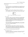
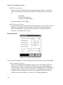
ZETRON
RTU Configuration Utility
User’s Manual
Part No. 025-9445C
Copyright © 2008 Zetron, Inc. All rights reserved. This publication is protected by copyright; information in this document is subject to
change without notice. Zetron and the Zetron logo are registered trademarks of Zetron, Inc. Other company names and
product names may be trademarks or registered trademarks of their respective owners. This publication may not be
reproduced, translated, or altered, in whole or in part, without prior written consent from Zetron, Inc.
SOFTWARE LICENSE
The Zetron software described in this manual is subject to the terms and conditions of
Zetron’s Software License Agreement, a copy of which is contained on the product
distribution media or otherwise provided or presented to buyer. Installation and/or use of the
Zetron software constitutes acceptance of Zetron’s Software License Agreement.
LIMITED WARRANTY
Buyer assumes responsibility for the selection of the Products and Services to achieve
buyer’s or its customer’s intended results and for the results obtained from the Products and
Services. If buyer has provided Zetron with any requirements, specifications or drawings, or
if Zetron provides buyer with such materials, such materials are provided solely for buyer’s
convenience and shall not be binding on Zetron unless agreed contractually by Zetron.
UNLESS AGREED CONTRACTURALLY BY ZETRON, ZETRON DOES NOT
WARRANT THAT THE PRODUCTS OR SERVICES WILL MEET BUYER'S OR ITS
CUSTOMER’S REQUIREMENTS OR SPECIFICATIONS OR THAT OPERATION OF
THE PRODUCTS WILL BE UNINTERRUPTED OR ERROR FREE. SUBJECT TO THE
LIMITATIONS SET FORTH BELOW, Zetron warrants that all Zetron Products and
Services will be free from material defects in material and workmanship for one year from
date of shipment or performance of the Services (except where indicated otherwise in the
Zetron Price Book). For buyer’s convenience, Zetron may purchase and supply additional
items manufactured by others. In these cases, although Zetron’s warranty does not apply,
buyer shall be the beneficiary of any applicable third party manufacturer’s warranties, subject
to the limitations therein. Zetron's warranty covers parts and Zetron factory labor. Buyer
must provide written notice to Zetron within the warranty period of any defect. If the defect
is not the result of improper or excessive use, or improper service, maintenance or
installation, and if the Zetron Products or Zetron Accessories have not been otherwise
damaged or modified after shipment, AS ZETRON'S SOLE AND EXCLUSIVE LIABILITY
AND BUYER'S SOLE AND EXCLUSIVE REMEDY, Zetron shall either replace or repair
the defective parts, replace the Zetron Products or Zetron Accessories, reperform the Services
or refund the purchase price, at Zetron's option, after return of such items by buyer to Zetron.
Shipment shall be paid for by the buyer. No credit shall be allowed for work performed by
the buyer. Zetron Products or Zetron Accessories which are not defective shall be returned at
buyer's expense, and testing and handling expense shall be borne by buyer. Out-of-warranty
repairs will be invoiced at the then - current Zetron hourly rate plus the cost of needed
components. THE FOREGOING WARRANTY AND THE THIRD PARTY
MANUFACTURER'S WARRANTIES, IF ANY, ARE IN LIEU OF ANY AND ALL
OTHER WARRANTIES EXPRESSED, IMPLIED OR ARISING UNDER LAW,
INCLUDING, BUT NOT LIMITED TO, THE IMPLIED WARRANTIES OF
MERCHANTABILITY, NON-INFRINGEMENT AND FITNESS FOR A PARTICULAR
PURPOSE.
LIMITATION OF LIABILITY
Zetron makes no representation with respect to the contents of this document and/or the
contents, performance, and function of any accompanying software. Further, Zetron reserves
the right to revise this document or the accompanying software and to make changes in it
from time to time without obligation to notify any person or organization of such revisions or
changes.
This document and any accompanying software are provided “As Is.” ZETRON SHALL
NOT UNDER ANY CIRCUMSTANCES BE LIABLE TO BUYER OR ANY THIRD
PARTY FOR ANY INCIDENTAL, SPECIAL, CONSEQUENTIAL OR INDIRECT LOSS
OR DAMAGE ARISING OUT OF OR CONNECTED WITH BUYER’S PURCHASE OR
USE OF ZETRON PRODUCTS, ZETRON ACCESSORIES OR ZETRON SERVICES. IN
NO EVENT SHALL ZETRON’S LIABILITY (WHETHER FOR NEGLIGENCE OR
OTHER TORT, IN CONTRACT OR OTHERWISE) EXCEED THE PRICE PAID TO
ZETRON FOR THE ZETRON PRODUCTS, ZETRON ACCESSORIES OR ZETRON
SERVICES.
IP networks by their nature are subject to a number of limitations, such as security,
reliability, and performance. Anyone using non-dedicated IP networks, such as shared WANs
or the Internet, to connect to any Zetron Products or systems should consider and is
responsible for these limitations.
TRADEMARKS
Zetron is a registered trademark of Zetron, Inc.
All other product names in this document are trademarks or registered trademarks of their
respective owners.
Table of Contents
1. INTRODUCTION
OVERVIEW ............................................................................................................... 1-1
Device Configuration...................................................................................... 1-1
Data Logging (RTU Only).............................................................................. 1-1
Upgrade Device Firmware.............................................................................. 1-2
FEATURES ................................................................................................................ 1-2
HARDWARE REQUIREMENTS.............................................................................. 1-2
USING THE DOCUMENTATION ........................................................................... 1-3
Who Should Read This Manual? .................................................................... 1-3
Using This Manual.......................................................................................... 1-3
Additional Information ................................................................................... 1-3
Getting Help.................................................................................................... 1-4
2. INSTALLING THE CONFIGURATION UTILITY
FROM A CD-ROM DRIVE ....................................................................................... 2-1
REMOVING THE PROGRAM ................................................................................. 2-2
3. SETTING UP COMMUNICATIONS
DIRECT RS-232 CONNECTION.............................................................................. 3-1
Ports and Cables.............................................................................................. 3-2
Configuration Utility Settings for Direct Connection..................................... 3-3
VIA RADIO................................................................................................................ 3-4
Connections..................................................................................................... 3-4
Configuration Utility Settings for Radio Communications ............................ 3-4
VIA PHONE MODEM............................................................................................... 3-5
Connections..................................................................................................... 3-5
Configuration Utility Settings for Phone Modem Communications .............. 3-5
TESTING COMMUNICATIONS.............................................................................. 3-9
4. GETTING STARTED
GENERAL TOOLS .................................................................................................... 4-1
Menu Bar ........................................................................................................ 4-1
Toolbars .......................................................................................................... 4-2
Status Bar ........................................................................................................ 4-3
CHANGING YOUR BACKGROUND COLOR ....................................................... 4-4
USING SHORTCUT KEYS....................................................................................... 4-4
ONLINE HELP........................................................................................................... 4-5
5. CONFIGURING A DEVICE
STARTING THE CONFIGURATION FILE............................................................. 5-1
Starting by Reading the Device Configuration............................................... 5-1
Starting by Opening a Previously Saved File ................................................. 5-3
Starting with a New File ................................................................................. 5-4
MODIFYING THE FILE ........................................................................................... 5-4
Cut................................................................................................................... 5-5
Table of Contents
(Continued)
Copy................................................................................................................ 5-5
Paste ................................................................................................................ 5-5
I/O Properties .................................................................................................. 5-5
Module Properties........................................................................................... 5-5
Add/Remove Modules .................................................................................... 5-6
DEVICE INFO............................................................................................................ 5-6
ADD/REMOVE MODULES...................................................................................... 5-8
Technical Note:............................................................................................... 5-9
CORE PROPERTIES ................................................................................................. 5-10
Exception Setup .............................................................................................. 5-14
Real Time Clock ............................................................................................. 5-16
Local Logic Setup ........................................................................................... 5-17
MODBUS Setup (Controller Only) ................................................................ 5-17
CORE INPUTS........................................................................................................... 5-19
Run Time ........................................................................................................ 5-20
Counter............................................................................................................ 5-21
CORE OUTPUTS....................................................................................................... 5-22
DIGITAL I/O .............................................................................................................. 5-24
RELAY OUTPUTS .................................................................................................... 5-27
ANALOG INPUTS..................................................................................................... 5-29
Accumulator Setup.......................................................................................... 5-34
ANALOG OUTPUTS................................................................................................. 5-35
PHONE MODEM....................................................................................................... 5-40
RADIO MODEM........................................................................................................ 5-42
FINISHING AND WRITING TO THE DEVICE...................................................... 5-44
Saving the Configuration File......................................................................... 5-44
Resetting the Configuration File..................................................................... 5-45
Printing the Configuration for a Final Check ................................................. 5-45
Writing the Configuration File to the Device ................................................. 5-45
6. LOCAL LOGIC
SETTING UP LOCAL LOGIC AND MAKING IT WORK IN AN RTU ................ 6-1
Writing Local Logic........................................................................................ 6-1
Creating (Saving) the File............................................................................... 6-4
Compiling ....................................................................................................... 6-5
Writing Local Logic to the RTU..................................................................... 6-5
CHANGING A LOCAL LOGIC SCRIPT ................................................................. 6-7
Modifying Scripts ........................................................................................... 6-7
Merging Scripts............................................................................................... 6-7
USING WIZARDS ..................................................................................................... 6-8
Pump Rotation Wizard.................................................................................... 6-8
Data Logging Wizard...................................................................................... 6-8
Communications Failure Wizard .................................................................... 6-9
Finishing a Wizard and Compiling ................................................................. 6-10
Table of Contents
(Continued)
USING THE LOGIC EDITOR................................................................................... 6-10
EXPORTING.............................................................................................................. 6-12
PRINTING.................................................................................................................. 6-12
REMOVING LOCAL LOGIC ................................................................................... 6-12
7. USING THE RTU DATA LOGGER
WHAT IS IT AND WHAT IS IT USED FOR? ......................................................... 7-1
HOW DOES IT WORK?............................................................................................ 7-1
SETTING UP LOGGING........................................................................................... 7-2
Setting Up the Configuration File................................................................... 7-2
Setting Up Local Logic................................................................................... 7-3
GETTING INFORMATION FROM THE RTU ........................................................ 7-5
Buffer Status ................................................................................................... 7-5
Retrieving Logged Data.................................................................................. 7-5
CLEARING DATA FROM THE RTU BUFFER ...................................................... 7-6
8. UPGRADING FIRMWARE
A. MENU TREE
B. RTUBASIC FOR RTU LOCAL LOGIC
OVERVIEW ............................................................................................................... B-1
PROGRAM ORGANIZATION ................................................................................. B-2
LANGUAGE DEFINITIONS .................................................................................... B-2
Identifiers ........................................................................................................ B-3
Data Types ...................................................................................................... B-3
Numeric Literals ............................................................................................. B-4
Program Lines................................................................................................. B-4
Remarks .......................................................................................................... B-4
Expressions ..................................................................................................... B-5
Declarations .................................................................................................... B-7
Statements ....................................................................................................... B-9
ERROR REPORTING................................................................................................ B-11
Syntax Errors .................................................................................................. B-12
Run-time Errors .............................................................................................. B-12
Execution Time Limit Error............................................................................ B-12
Communications Failure................................................................................. B-13
Polling Failure................................................................................................. B-13
BUILT-IN CONSTANTS, VARIABLES AND FUNCTIONS ................................. B-14
Built-in Constants ........................................................................................... B-14
Built-in Variables............................................................................................ B-14
Condition Functions........................................................................................ B-14
Logging and Control Functions ...................................................................... B-15
Math Functions ............................................................................................... B-16
Time Functions ............................................................................................... B-16
Table of Contents
(Continued)
SAMPLE PROGRAMS.............................................................................................. B-17
C. GLOSSARY
INDEX
1. INTRODUCTION
OVERVIEW ........................................................................................................1-1
Device Configuration...............................................................................1-1
Data Logging (RTU Only).......................................................................1-1
Upgrade Device Firmware.......................................................................1-2
FEATURES .........................................................................................................1-2
HARDWARE REQUIREMENTS.......................................................................1-2
USING THE DOCUMENTATION ....................................................................1-3
Who Should Read This Manual? .............................................................1-3
Using This Manual...................................................................................1-3
Additional Information ............................................................................1-3
Getting Help.............................................................................................1-4
1. INTRODUCTION
OVERVIEW
The RTU Configuration Utility is a Windows 95-based program used to configure the Model
1730 Controller and/or the Model 1732 RTU for use with a specific SCADA system. This
program performs three main functions with a device:
•
Read/Write, modify, and save a device’s operating parameter configuration
•
Retrieve/Clear Logger Data (RTU only)
•
Upgrade a device’s firmware
The Configuration Utility is a necessary tool for the Model 1730 and 1732 devices only.
These devices cannot be configured without it.
Device Configuration
This Read/Write function is the program’s primary purpose. It gives you the ability to read a
device’s current settings, modify them, save them to a configuration file on your PC hard
drive, and write the modified settings back to the device. Configuration files may also be
read from disk, or generated by the program with a default configuration. Once the program
has opened a configuration file, you can edit its settings. The program allows only one device
configuration open at a time.
You can configure a device by direct RS-232 connection or, if it is an RTU, by telephone
modem or radio.
Data Logging (RTU Only)
An RTU has the ability to store information on its inputs and outputs. After data is stored
within the RTU, the Configuration Utility is used to extract this information and save it to a
text file. The data in this text file is comma-delimited and may be imported to many common
spreadsheet and database programs for further analysis.
The data may be retrieved via one of three communication methods (direct RS-232, phone
modem, or radio modem).
The Configuration Utility is also used to clear the data logging records when there is no
longer a need for the device to retain this information. The data logging records are never
cleared automatically. They are only cleared when you instruct the Configuration Utility to
do so.
The Model 1730 Controller does not support Data Logging.
1-1
Section 1. Introduction
Upgrade Device Firmware
A device’s firmware can be upgraded in the field using the Configuration Utility. Upgrading
firmware requires a direct RS-232 connection from the computer’s serial port to the target
device’s serial port. The Configuration Utility takes a firmware file supplied by Zetron and
writes it to the device in a simple one-step operation.
You can only upgrade firmware with firmware for the same type of device. In other words,
you cannot upgrade an RTU with Controller firmware.
FEATURES
•
Provides full support for reading, programming, and cloning Model 1730
Controllers and Model 1732 RTUs.
•
The database files created by the RTU Configuration Utility can be read directly
by ULTRAc.W, minimizing the effort needed to update the system database after
a new device is added.
•
Provides a quick and convenient way to upgrade Controller and RTU firmware in
the field.
•
Installs and runs under several versions of the Windows ® operating system
providing familiar procedures and environment for anyone who has used
Windows 2000, Windows XP, or Windows Vista.
HARDWARE REQUIREMENTS
This Configuration Utility runs on a computer with the following system configuration:
•
Required: PC running Windows 2000 Professional, Windows XP Professional, or
Windows Vista Business with the recommended minimum resources for these operating
systems and at least 16-bit color (Users of Vista machines should download and install
the fix from Microsoft to support legacy Help files.)
•
RS-232 serial port capable of sustaining a constant data transfer rate of 19,200 baud
•
15 Mb free hard disk space on drive Windows is located on for program installation
12 Mb free disk space on destination drive (plus ≈ 570 kb / saved configuration file)
– or –
24 Mb total free space if installed entirely on Windows drive
•
CD-ROM drive (double speed or faster – used for installation only)
•
Optional: Modem (internal or external) for communicating with RTU devices via their
Phone Modem modules
•
Optional: Printer configured on your PC for printing device configurations files
1-2
Section 1. Introduction
Note:
The Configuration Utility is designed only for local (non-network) use. It is not
intended to be run on a network server.
USING THE DOCUMENTATION
Who Should Read This Manual?
This manual is for SCADA system integrators, installation technicians, and service
technicians using the Configuration Utility with a Model 1730 Controller or Model 1732
RTU.
It is assumed that the user is familiar with Windows 95 and has read the Model 1730
Controller and Model 1732 RTU Technical Manual (Part No. 025-9406).
Using This Manual
Before using the Configuration Utility, you must install the program on your PC. See Section
2 for the software installation procedure. Also read the Readme file included on the CD
before installing the software as the Readme file may have more recent information than this
manual.
For instructions about setting up communications between your PC and the device, see
Section 3.
For general information about the Configuration Utility, such as the menu bar and printing,
see Section 4. For information about configuring a device, see Section 5. To learn about
setting up a local logic program for an RTU, see Section 6. For information about the RTU
data logger, see Section 7. For upgrading firmware, see Section 8.
The appendices include:
A. Menu Tree
B. RTUBASIC
C. Glossary
This manual is meant to be used together with the Model 1730 Controller and Model 1732
RTU Technical Manual (Part No. 025-9406) and your ULTRAc.W or MODBUS program
manual.
Additional Information
Experienced software users should be quite familiar with the practice of placing a
“ReadMe.txt” file on the distribution disk. This file provides the end-user with a current
revision history for the product, and a list of known issues concerning to software’s
interaction with various hardware configurations or other software applications. Zetron is no
exception in this regard. There is a readme.txt file on the distribution CD and it is highly
recommended that you review it at the time of installation to see if any of the known issues
apply to your situation.
1-3
Section 1. Introduction
Getting Help
Once you have the Configuration Utility running, the most efficient way to get information is
to use the program’s online Help.
If you encounter problems and cannot find the solution, call Zetron (see the front cover of
this manual for the telephone number). If you make the call from the
installation/configuration site, the problem can usually be solved over the telephone.
1-4
2. INSTALLING THE CONFIGURATION UTILITY
FROM A CD-ROM DRIVE ................................................................................2-1
REMOVING THE PROGRAM ..........................................................................2-2
2. INSTALLING THE CONFIGURATION UTILITY
This section covers the installation of the RTU Configuration Utility on the PC that will be
used for configuring the Controller and RTU devices. Since this program is intended to run
under Windows, the instructions only cover the steps used in that environment. The
Configuration Utility program is normally supplied on a CD-ROM. Since this CD-ROM is
used only for installation of the program, any speed of CD-ROM drive is adequate.
FROM A CD-ROM DRIVE
As usual when installing any new program under Windows, it is highly recommended that
you close any other programs before starting the installation process. The instructions below
start from the point of having cleared your desktop. Using these instructions will ensure a
proper installation, and provide a straightforward path for removing the Configuration Utility
software from your computer should it become necessary to do so.
If the AutoRun feature is enabled on your PC, the Setup program will start upon inserting the
CD-ROM, otherwise, perform the following steps.
1. Click on the START button in the Task bar and then move your mouse pointer up to
SETTINGS. Click on the CONTROL PANEL folder to open that window. If your desktop has
a MY COMPUTER shortcut available, you may double-click on that and then double-click
the CONTROL PANEL folder in the window that it opens.
2. Once you have the CONTROL PANEL window open locate the ADD/REMOVE PROGRAMS
icon and double-click on it.
3. When the ADD/REMOVE PROGRAMS dialog box opens (see Figure 2-1), click on the
INSTALL button.
4. When the INSTALL PROGRAM dialog box opens (see Figure 2-2), insert the CD-ROM into
the appropriate drive and click on NEXT.
5. From this point on, follow the instructions that appear on the screen. They will lead you
through the rest of the installation.
2-1
Section 2. Installing the Configuration Utility
Figure 2-1. Add/Remove Programs Dialog Box
Figure 2-2. Install Program Dialog Box
REMOVING THE PROGRAM
1. Use the instructions from steps 1 and 2 of the installation procedures to open up the
ADD/REMOVE PROGRAMS dialog box.
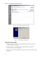
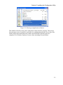
2. As shown in Figure 2-3, scroll down the list of applications and select the RTU
CONFIGURATION UTILITY by clicking on it.
3. Press the ADD/REMOVE button and follow the instructions that come up in the following
dialog boxes.
2-2
Section 2. Installing the Configuration Utility
Figure 2-3. Selecting an Application to Remove
This method will safely remove the Configuration Utility from the computer. This process
does not remove user-created files such as device configuration and logic files so some files
and the folders that contain them may still be on the hard disk when the removal is
completed. Use Windows Explorer to remove these remaining files and folders.
2-3
Section 2. Installing the Configuration Utility
2-4
3. SETTING UP COMMUNICATIONS
DIRECT RS-232 CONNECTION.......................................................................3-1
Ports and Cables.......................................................................................3-2
Configuration Utility Settings for Direct Connection..............................3-3
VIA RADIO.........................................................................................................3-4
Connections..............................................................................................3-4
Configuration Utility Settings for Radio Communications .....................3-4
VIA PHONE MODEM........................................................................................3-5
Connections..............................................................................................3-5
Configuration Utility Settings for Phone Modem Communications .......3-5
TESTING COMMUNICATIONS.......................................................................3-9
3. SETTING UP COMMUNICATIONS
There are several options available when it comes to communicating with the Controllers or
RTUs that are being set up with the Configuration Utility. Not only does the Core module in
a device have a serial port for communications (J2), the RTUs can also have Radio Interface
or Phone Modem modules installed, and can be configured via either of these paths as well.
Note:
Only the RTUs can be configured via their Radio Interface or Phone Modem
modules. Controllers cannot support Phone Modem modules. They can support
two-way communications with RTUs via their Radio Interface modules; however,
Controllers cannot receive programming information intended for them via the
radio. This means that Model 1730 Controllers can only be configured via direct
connection to their serial ports.
When the Configuration Utility needs to communicate with a Controller or RTU for tasks
besides configuration, the same communications channels are available and are listed in
Table 3-1.
Table 3-1. Available Communications Links
Task
Configure RTU
Configure Controller
Reset configuration
Retrieve or clear Logger data
from RTU
Upgrade RTU firmware
Upgrade Controller firmware
Available Comm. Links
RS-232
Phone
Radio
RS-232
RS-232
RS-232
Phone
Radio
RS-232
RS-232
This section presents the process of setting up the three ways of communicating with devices.
This section will make it easy to get your communications path set up and easy to
troubleshoot if the need arises. For information on using the Configuration Utility to perform
specific tasks, see Sections 4 through 8.
This section first discusses the RS-232 communications link, then the radio link, and lastly
the phone modem link. The section ends with a simple test to make sure that the
communications link is functioning.
DIRECT RS-232 CONNECTION
There are two issues to deal with when connecting directly to the device. One is the cabling
necessary to connect the computer to the serial port on the Core module, and the other is
selecting the serial communications parameters of the Configuration Utility.
3-1
Section 3. Setting Up Communications
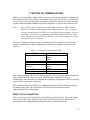
Ports and Cables
The Core module used in both Controllers and RTUs has two serial ports on it. One is labeled
J2 and is found next to the fuse socket on the long, front face of the module. This port uses a
9-pin, female, D-connector. The pin assignment for the necessary signals is the same as that
used by external modems. The pin out for a cable to connect to this port is shown in Table
3-2. Use this serial port to connect directly with a device.
Table 3-2. Serial Cable for Core Module Port J2
PC Com Port
(female)
Pin #
Pin #
RTU Port J2
(male)
—
1
1
—
RX Data
2
2
TX Data
TX Data
3
3
RX Data
DTR
4
4
DTE
Signal GND
5
5
Signal GND
DSR
6
6
DCE
RTS
7
7
CTS
CTS
8
8
RTS
—
9
9
—
—
jumper 4 to 6
jumper 7 to 8
—
The genders listed in the column headings refer to the connectors on the cable.
The second Core module serial port is available only on the RTU; it is labeled P3. This port
is located on the end of module opposite the expansion bus connector (just around the corner
from J2). It uses a male, 9-pin D-connector, and its pin assignments are the same as those
used on the Com port of a PC. This port is usually used to connect an RTU Phone Modem
module to its Core module. It is not normally used for direct connect with a device, but it
could be (only if the device is an RTU). Its cable pin assignment is shown in Table 3-3.
Note:
3-2
Core module P3 is only functional on RTUs. Core module P3 is not functional on
Controllers.
Section 3. Setting Up Communications
Table 3-3. Serial Cable for RTU Core Module Port P3
PC Com Port
(female)
Pin #
Pin #
RTU Port P3
(female)
—
1
1
—
RX Data
2
2
RX Data
TX Data
3
3
TX Data
DTR
4
4
DTE
Signal GND
5
5
Signal GND
DSR
6
6
DCE
RTS
7
7
RTS
CTS
8
8
CTS
—
9
9
—
—
jumper 4 to 6
jumper 7 to 8
—
The genders listed in the column headings refer to the connectors on the cable.
Configuration Utility Settings for Direct Connection
As far as the set up of the Configuration Utility goes, there is very little to do. The
Configuration Utility negotiates baud rate with the device when it initially attempts
communication with it. All the Configuration Utility needs to know is that the
communication is going to occur via a direct serial connection and which PC Com port to
use.
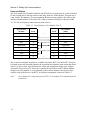
To start, click on the Device heading on the menu bar to open the Device menu. See Figure
3-1.
Figure 3-1. Device Communication Menu
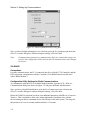
Choose the last item on the menu, COMMUNICATION, to open the PC ÅÆ Device
Communications dialog box shown in Figure 3-2. If not already selected, select DIRECT
SERIAL by clicking on its radio button. Then the available serial ports will be listed in the
drop down box in the SERIAL PORT area. Select the serial port you wish to use.
3-3
Section 3. Setting Up Communications
Figure 3-2. Device Communications Dialog Box
Once you have finished making these two selections, press the SAVE button to put them into
effect. To exit the dialog box without saving the settings, click on Cancel.
Note:
Communications parameters (communications link, port, and modem strings) are
saved by the Configuration Utility and used for all communications until changed
by the user.
VIA RADIO
Connections
For radio communications, the PC is connected directly to a Model 1730 Controller, and the
RTU in question communicates with the Controller via its Radio Interface module (also
called “Radio Modem”).
Configuration Utility Settings for Radio Communications
To communicate with an RTU via its Radio Modem module, open the PC Å Æ Device
Communications dialog box shown in Figure 3-2 and press the Radio Modem button.
Once you have selected Radio Modem, press the SAVE button to put your selection into
effect. To exit the dialog box without saving the settings, click on Cancel.
Below the COM Port selection box there is an additional parameter called RADIO COMMAND
TIMEOUT. This is included to allow some timing adjustment if problems arise with the
devices timing out before commands arrive due to delays in the radio system. The range for
this parameter is 10 to 60 seconds, and the default is 15 seconds.
3-4
Section 3. Setting Up Communications
Communications via radio are basically the same as a Direct Connect except that a check is
made before continuing with the communications. The Configuration Utility verifies that a
Controller is connected to the PC through their respective serial ports, and that the Controller
has a Radio Modem installed.
VIA PHONE MODEM
Connections
For phone communications, the RTU is reached through its Phone Modem module via the
phone modem in the PC running the Configuration Utility. The PC communicates with the
RTU by dialing the RTU phone number.
Configuration Utility Settings for Phone Modem Communications
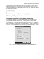
To communicate with an RTU via its Phone Modem module, open the PC Å Æ Device
Communications dialog box shown in Figure 3-3 and press the Phone Modem button.
As shown in Figure 3-3, when the Phone Modem option button is selected, the PC Modem
Setup command button becomes enabled. This button opens the PC Modem Setup dialog box
(see Figure 3-4) for editing modem-related commands and information about the PC modem.
Figure 3-3. Device Communications Dialog Box with Phone Modem Selected
3-5
Section 3. Setting Up Communications
Figure 3-4. PC Modem Setup Dialog Box
The fields in the dialog box allow the user to set up their PC modem so the Configuration
Utility can use it for communicating with an RTU. All the fields call for modem command
strings. When the dialog box is first opened each field contains its default values. These
defaults assume an AT command set modem. If the default string does not work for your
modem, please consult your modem's user manual and modify the strings as necessary to
perform the same functionality.
A description of the functions of the AT command strings in this dialog box follows.
INITIALIZATION STRING
Modem initialization string. This tells the modem how it should behave when in
operation. The commands in this string are to be AT command set commands.
[ATE0L1M1Q0V1X4 S7=60 (Default)]
Required:
AT: Attention String - Used to prefix modem command strings.
E0: Character Echo - This disables the character echo feature of the modem. The
modem must not echo the command strings that are sent to it by the program.
Q0: Result Codes - This enables the modem to return result codes. The program
requires responses from the modem for successful communication.
V1: Verbose Result Codes - This tells the modem to response with "verbose"
result codes (i.e.: OK, CONNECT 2400, etc.) as opposed to numeric codes.
X4: Result Code Detail Level - This tells the modem what subset of result codes to
return. Level 4 is the highest and it requires the modem to return the following
3-6
Section 3. Setting Up Communications
result codes as well as detecting dial tone: OK, CONNECT, RING, NO
CARRIER, ERROR, CONNECT ####, NO DIALTONE, and BUSY.
Note: If your modem does not have the capability to detect dial tone then try using
"X3".
S7=60 Carrier Detect Timeout - This is the maximum amount of time the modem
will allow to establish a connection with the target modem before
considering the attempt a failure. The time unit for this setting is in seconds.
Note: If you are experiencing longer times to establish a connection, then you may
consider increasing this value, though the default value should be adequate.
Optional:
L1: Low speaker volume - Sets the modem speaker to its lowest audible setting.
M1: Modem Speaker - Enables the modem speaker.
DIAL STRING
Specifies the method to use when dialing a phone number through the modem.
Usually used to select either Tone or Pulse dialing. [ATDTW (Default)]
Required:
AT: Attention String - Used to prefix modem command strings.
DT: Dialing Method - This tells the modem to use tone dialing as opposed to pulse
dialing.
Note: If your phone system does not support tone dialing then you may change this
setting to "DP" for pulse dialing.
Optional:
W: Wait for Dialtone - This forces the modem to detect dial tone before dialing the
phone number, thus minimizing the error of dialing too soon.
Note: If your modem does not have the capability to detect dial tone then try
removing this command from the end of the string.
HANGUP STRING
AT command used to return the modem on hook (hang up). [ATH (Default)]
Required:
AT: Attention String - Used to prefix modem command strings.
H: Hangup - Puts the phone line on hook.
ESCAPE STRING
AT command used to get the modem’s attention. [+++ (Default)]
Required:
+++: Escape String - used to get the modem's attention; breaks the modem out of
any current communication and waits for further commands.
3-7
Section 3. Setting Up Communications
RESET STRING
AT command to reset the modem to its factory-preset values. This is used only to
guarantee a common starting point before issuing the Initialization String. [AT&F
(Default)]
Required:
AT: Attention String - used to prefix modem command strings.
&F: Reset Factory Settings - Returns modem to the factory default settings.
“AT&F” was chosen over “ATZ” for the reason that it gives the modem a
known starting point, where “ATZ” only resets the modem to its current
settings.
SAVE PROFILE STRING
AT command to save a modem’s current configuration to a User Profile. This User
Profile is stored and recalled using the modem’s memory. This is used to save the
modem’s configuration before initializing it with the Configuration Utility’s
Initialization String so that it can be restored to its previous state with the Restore
Profile String. This is done so that the Configuration Utility will not affect the
modem’s configuration for use with the user’s other modem applications. The only
drawback is that it does overwrite one of the modem’s User Profile memory locations
in the process. [AT&W0 (Default)]
Required:
AT: Attention String - used to prefix modem command strings.
&W0: Save User Profile - Saves the modem's current settings in the modem's
memory for Profile0 (if supported). This is done so that the modem can be
restored to its original settings after the program is finished using it.
Note: If your modem does not support this feature or if you do not want the
Configuration Utility to use this feature, this entire command string field may
be left blank.
RESTORE PROFILE STRING
AT command to restore a User’s Profile from the modem’s memory. This command
is used to restore the modem’s previous configuration. [AT&Y0 (Default)]
Required:
AT: Attention String - used to prefix modem command strings.
&Y0: Restore User Profile - Restores the modem's current settings from the
modem's memory for Profile0 (if supported). This command is used after the
program is finished using the modem to restore the modem's previous settings.
Note: If your modem does not support this feature or if you do not want the
Configuration Utility to use this feature, this entire command string field may
be left blank.
Next to each of the modem string fields is a DEFAULT command button. Each default button
resets the string to its factory default value.
3-8
Section 3. Setting Up Communications
Underneath the modem strings is a DETECT MODEM button. When this button is clicked, the
PC attempts to communicate with a modem at the COM port selected in the PC Å Æ Device
Communications dialog box. Upon completion, a message box reports whether or not a
modem was found at that COM port.
After filling in the fields, click on the SAVE button to save your settings and close the dialog
box. To exit the dialog box without saving your settings, click on CANCEL.
When you close the PC Modem Setup dialog box, the PC Å Æ Device Communications
dialog box appears. To put your PC modem settings into effect, click on the SAVE button. To
exit the dialog box without saving the settings, click on CANCEL.
TESTING COMMUNICATIONS
The necessary connections now have been made and the appropriate dialog boxes have been
filled out. Now it is time to test the communications link with a device by simply reading
(downloading) its configuration and then checking that the configuration file is accurate.
Make sure the device is powered up and the Core module has had time to query the status of
its modules. You should know the device type (RTU or Controller), its address, and the
number and type of modules installed in the device.
The first thing to do is to click on the DEVICE selection from the menu bar and open the menu
shown in Figure 3-1. Choose the CONFIGURATION selection at the top of the menu. The
program provides three selections, prompting you to choose to read from a device, write to
one, or reset the configuration to the defaults. Click on READ. The program will bring up the
dialog box shown in Figure 3-5. Check the READ DEVICE CONFIGURATION box and then press
CONTINUE.
Figure 3-5. Read From Device Dialog Box
The Communications Check List shown in Figure 3-6 is then displayed. The text in bold
shifts depending on which communications link is currently being used.
3-9
Section 3. Setting Up Communications
Figure 3-6. Communications Check List Form
Press the CONTINUE button at the bottom of the form to move onto actually establishing a
link to the device. The program displays the Communications Status dialog box shown in
Figure 3-7.
Figure 3-7. Communication Status Dialog Box
If you are reading from a device via radio, the Configuration Utility prompts for a device
address so it knows which device to contact (see Figure 3-8).
3-10
Section 3. Setting Up Communications
Figure 3-8. Device Address Dialog Box
If you are reading from an RTU via phone, the Configuration Utility prompts for the RTU
phone number.
If the device has a password, the Configuration Utility prompts you for it with the dialog box
shown in Figure 3-9. Note that device passwords are case sensitive.
Figure 3-9. Device Password Dialog
When the configuration has been read, check that the type of device (RTU or Controller), its
address, and the number and type of modules in it are correct. If you cannot correctly read a
device’s configuration, do not try to use the Configuration Utility for configuring, retrieving
data, or upgrading firmware. You must first troubleshoot the communications links. If
problems persist, call Zetron for assistance.
For information about using the communications links for configuring devices,
retrieving/clearing logger data, and upgrading firmware, see Sections 5 through 8.
3-11
Section 3. Setting Up Communications
3-12
4. GETTING STARTED
GENERAL TOOLS .............................................................................................4-1
Menu Bar .................................................................................................4-1
Toolbars ...................................................................................................4-2
Status Bar .................................................................................................4-3
CHANGING YOUR BACKGROUND COLOR ................................................4-4
USING SHORTCUT KEYS................................................................................4-4
ONLINE HELP....................................................................................................4-5
4. GETTING STARTED
Before using the Configuration Utility to configure a device, retrieve logger data, or upgrade
firmware, read through this section about tools and screens that are generic to most parts of
the program. Knowing how to use the tools will help you use the Configuration Utility more
efficiently. You can also step through the Configuration Utility without communicating with
a device to get a feel for where things are.
To open the Configuration Utility, select Programs on your Start menu. Then select the RTU
Configuration Utility (it may be next to Zetron, depending on the file locations selected
during installation).
GENERAL TOOLS
The Configuration Utility runs under Windows and has many of the attributes of a Windows
program. A few other items have been added and adapted to the Windows environment.
Menu Bar
The menu bar is under the Configuration Utility’s title bar (as shown in Figure 4-1). The
menu bar uses a drop-down menu list to provide selections for performing the actions and
operations of the program. Most of these menu items are typical to Windows programs (e.g.,
Open, Save, and Close). To select a menu item, you can use a mouse to click on the item or
use a keyboard shortcut consisting of the ALT key and the underscored letter in the menu
item’s name.
Figure 4-1. Configuration Utility Menu and Toolbars
For a diagram of the menus and dialog boxes available, see the menu tree in Appendix A.
There are four selections on the menu bar: File, Device, Edit, and Help.
•
The File menu items have to do with setting configuration parameters and creating,
saving, and printing a configuration file.
•
The Device menu items have to do with interacting with a device. For example,
retrieving logger data is one of the selections under Device. Once communications
start, the Communications Status dialog box keeps you apprised of the data transfer
progress.
•
The Edit menu items help you use the Configuration Utility more efficiently.
4-1
Section 4. Getting Started
•
The Help menu items include the Help dialog box with tabs for Contents and Index.
The About … window, which has the version number of the Configuration Utility, is
also included here.
To exit from the Configuration Utility, select Exit from the File menu. If a device
configuration is currently open and has not been saved since changes were last made, the
program prompts you to save the device configuration before exiting.
Toolbars
As shown in Figure 4-1, the standard toolbar included with the program provides an alternate
method for accessing some of the common functions available from the menu bar. Though
these are very useful, they do not encompass the entire range of program functions. To allow
for more flexibility, you can add or remove toolbars, customize the standard toolbars, and/or
create your own.
To access the customizing feature, position the mouse over the menu bar or toolbar and click
the right mouse button. This gives immediate access to a list of available toolbars, as well as
a CUSTOMIZE selection. Like toolbars in many Windows programs, you can move a toolbar to
the sides or bottom of your screen or to the very top (above the menu bar). You can also let it
float.
If you select CUSTOMIZE, the Customize dialog box opens. The available toolbars are listed
under the Toolbars tab, and the available program functions (commands) are listed within the
Categories under the Commands tab (shown in Figure 4-2). Creating your own toolbar or
modifying the available ones is as easy as dragging these commands onto (or off of) any
toolbar as long as this dialog box is open.
Figure 4-2. Toolbar Customizing Dialog Box
4-2
Section 4. Getting Started
Status Bar
The status bar is located at the bottom of the main window and displays relevant (cursor or
context sensitive) information. Figure 4-3 shows the position of the Status bar at the bottom
of the screen. This status bar is divided into seven segments, each with their own designated
function. For the purposes of explaining their functions, the segments are numbered left-toright.
Figure 4-3. Configuration Utility Status Bar
Segment 1:
The main segment is used for conveying general status
information. It displays anything from information about the
program’s operational status, to displaying the acceptable range
for the currently active device property field.
Segment 2:
The next segment constantly displays the current method of
communication between the PC and the device.
Segment 3:
The next segment to the right constantly displays the current serial
communications port used for communicating between the PC and
device.
Segment 4:
The next segment to the right, when active, displays the current
serial baud rate used to communicate between the PC and device.
This segment is blank when the program is not actively
communicating with a device.
Segment 5:
The next segment to the right, when active, displays the current
serial format (8N1, etc.) used to communicate between the PC and
device. This segment is also blank when the program is not
actively communicating with a device.
Segment 6&7:
The final two segments, six and seven, constantly display the
current PC date and time.
4-3
Section 4. Getting Started
CHANGING YOUR BACKGROUND COLOR
In the File menu, select Options. In the Options dialog box, click on the color sample next to
“Background” and you can change the background color.
USING SHORTCUT KEYS
Use shortcut keys when it is more convenient or when a mouse is not available.
With the shortcut keys, if your mouse does not work, you can still use the Configuration
Utility. And with some practice the shortcut keys make setting parameters much faster.
The tooltips that appear above icons on your toolbar show shortcut keys.
For menu and dialog box selections, press ALT and the underscored letter in the selection
name.
To move from field to field in a dialog box, use the TAB key to advance forward. To return to
a previous field, use SHIFT+TAB.
To assign values, use CTRL, ALT, SHIFT and arrow keys.
To select a radio button, select the group of radio buttons with the tab key and then use the
arrow keys to select one radio button.
For time and calendar settings, use the arrow keys. The up arrow increases the value, and the
down arrow decreases the value.
For moving from module to module or from I/O point to I/O point, use the module and I/O
point sliders at the bottom of the dialog box. Use the CTRL key and the arrow keys for
modules, and use the ALT key and the arrow keys for I/O points. If you add the SHIFT key
4-4
Section 4. Getting Started
while you press the CTRL/ALT and arrow keys, you jump to the end of the list of modules or
I/O points.
To exit a dialog box, use the ESC key.
ONLINE HELP
To access the online help, click on Help in the menu bar. This selection opens up the full text
of the help file. When you are in a dialog box and want to get information about a specific
field, press F1 when the cursor is in the field. Helpful information about the current field is
also displayed in the status bar at the bottom of the screen. If you do not know the meaning
of a toolbar button, let your mouse hover over it, and a tooltips explanation will be displayed.
4-5
Section 4. Getting Started
4-6
5. CONFIGURING A DEVICE
STARTING THE CONFIGURATION FILE......................................................5-1
Starting by Reading the Device Configuration........................................5-1
Starting by Opening a Previously Saved File ..........................................5-3
Starting with a New File ..........................................................................5-4
MODIFYING THE FILE ....................................................................................5-4
Cut............................................................................................................5-5
Copy.........................................................................................................5-5
Paste .........................................................................................................5-5
I/O Properties ...........................................................................................5-5
Module Properties....................................................................................5-5
Add/Remove Modules .............................................................................5-6
DEVICE INFO.....................................................................................................5-6
ADD/REMOVE MODULES...............................................................................5-8
Technical Note:........................................................................................5-9
CORE PROPERTIES ..........................................................................................5-10
Exception Setup .......................................................................................5-14
Real Time Clock ......................................................................................5-16
Local Logic Setup ....................................................................................5-17
MODBUS Setup (Controller Only) .........................................................5-17
CORE INPUTS....................................................................................................5-19
Run Time .................................................................................................5-20
Counter.....................................................................................................5-21
CORE OUTPUTS................................................................................................5-22
DIGITAL I/O .......................................................................................................5-24
RELAY OUTPUTS .............................................................................................5-27
ANALOG INPUTS..............................................................................................5-29
Accumulator Setup...................................................................................5-34
ANALOG OUTPUTS..........................................................................................5-35
PHONE MODEM................................................................................................5-40
RADIO MODEM.................................................................................................5-42
FINISHING AND WRITING TO THE DEVICE...............................................5-44
Saving the Configuration File..................................................................5-44
Resetting the Configuration File..............................................................5-45
Printing the Configuration for a Final Check ..........................................5-45
Writing the Configuration File to the Device ..........................................5-45
Device Date and Time .................................................................5-46
Device Password..........................................................................5-47
5. CONFIGURING A DEVICE
This section covers the configuring of the various modules that make up a device. It
describes starting a configuration file, saving the file, and writing it to the device. Section 6
covers the setting up local logic for an RTU.
This section discusses the modules as individual units without regard to the device,
Controller or RTU. Because only one module is device-specific (the Phone Modem module
only functions in an RTU), most information in this section applies to both Controllers and
RTUs. The device type is only noted when settings are specific to a Controller or RTU.
Before beginning you should have handy a diagram or list of your SCADA system, so you
know which modules belong to which devices, the names you want to assign to the devices
and I/O points, and the device and module addresses you want to use. Also think about
filenames you want to give the configuration files you will create.
STARTING THE CONFIGURATION FILE
You can start the configuration task in several ways:
•
You can read (download) the configuration from a device.
•
You can open a previously saved configuration file.
•
You can select New from the File menu to generate a default configuration file.
Starting by Reading the Device Configuration
The recommended way to start a configuration file is to read it from the device. This method
involves reading the configuration from the device, making additional settings, and then
writing the modified configuration file back to the device. When a configuration is read from
a device, the Configuration Utility gets data about the device, such as the type of device, the
number and type of modules, and the device and module addresses. Starting with that
information already in the file increases the likelihood that the configuration file will be error
free.
First select Configuration in the drop-down list under Device in the menu bar. It contains
functions for accessing a device’s configuration. Placing the cursor on the word
“Configuration” in the drop-down list opens three submenu items to the right: READ and
WRITE and RESET.
Select READ to read the device configuration. This selection opens the dialog box shown in
Figure 5-1. There is a checkbox for reading the current device configuration, and one for
reading the RTU Local Logic executable program. (You cannot modify this program once it
is read from the device. Checking this box only reads the executable file from the device and
saves it to a file, which you can use as a backup. See Section 6 for details.)
5-1
Section 5. Configuring a Device
Figure 5-1. Read From Device Dialog Box
After selecting Read Device Configuration, click on CONTINUE.
The program will bring up the checklist shown in Figure 5-2. The text in bold will shift
depending on which method of communication is being used.
Figure 5-2. Communications Check List
Press the CONTINUE button at the bottom of the checklist to move onto actually establishing a
link to the device.
If the device has a password programmed, the program will prompt you for it with the dialog
box shown in Figure 5-3. Note that device passwords are case sensitive.
5-2
Section 5. Configuring a Device
Figure 5-3. Device Password Dialog
After reading the configuration from the device, you will make additional settings and
modify the configuration as needed and then save the file.
You can select Close or Save in the drop-down list under File in the menu bar. If you select
Close, the currently open device configuration is closed. If the currently open configuration
has been changed, then you are prompted to save it before closing.
If you select Save, the currently open device configuration is saved. If the currently open
device configuration has not yet been saved, the program opens a Save As dialog box to
prompt you for a file name.
After saving the configuration file, write it back to the device. It is a good idea to document
the device’s setting by printing the configuration. The tasks of modifying the file, printing,
and writing files to devices are described starting on page 5-4.
Starting by Opening a Previously Saved File
To open a previously saved configuration file, select Open in the drop-down list under File in
the menu bar. This opens a File Open dialog box to retrieve an existing device configuration
for editing. If a configuration is currently open, it is closed before opening another one. If the
currently open file has been modified and not saved, the user is prompted to save it before
opening the other configuration.
After opening the configuration file, make additional settings and modify the configuration
as needed. After modifying the file, use Save As to save the file as a new file, or use Save if
you want to overwrite the file you opened.
If you select Save As, the Save As dialog box asks you to specify a filename for the currently
open device configuration.
5-3
Section 5. Configuring a Device
After saving the configuration file, write it to the device. It is a good idea to document the
device’s setting by printing the configuration. The tasks of modifying the file, printing, and
writing files to devices are described starting on page 5-4.
Starting with a New File
To generate a default configuration file, select New in the drop-down list under File in the
menu bar. This generates and opens a new default device configuration file for editing. If a
configuration is currently open, it is closed before opening a new one. If the currently open
file has been modified and not saved, you are prompted to save it before creating the new
configuration.
After opening a new configuration file, you will make additional settings and modify the
configuration as needed and then save the file.
You can select Close or Save or Save As in the drop-down list under File in the menu bar. If
you select Close, the currently open device configuration is closed. If the currently open
configuration has been changed, then you are prompted to save it before closing.
If you select Save, the currently open device configuration is saved. If the currently open
device configuration has not yet been saved, the program opens a Save As dialog box to
prompt you for a file name.
If you select Save As, the Save As dialog box asks you to specify a filename for the new
device configuration.
After saving the configuration file, write it to the device. It is a good idea to document the
device’s setting by printing the configuration. The tasks of modifying the file, printing, and
writing files to devices are described starting on page 5-4.
MODIFYING THE FILE
Before starting to modify a configuration file, review the selections in the Edit drop-down
list. These commands can help you work with configuration files efficiently.
These commands are only active if a module dialog box in a configuration file is currently
loaded. They are used to copy information from one module dialog box to another.
5-4
Section 5. Configuring a Device
Cut
This selection copies whatever is selected to the Windows clipboard and removes it from its
current location.
Copy
This selection copies whatever is selected to the Windows clipboard and leaves it in its
current location.
Paste
This selection pastes the contents of the Windows clipboard into current cursor location.
I/O Properties
This selection is only available when input or output module dialog boxes are active. It is
disabled (grayed) otherwise. It opens two submenu items to the right: Copy To … and Reset.
If you select Copy To, it copies all properties (except for the Name property) for currently
selected I/O point to another I/O point of the same type. This command opens the dialog box
in Figure 5-4 for you to select the destination I/O.
Figure 5-4. Copy Input/Output To Dialog Box
If you select reset, all properties (except for the Name property) for currently selected I/O
point or module are returned to their default values.
Module Properties
This selection is only available when input or output module dialog boxes are active. It is
disabled (grayed out) otherwise. It opens two submenu items to the right: Copy To … and
Reset.
If you select Copy To, it copies all properties (except for the Name property) for currently
selected I/O module to another I/O module of same type. This command opens the dialog
box in Figure 5-5 for you to select the destination I/O module.
5-5
Section 5. Configuring a Device
Figure 5-5. Copy Module To Dialog Box
If you select reset, all properties (except for the Name property) for currently selected I/O
point or module are returned to their default values.
Add/Remove Modules
This selection opens the Add/Remove Modules dialog box. This selection is only available
when a module property dialog box is open. The Device Info dialog box also allows you to
access this dialog box (see “ADD/REMOVE MODULES” on page 5-8).
DEVICE INFO
Upon loading or opening a device configuration file for editing, the Device Info dialog box is
the first dialog box displayed (see Figure 5-6). This is the starting point for configuring a
device. This dialog box gives basic information about the device and allows you to build a
device with the Add/Remove Modules button. It is the gateway to configuring the Core
module properties, the I/O points, and the communications modules. This dialog box displays
general information about the device at the top. You cannot modify the information from this
dialog box.
5-6
Section 5. Configuring a Device
Figure 5-6. Device Info Dialog Box
The top half of the dialog box displays:
DEVICE NAME
User-given name for the device (programmable in the Core Properties dialog box).
DEVICE TYPE
Displays either the Model 1730 Controller or the Model 1732 RTU (selectable on
Core Properties dialog box).
DEVICE ADDRESS
Displays the current device address (programmable on Core Properties dialog box).
DEVICE SOFTWARE & VERSION
Device’s current software number and version. This information is read from the
device by the Configuration Utility.
SOFTWARE OPTIONS
A list box to display the current software options installed on the device. This
information is read from the device by the Configuration Utility.
The middle section of this dialog box displays the total number of each type of module
installed in the device.
There is also a command button, which opens its own dialog box, for adding and removing
modules in a device’s configuration.
5-7
Section 5. Configuring a Device
Located at the very bottom of the dialog box are two rows of command buttons that display
dialog boxes for editing device properties. Each of these opens a window specific to the task.
The button for Keypad/Display is not enabled because that function is not available.
ADD/REMOVE MODULES
Figure 5-7. Add/Remove Modules Dialog Box
Use the Add/Remove Modules window to change the number and type of modules. This
window is accessible through a few different methods. One method is from the command
button on the Device Info dialog box. Another method is using the main menu bar selection
under EDIT | ADD/REMOVE MODULES. Yet another method is to click the right mouse button
while the mouse cursor is over one of the module windows.
On the left side of the dialog box are command buttons, one for adding each type of module.
If the device configuration has reached its module limit, or the module is no longer available
as an option to the user, the command button is disabled (grayed out).
When one of these command buttons is clicked, a module of that type is added to the
device’s configuration using the address in the Module Address box. If the new module’s
address conflicts with an existing address for that module type, the user is alerted of this fact
and is returned to the dialog box to try again. If successful, the new module is added and
displayed in the list box on the right side of the dialog box.
The INSTALLED MODULE list box lists all currently installed modules and their addresses. The
list is sorted first by module type, then sequentially by address. You may select only one
module from the list at a time. When a module is selected, the Module Address box
automatically displays its address. The Remove and Change Address command buttons are
also enabled upon making a selection and are applied to the currently selected module.
5-8
Section 5. Configuring a Device
To change a module address, select a module first, modify the address, and then click on the
Change Address button.
Technical Note:
Please note the following recommended steps when adding, removing, or otherwise changing
a device’s installed module configuration. Failure to adhere to these guidelines may result in
an undesirable device configuration.
•
Before physically changing any device modules, read the entire device configuration
(including any Local Logic) and save it to a file. This guarantees you have a
configuration file of the device before any modifications were made.
•
IMPORTANT: Remove power from the device prior to swapping modules. The
modules are not designed to be hot-swappable and any module changes are not
recognized until power is cycled to the device.
•
With power removed from the device you may safely swap out any of the device’s
modules.
•
After all module changes have been made and connections verified, reapply power to
the device. This causes the device to perform its detection routine to determine which
modules are physically attached.
•
Open your previously saved configuration file and modify the module configuration to
correspond to the physical changes.
•
Save the modified configuration file to a new file name so the original configuration
file is not overwritten.
•
Write the new configuration file to the device.
•
Once you have verified that the new configuration is working properly, you may
delete the old configuration file if you believe you will have no further use for it.
Note:
If the physical configuration of a device does not match its programmed
configuration errors and/or undesirable operation may occur. For example, if a
device is programmed to expect a communication module (e.g. a Radio Modem or
Phone Modem) and one is not physically installed, the device will go into an error
mode. If an I/O module is expected but not found, all dependencies (e.g. Local
Logic) upon the associated I/O points may not behave as expected.
5-9
Section 5. Configuring a Device
CORE PROPERTIES
Figure 5-8. Core Properties Dialog Box
The Core Properties dialog box holds all of the inherent properties of the core module
(except for its I/O properties), whether it is a Controller or RTU. The dialog box is basically
broken down into six sections:
1. The main section of the dialog box with the device’s name, type, address, and
phone number (if applicable).
2. A section holding various properties.
3. Device Serial Ports properties.
4. Base Station (RTU only) properties.
5. Protocol (Controller only) properties.
6. The control area with the black background at the bottom of the dialog box.
Because of the amount of information this dialog box has to hold some of the lesser used, or
easily detached, properties are accessible through their own dialog boxes. These dialog boxes
are accessed by clicking on the appropriately labeled command button. These dialog boxes
are: Exception Setup, Real Time Clock, Local Logic, and MODBUS Setup.
5-10
Section 5. Configuring a Device
The main section of the dialog box is located at the top allowing the user to modify the
following properties:
DEVICE NAME
Enter a name for the device. It is recommended that you use a location name or some
logical naming scheme. You could also use this name for the configuration file name.
The string can be from 0 to 16 characters in length. The default condition is for this
field to be blank.
DEVICE TYPE
Enter the type of device you want to configure. The choices are: Model 1730
Controller or Model 1732 RTU. Check the label near J2 on the Core module to ensure
you are configuring the correct type of device. Figure 5-9 shows a label for an RTU.
RTU
1732
601-0886
(c) ZETRON, INC
Figure 5-9. Example of Label that Indicates Type of Device
DEVICE ADDRESS
Enter the Device’s address. Next to the Device Address field is a graphic simulating
an 8-bit DIP switch. The program automatically calculates the required DIP switch
setting to match the number entered. This gives you a visual representation of how
the device’s Core module DIP switch should be set (the numbers on the graphic
correspond to the black number on the switch itself, not to the numbers on the module
label). The range for this parameter is 0 to 65,535. The default setting is 0 for
Controllers and 1 for RTUs.
When using the MODBUS protocol, the valid address range is 1 to 247. The address
247 is reserved for use by the keypad/display module when serial communications is
used between the controlling PC and the RTU.
DEVICE PHONE NUMBER
A phone modem must be enabled on the RTU (Controllers do not support phone
modems) for this field to be enabled. Enter the phone number required to reach the
RTU via phone modem. This number is only stored in the device configuration file; it
is not stored in the device itself. This field is linked to the same database entry as the
DEVICE PHONE NUMBER field on the PHONE MODEM dialog box.
Below that is the group of miscellaneous properties which consists of:
POWER-UP MESSAGE ENABLE
Check/uncheck to enable/disable power-up messages. This selection controls whether
or not the device sends messages (e.g. product name, version number, etc.) to the
device’s Port1 serial port on power-up.
5-11
Section 5. Configuring a Device
EXCEPTION ENABLE
Check/uncheck to enable/disable exception reports. When enabled, it also enables the
Exception Setup command button.
EXCEPTION SETUP COMMAND BUTTON
When enabled, this command button opens the Exception Setup dialog box. This
command button is disabled (grayed out) when the Exception Enable checkbox is
unchecked.
DATA LOGGING OVERFLOW STRATEGY
Select how to handle a buffer overflow when the Data Logger is enabled. The choices
are DISCARD NEW RECORDS or OVERWRITE OLD RECORDS. The default setting is to
OVERWRITE OLD RECORDS. This field is disabled (grayed out) when the device type is
a Controller.
REAL TIME CLOCK COMMAND BUTTON
This command button opens the Real Time Clock dialog box. This dialog box is used
to enter the Device Time Zone property.
In the lower left corner of the dialog box is the Device Serial Ports section. It contains all the
properties for the device’s serial ports.
BAUD RATE
Select the baud rate for the currently selected serial port. The baud rates supported
are:
300 bps
1200 bps
2400 bps
The default baud rates are:
4800 bps
9600 bps
19200 bps
Port 0 (Core module J2)
Port 1 (Core module P3)
= 4800 bps
= 2400 bps
FORMAT
Select the serial data format for the currently selected serial port. The available
formats are:
8N1
8N2
8E1
8O1
(8 data, No parity, 1 stop)
(8 data, No parity, 2 stop)
(8 data, Even parity, 1 stop)
(8 data, Odd parity, 1 stop)
The default setting is 8N1.
On the right-hand side of the dialog box are the Base Station properties. These properties are
only available for an RTU type device; otherwise they are disabled (grayed out). RTUs
5-12
Section 5. Configuring a Device
respond to messages with their device address, to messages with their All Call address, and
to messages with their Group Call address.
CONTROLLER ADDRESS
Enter the address of the Controller to which the RTU device reports. The range for
this parameter is 0 to 65,535. The default for this parameter is 1.
ALL CALL ADDRESS
Enter the All Call Address. The All Call is a common address to which all RTU
devices that share it respond (in addition to their own address). The range for this
parameter is 0 to 65,535 (must be non-zero to enable). The default for this parameter
is 0 (disabled).
GROUP CALL ADDRESS
Enter the Group Call Address. The Group Call is a common address to which all RTU
devices that share it respond (in addition to their own address). The range for this
parameter is 0 to 65,535 (must be non-zero to enable). The default for this parameter
is 0 (disabled).
ULTRAC PHONE NUMBER
(This parameter supports ULTRAc.W. That program is no longer supported by
Zetron.) This field does not apply to RTUs in a MODBUS system. The range for this
parameter is 0 to 40 phone/modem dialing characters (0-9, *, #, -, “,”, punctuation,
pauses, second dial tone, etc.).
LOCAL LOGIC COMMAND BUTTON
When enabled (only supported for RTU type devices), this command button opens
the Local Logic Setup dialog box. It is the starting point for setting up RTU local
logic programs (see Section 6).
Below the Base Station properties is the Protocol section for selecting the communication
protocol for the Controller and specifying the RS232 Watchdog Mode and Timeout value.
These properties are only available for a Controller type device; otherwise they are disabled
(grayed out). The protocol selection is determined by which PC program the customer is
using for their central control software.
PROTOCOL
Select either ULTRAc or MODBUS as the central control software protocol for your
system. When MODBUS is selected, the MODBUS command button is enabled. The
default setting is for ULTRAc.
MODBUS SETUP COMMAND BUTTON
When enabled, this command button opens the MODBUS Setup dialog box.
5-13
Section 5. Configuring a Device
RS232 WATCHDOG MODE
Select the action the controller initiates if communications with the PC via the RS232 port fail for the period specified in the RS232 Watchdog Timeout. The choices
are:
Do Nothing
Turn On Core Output #4
Turn On Core Module Relay
The default setting is to Do Nothing.
RS232 WATCHDOG TIMEOUT
Specify the timeout period for the RS232 Watchdog feature. If no message is received
from the PC within this period, the controller will initiate the action specified in
RS232 Watchdog Mode. The range for this parameter is 0 to 86,400 seconds (24
hours max.). The default is 60 seconds.
Exception Setup
Figure 5-10. Exception Setup Dialog Box
The Exception Setup dialog box holds all properties pertaining to Exception Report handling.
EXCEPTION REPORT CHANNEL
Select which communications method is used by a device for exception reports to a
Controller or to ULTRAc.W. This field is disabled (grayed out) and automatically
selected to DIRECT SERIAL when the device type is a Controller. The available choices
are: Radio, Phone, and Direct Serial. If the RTU is in a MODBUS system, Phone is
available only for units running version 2.0 or later firmware (and this is only true
when the system control software is “Lookout”, by National Instruments).
5-14
Section 5. Configuring a Device
The default settings are:
Radio (for an RTU)
Direct Serial (for a Controller)
INITIAL RETRY INTERVAL
Enter the Initial Retry Interval. This is the period of time that the device will wait
before trying to communicate through the Exception Report Channel after the first
failure. The range for this parameter is 2 to 3600 seconds (1-second resolution). The
default value is 5 seconds. Please note that the default value was chosen with radio
linked RTUs in mind, and should be increased if the RTU reports by phone.
MAX RETRY INTERVAL
Enter Max Retry Interval. The retry interval increments by a random amount on each
retry, but it is never allowed to exceed this setting. The range for this parameter is 2
to 3600 seconds (1-second resolution). The default value for this parameter is 300
seconds.
MAX RETRY INCREMENT
Enter Max Retry Increment. The retry interval is incremented by a random amount
between zero and the value of this setting on each retry without a response. The range
for this parameter is 0 to 200 seconds (1-second resolution). The default value for this
parameter is 15 seconds. Please note that, setting this value to zero causes the retries
to occur at a fixed interval, which is the Initial Retry Interval.
MAX RETRY ATTEMPTS
Enter the maximum number of retries the device can attempt to send an exception
report without a communications failure occurring. A communications failure occurs
when an exception report has been sent “Max Retry Attempts + 1” without being
acknowledged. For example, if you want a communications failure to occur after 5
unacknowledged exception reports, set the Max Retry Attempts to 4 (the initial report
+ 4 retries). The range for this parameter is 0 to 15 attempts. The default value for this
parameter is 2.
COMMUNICATIONS FAILURE MODE
Select how the controller should handle an exception reporting communications
failure. This property applies only to Controllers; an RTU uses Local Logic for
handling exception report communications failures.
To have the Controller turn off all its outputs, select TURN OUTPUTS OFF. To have the
Controller turn on its Core module relay, select TURN ON CORE MODULE RELAY. For
the Controller to do nothing in response, select DO NOTHING. The default setting is
DO NOTHING.
EXCEPTION PROTOCOL
This parameter tells the RTU whether to use the ULTRAc.W protocol or the
MODBUS protocol for reporting exceptions. This feature is only available when the
communications path between the controlling PC and the RTU is either a direct serial
5-15
Section 5. Configuring a Device
connection or a phone modem. If the radio is selected for the exception reporting
channel, then this option is not available. Setting this parameter to MODBUS allows
the RTU to send an unsolicited message to the control program (such as the Lookout
program by National Instruments), so that the program may send a message back to
the RTU requesting the status of each input/output in the device.
The available choices are ULTRAc or MODBUS. The default setting is ULTRAc for
RTUs. This option is not available for the Controller since the MODBUS software in
the PC can be set to simply poll the Controller more often.
Real Time Clock
Figure 5-11. Real Time Clock Dialog Box
The Real Time Clock dialog box contains necessary information used to set the Real Time
Clock of the device.
DEVICE TIME ZONE
Enter the difference in time zones (in hours and minutes) between the device
locations (sites) and the location of the PC running the SCADA control software. The
range for this parameter is:
-23:59
[HH:MM Behind
to
to
+23:59
HH:MM Ahead]
The default entry is +00:00 [HH:MM Ahead]. Please note that this parameter applies
only to RTUs, as Controllers must be co-located with their PCs.
AHEAD
Device Time Zone direction relative to local (PC) time. This option button should be
selected if the device time zone is “Ahead” of the local (PC) time zone. This option
button cannot be selected simultaneously with the “Behind” option button.
BEHIND
Device Time Zone direction relative to local (PC) time. This option button should be
selected if the device time zone is “Behind” the local (PC) time zone.
These properties are used during a configuration transfer to set the Real Time Clock of the
destination device. Time adjustment is calculated according to these properties by the
Configuration Utility before sending the command to set the device’s Real Time Clock.
5-16
Section 5. Configuring a Device
Local Logic Setup
This topic is covered in Section 6.
MODBUS Setup (Controller Only)
Figure 5-12. MODBUS Setup Dialog Box
The MODBUS Setup dialog box contains properties directly related to MODBUS protocol
operating parameters. These properties apply only to a Controller type device. This dialog
box is inaccessible if the device is an RTU, or a Controller using the ULTRAc protocol. A
MODBUS Controller can support up to 150 RTUs.
RTU INFO:
Combination box with a list of all RTUs that report to this Controller.
RTU INFO: ADDRESS
Enter the address of the RTU. The range is 1 to 247, and it defaults to 1. A Model
1730 with the MODBUS option and version 2.0 or later firmware can support up to
150 RTUs (prior to version 2.0 the limit was 50).
RTU INFO: TYPE
Select a type of RTU for each new address entered in the previous field. When a new
RTU Address is entered, an RTU Type must be selected. The selections available for
this parameter are: M1708, M1716, or M1732. The default setting is M1732.
RTU INFO: ENABLED
Check/uncheck to enable/disable the selected RTU for polling. The default setting for
this parameter is DISABLED. Please note that the RTU can be disabled without losing
the other RTU specific settings. Disabling an RTU removes it from the auto polling
sequence.
5-17
Section 5. Configuring a Device
ADD RTU COMMAND BUTTON
Adds an RTU to the list using the Address, Type, and Enabled values.
CHANGE RTU COMMAND BUTTON
Modifies an RTU in the list using the Address, Type, and Enabled values.
REMOVE RTU COMMAND BUTTON
Removes the currently selected RTU from the list.
AUTOPOLLING: POLL CYCLE INTERVAL
Enter the Poll Cycle Interval. This is the time between successive polling cycles,
defined as the time between the end of one autopoll cycle and the start of the next.
The range for this parameter is 0 to 86,400 seconds (24 hours max.). The default
value for this parameter is 300 seconds (5 minutes).
AUTOPOLLING: RTU POLL INTERVAL
Enter the RTU Poll Interval. This represents the interval between receiving a response
from the last RTU polled, and sending a poll to the next RTU in the sequence. The
range for this parameter is 0 to 3,600 seconds (1 hour max.). The default value for
this parameter is 0 seconds.
AUTOPOLLING: RETRIES
Enter the number of retries, when autopolling, for an RTU that fails to respond. The
range for this parameter is 0 to 10, and the default setting is 2.
AUTOPOLLING: RETRY TIMEOUT
Enter the autopolling timeout period. The Timeout period begins at the end of the
polling transmission from the Controller and determines when an RTU is considered
to have failed to respond. The range for this parameter is 2 to 300 seconds (5 minutes
max.). The default setting for this parameter is 5 seconds.
AUTOPOLLING: ENABLED
Check/uncheck to enable/disable autopolling. The default setting is Disabled.
LOCAL RTU STATUS
Check/uncheck to enable/disable storage of RTU I/O status within the Controller’s
memory between polls. The default condition for this parameter is enabled.
5-18
Section 5. Configuring a Device
CORE INPUTS
Figure 5-13. Core Inputs Dialog Box
The Core Inputs dialog box contains all properties related to the digital inputs on the device’s
Core module. The dialog box is arranged into five areas or sections:
1.
2.
3.
4.
5.
The main area of the dialog box with the Core Input’s name, mode, etc.
Run Time section
Counter section
Core Input information frame
The dialog box’s control area.
The main section of the dialog box is located at the top allowing the user to modify the
following properties:
NAME
Enter a name for the input. The range for this parameter is a string of 0 to 15 ASCII
characters. The default string supplied by the program is “Core Din x” where x is the
input number 1-8.
MODE
Select the mode that corresponds to the normal (inactive) state of the signal attached
to the input. Use NORMALLY OPEN INPUT for a signal that is an open circuit or a high
voltage when not active. Use NORMALLY CLOSED INPUT for a signal that is a closed
5-19
Section 5. Configuring a Device
circuit (to ground) or a low voltage when not active. The default setting is NORMALLY
OPEN INPUT.
ACTIVATION DELAY
Enter the time (measured in seconds) that the input must remain in the specified state
to be considered as an alarm. The range for this parameter is 0 to 3600 seconds. The
default setting is 1 second.
DEACTIVATION DELAY
Enter the time (in seconds) that the input must remain in the specified state to not be
considered as an alarm. The range for this parameter is 0 to 3600 seconds. The default
setting is 1 second.
EXCEPTION ENABLE
Check/uncheck to enable/disable exception reporting. The default for this parameter
is enabled.
LOGGING ENABLE
Check/uncheck to enable/disable data logging. The default for this parameter is
disabled. This setting applies only to RTU type devices.
Run Time
In the lower left-hand corner of the Core Inputs dialog box is the Run Time section,
contained within its own frame.
RUN TIME: THRESHOLD
The threshold value is used for both exception reporting and data logging. When the
run time value crosses the threshold, an exception is reported (if enabled) and/or the
run-time value is logged (if enabled). The range for this parameter is 1 to 31,622,400
seconds (1 leap year max.). The default setting is 1 second.
RUN TIME: EXCEPTION ENABLE
Check/uncheck to enable/disable Run Time exception reporting. The default for this
parameter is disabled.
RUN TIME: LOGGING ENABLE
Check/uncheck to enable/disable Run Time data logging. The default for this
parameter is disabled. This setting only applies to RTU type devices. The field is
disabled (grayed out) when the device type is a Controller.
5-20
Section 5. Configuring a Device
Counter
The Counter section is located in the lower right-hand corner of the dialog box containing all
of the counter-related properties. The scaled counter value (the output sent to the control
software) is arrived at using the following equation:
(Accumulated value X Multiplier) + Offset = Scaled Counter Value
COUNTER: MULTIPLIER
Enter the Counter Multiplier. This factor is used in converting the counter totals into
the units desired by the user. This factor is applied to the counter total before the
offset is added. The allowable range for this parameter is from -1020 to +1020. The
default setting is 1.0.
COUNTER: OFFSET
Enter the Counter Offset. This offset is used in converting the counter totals into the
units desired by the user. After the accumulated value has been multiplied by the
Counter Multiplier, the offset is added to finish the scaling process. The allowable
range for this parameter is from -1020 to +1020. The default setting is 0.0.
COUNTER: UNITS
Enter the user-defined Counter Units. The range for this string is 0 to 5 ASCII
characters. The default is for this string to be blank.
COUNTER: THRESHOLD
The threshold value is used for both exception reporting and data logging. When the
counter value crosses the threshold, an exception is reported (if enabled) and/or the
counter value is logged (if enabled). The allowable range for this parameter is from 1020 to +1020. The default setting is 1.0.
COUNTER: HIGH SPEED
This checkbox selects whether or not the input can be used as a high speed counter or
not. When HIGH SPEED is checked, the count value is updated from the high-speed
counters available on the core module’s processor IC. When HIGH SPEED is not
checked, the count value is updated from the “debounced” input line itself. This is
considered the “low speed” mode.
Note: The High Speed feature only applies to inputs 1 through 5 of the Core module.
Inputs 6 through 8 are always in the low speed mode. This feature is not
available in the Digital I/O module’s inputs.
COUNTER: EXCEPTION ENABLE
Check/uncheck to enable/disable Counter Exception Reporting. The default for this
parameter is disabled.
5-21
Section 5. Configuring a Device
COUNTER: LOGGING ENABLE
Check/uncheck to enable/disable Counter Data Logging. This field is disabled
(grayed out) when the device type is a Controller.
The Core Input information box is located in the top right corner of the dialog box. It is for
informational purposes only (not modifiable by user). Located across the bottom is the dialog
box’s control area. The control area of the Core Inputs dialog box consists of a Core Inputs
Data Control, and the Save and Cancel command buttons.
CORE INPUTS DATA CONTROL
Selects another input. All fields on the dialog box are bound to the data and are
automatically updated to reflect the property values of the currently selected input.
CORE OUTPUTS
Figure 5-14. Core Outputs Dialog Box
The Core Outputs dialog box contains all properties related to the digital and relay outputs on
the device’s Core module. This dialog box has only three areas or sections:
1. The main area of the dialog box with the Core Output’s name, mode, etc.
2. Core Output information box
3. The dialog box’s control area.
5-22
Section 5. Configuring a Device
The main section of the dialog box is located at the top allowing the user to modify the
following properties:
NAME
Enter a name for the output. The range for this string is 0 to 15 ASCII characters. The
default entry for this string is “Core Dout x” where x is the output number 1-5 (5 is
the relay output).
MODE
Select the output mode for the output. When an output set to MOMENTARY OUTPUT is
turned on, it will stay on for the deactivation delay time, and then turn off
automatically. When an output set to LATCHED OUTPUT is turned on, it will stay on
until explicitly turned off. The default selection is LATCHED OUTPUT.
DEACTIVATION DELAY
Enter the Deactivation Delay to use for momentary outputs. When a momentary
output is turned on, it will stay on for the deactivation delay time, and then turn off
automatically. The range for this parameter is 1 to 3600 seconds. The default setting
is 1 second.
EXCEPTION ENABLE
Check/uncheck to enable/disable exception reporting. The default setting for this
parameter is enabled.
LOGGING ENABLE
Check/uncheck to enable/disable data logging. The default setting for this parameter
is disabled.
The Core Output information box is located in the top right corner of the dialog box. It is for
informational purposes only (not modifiable by user).
Located across the bottom is the dialog box’s control area. The control area of the Core
Outputs dialog box consists of a Core Outputs data control, and the Save and Cancel
command buttons.
CORE OUTPUTS DATA CONTROL
Selects another output. All fields on the dialog box are bound to the data and are
automatically updated to reflect the property values of the currently selected output.
5-23
Section 5. Configuring a Device
DIGITAL I/O
Figure 5-15. Digital I/O Dialog Box
The Digital I/O dialog box contains all properties related to digital inputs and outputs on
Digital I/O modules. The dialog box is divided into three main areas or sections:
1. The main area of the dialog box with the Digital I/O name, mode, etc.
2. The Digital I/O information box
3. The dialog box’s control area.
The main area of the dialog box allows the user to enter values for the following Digital I/O
properties.
NAME
Enter the name of the Digital I/O. The range for this string is 0 to 15 characters. The
default entry for this string is “Dio x:y” where x is the module address (0-15), and y is
the I/O number (1-16).
MODE
Select the appropriate input or output mode. The available choices are: NORMALLY
OPEN INPUT, NORMALLY CLOSED INPUT, LATCHED OUTPUT, and MOMENTARY
OUTPUT.
For inputs, select the mode that corresponds to the normal (inactive) state of the
signal attached to the input. Use NORMALLY OPEN INPUT for a signal that is an open
5-24
Section 5. Configuring a Device
circuit or a high voltage when not active. Use NORMALLY CLOSED INPUT for a signal
that is a closed circuit (to ground) or a low voltage when not active.
For an output, select an output mode. When an output set to MOMENTARY OUTPUT is
turned on, it will stay on for the deactivation delay time, and then turn off
automatically. When an output set to LATCHED OUTPUT is turned on, it will stay on
until explicitly turned off.
The default selection is NORMALLY OPEN INPUT.
ACTIVATION DELAY
This setting is for inputs only. Enter the time (measured in seconds) that the input
must remain in the specified state to be considered as an alarm. The range for this
parameter is 0 to 3600 seconds. The default setting is 1 second.
DEACTIVATION DELAY
This setting is used as a deactivation delay time for inputs and a momentary time for
outputs. The range for this parameter is 0 to 3600 seconds. The default setting is 1
second. For inputs, enter the time (in seconds) that the input must remain in the
specified state to not be considered as an alarm. When a momentary output is turned
on, it will stay on for the deactivation delay time, and then turn off automatically.
EXCEPTION ENABLE
Check/uncheck to enable/disable exception reporting. The default setting for this
parameter is enabled.
LOGGING ENABLE
Check/uncheck to enable/disable data logging. The default setting for this parameter
is disabled. This field itself is disabled (grayed out) when the device type is a
Controller.
The Digital I/O information box is located in the top right corner of the dialog box. It is for
informational purposes only (not modifiable by user). Located across the bottom is the dialog
box’s control area. The control area of the Digital I/O dialog box consists of a Module data
control, a Digital I/O data control, and the Save and Cancel command buttons. On the lower
right corner of the dialog box is a checkbox allowing the user to enable or disable an entire
module while retaining all of its properties.
MODULE DATA CONTROL
Selects another module. All fields on the dialog box are bound to the data and are
automatically updated to reflect the property values of the currently selected Digital
I/O of the currently selected module.
5-25
Section 5. Configuring a Device
DIGITAL I/O DATA CONTROL
Selects another Digital I/O. All fields on the dialog box are bound to the data and are
automatically updated to reflect the property values of the currently selected Digital
I/O.
LOGICAL MODULE
This parameter allows the inputs/outputs and settings of a module to be loaded into an
RTU, even though the module hardware itself is not physically present. The I/O
values may be read by either a local logic program or the SCADA system control
software. These values may also be altered by the local logic or the control program.
To make use of this feature, you first read the current device programming out of the
RTU (or open the file if you have it on disk). You can add the required module in the
normal way and configure its settings. Before closing the Digital I/O dialog box,
check the LOGICAL MODULE box. Then just write the new version of the device file to
the device.
Note:
This parameter applies only to RTU type devices. It also applies only to I/O type
modules (the Phone Modem and Radio Modem modules do not have this check
box).
ENABLE MODULE
Check/uncheck to enable/disable the entire module. The device stores the Digital I/O
module properties, but ignores them if the module is disabled. The default setting for
this parameter is disabled.
Note:
5-26
To use the I/O points on the Digital I/O module, you must enable the module by
checking this checkbox.
Section 5. Configuring a Device
RELAY OUTPUTS
Figure 5-16. Relay Outputs Dialog Box
The Relay Output dialog box contains all properties related to relay outputs on Relay Output
modules. The dialog box is divided into three main areas or sections:
1. The main area of the dialog box with the relay output name, mode, etc.
2. The Relay Output information box
3. The dialog box’s control area
The main area of the dialog box allows the user to enter values for the following relay output
properties.
NAME
Enter the name of the relay output. The range for this string is 0 to 15 characters. The
default entry for this string is “Rout x:y” where x is the module address (0-15) and y is
the output number (1-6).
MODE
Select the output mode for the output. When an output set to MOMENTARY OUTPUT is
turned on, it will stay on for the deactivation delay time, and then turn off
automatically. When an output set to LATCHED OUTPUT is turned on, it will stay on
until explicitly turned off. The default selection is LATCHED OUTPUT.
5-27
Section 5. Configuring a Device
DEACTIVATION DELAY
Enter the Deactivation Delay to use for momentary outputs. When a momentary
output is turned on, it will stay on for the deactivation delay time, and then turn off
automatically. The range for this parameter is 1 to 3600 seconds. The default setting
is 1 second.
EXCEPTION ENABLE
Check/uncheck to enable/disable exception reporting. The default setting for this
parameter is enabled.
LOGGING ENABLE
Check/uncheck to enable/disable data logging. The default setting for this parameter
is disabled. This field itself is disabled (grayed out) when the device type is a
Controller.
The Relay Output information box is located in the top right corner of the dialog box. It is for
informational purposes only (not modifiable by user). Located across the bottom is the dialog
box’s control area. The control area of the Relay Output dialog box consists of a Module data
control, a Relay Output data control, and the Save and Cancel command buttons.
MODULE DATA CONTROL
Selects another module. All fields on the dialog box are bound to the data and are
automatically updated to reflect the property values of the currently selected relay
output of the currently selected module.
RELAY OUTPUT DATA CONTROL
Selects another relay output. All fields on the dialog box are bound to the data and are
automatically updated to reflect the property values of the currently selected relay
output.
LOGICAL MODULE
This parameter allows the outputs and settings of a module to be loaded into an RTU,
even though the module hardware itself is not physically present. The output values
may be read by either a local logic program or the SCADA system control software.
These values may also be altered by the local logic or the control program.
To make use of this feature, you first read the current device programming out of the
RTU (or open the file if you have it on disk). You can add the required module in the
normal way and configure its settings. Before closing the Relay Output dialog box,
check the LOGICAL MODULE box. Then just write the new version of the device file to
the device.
Note:
5-28
This parameter applies only to RTU type devices. It also applies only to I/O
type modules (the Phone Modem and Radio Modem modules do not have this
check box).
Section 5. Configuring a Device
ENABLE MODULE
Check/uncheck to enable/disable the entire module. The device stores the Relay
Output module properties, but ignores them if the module is disabled. The default
setting for this parameter is disabled.
Note:
To use the outputs on the Relay Output module, you must enable the
module by checking this checkbox.
ANALOG INPUTS
Figure 5-17. Analog Inputs Dialog Box
The Analog Input dialog box contains all properties related to analog inputs on Analog Input
modules. The dialog box is divided into six main areas or sections:
1.
2.
3.
4.
5.
6.
The main area of the dialog box with the analog input name, mode, etc.
The Level Change section
The Percent Change section
The Accumulator Setup command button (if applicable)
The Analog Input information box
The dialog box’s control area.
The main area of the dialog box allows the user to enter values for the following analog input
properties.
5-29
Section 5. Configuring a Device
NAME
Enter the name of the analog input. The range for this string is 0 to 15 characters. The
default entry for this string is “Ain x:y” where x is the module address (0-15) and y is
the input number (1-11).
MODE
Select the analog input mode. The available selections are: VOLTAGE (-10 TO +10 V)
and CURRENT (4 TO 20 MA). The default selection is VOLTAGE (-10 TO +10 V). A
jumper must also be installed on the circuit board to make the input operate in current
mode (see Model 1730 Controller and Model 1732 RTU Technical Manual, Part No.
025-9406 for details).
Note:
When you change the mode, the Min. and Max. Displayed and Custom
values, the Low and High Thresholds, and Hysteresis values are all
automatically reset to their default values.
Note:
It is not necessary for you to enter any sort of scaling values for
converting measured values into displayed values. The CU program
figures out the necessary scaling automatically, based on the values
entered for both measured and display ranges.
MIN. MEASURED RANGE
Enter the minimum measured range that directly correlates to the Min Displayed
Range. The units for this property are dependent upon the selection for the Analog
Input Mode (V or mA). The range for this parameter also varies depending on the
Mode selected. It is -10 TO +10 V for Voltage Mode, and -40 TO +40 MA for Current
Mode. Entries in this field retain accuracy of up to five significant digits (e.g., 1.0000e+01). If the input mode is voltage, the default is 0 V. If the input mode is
current, the default is 4 mA.
MAX. MEASURED RANGE
Enter the maximum measured range that directly correlates to the Max Displayed
Range. The units for this property are dependent upon the selection for the Analog
Input Mode (V or mA). The range for this parameter also varies depending on the
Mode selected. It is -10 TO +10 V for Voltage Mode, and -40 TO +40 MA for Current
Mode. Entries in this field retain accuracy of up to five significant digits (e.g., 1.0000e+01). If the input mode is voltage, the default is 10 V. If the input mode is
current, the default is 20 mA.
UNITS
Enter displayed unit of measurement. The displayed units will be used in the Level
Change section of the dialog box. The range for this string is 0 to 5 characters. If the
input mode is voltage, the default for this string is V. If the input mode is current, the
default for this string is mA.
5-30
Section 5. Configuring a Device
MIN. DISPLAYED RANGE
Enter the minimum possible value in the displayed units of measurement. The range
for this parameter is -1020 to +1020. Entries in this field retain accuracy of up to five
significant digits (e.g., -1.2345e+12). If the input mode is voltage, the default is 0 V.
If the input mode is current, the default is 4 mA.
MAX. DISPLAYED RANGE
Enter the maximum possible value in the displayed units. The range for this
parameter is -1020 to +1020. Entries in this field retain accuracy of up to five
significant digits (e.g., -1.2345e+12). If the input mode is voltage, the default is 10 V.
If the input mode is current, the default is 20 mA.
FILTERED
Check/uncheck to enable/disable the use of the filtering algorithm in the Analog Input
module. For more information on the filtering algorithm, please see the Model 1730
Controller Model 1732 RTU Technical Manual (part # 025-9406).
EXCEPTION ENABLE
Check/uncheck to enable/disable exception reporting. The default setting for this
parameter is disabled.
LOGGING ENABLE
Check/uncheck to enable/disable data logging. The default setting for this parameter
is disabled. This field itself is disabled (grayed out) when the device type is a
Controller.
On the right side of the dialog box is the Level Change section. The level change and percent
change thresholds determine, in conjunction with the exception enable and logging enable
settings, the analog input values that cause an exception report or cause the input value to be
logged.
LEVEL CHANGE LOW THRESHOLD
Enter the Low Threshold value in displayed units. The threshold range is dependent
on the Min. and Max. Displayed Ranges. The range for this parameter is any value
between the Min. Displayed Range and the Max. Displayed Range entries. The
default is the Min. Displayed Range value.
LEVEL CHANGE HIGH THRESHOLD
Enter the High Threshold value in displayed units. The threshold range is dependent
on the Min. and Max. Displayed Ranges. The range for this parameter is any value
between the Min. Displayed Range and the Max. Displayed Range entries. The
default is the Max. Displayed Range value.
5-31
Section 5. Configuring a Device
LEVEL CHANGE HYSTERESIS
Enter the Hysteresis value in displayed units. The hysteresis range is dependent on the
Min. and Max. Displayed Ranges. The range for this parameter is any value between
zero and the Max. Displayed Range minus the Min. Displayed Range. The default
value is 0.
Below the Level Change is the Percent Change section.
PERCENT CHANGE THRESHOLD
Enter the Percent Change Threshold. The range for this parameter is 0 to 100 percent.
The default value is 100.00 percent.
PERCENT CHANGE DELAY
Enter the time that the input must stay in the threshold before it an exception is
reported or data logged. The range for this parameter is 0 to 3600 seconds. The
default value is 5 seconds.
Here is an example of calculating the percent change threshold. If a tank sensor gives
measurements of full at 75 feet being 5 VOUT and empty at 0 feet being 2 VOUT, and the
system operator wants to know when the level in the tank changes by 1 foot and stays there
for 1 minute, then the following settings are made:
Because exception reporting or logging needs an output every 1 foot, then the Percent
Change Threshold is (1/75) = 1.33%.
5-32
Section 5. Configuring a Device
The Accumulator Setup command button opens the Accumulator Setup dialog box for
editing. This button is only available (visible) for Analog Input Module Address #0. See
“Accumulator Setup” on page 5-34.
The Analog Input information box is located in the top right corner of the dialog box. It is for
informational purposes only (not modifiable by user).
Located across the bottom is the dialog box’s control area. The control area of the Analog
Input dialog box consists of a Module data control, an Analog Input data control, and the
Save and Cancel command buttons. On the lower right corner of the dialog box is a checkbox
allowing the user to enable or disable an entire module while retaining all of its properties.
MODULE DATA CONTROL
Select another module. All fields on the dialog box are bound to the data and are
automatically updated to reflect the property values of the currently selected analog
input of the currently selected module.
ANALOG INPUT DATA CONTROL
Select another analog input. All fields on the dialog box are bound to the data and are
automatically updated to reflect the property values of the currently selected analog
input.
LOGICAL MODULE
This parameter allows the inputs and settings of a module to be loaded into an RTU,
even though the module hardware itself is not physically present. The input values
may be read by either a local logic program or the SCADA system control software.
These values may also be altered by the local logic or the control program.
To make use of this feature, you first read the current device programming out of the
RTU (or open the file if you have it on disk). You can add the required module in the
normal way and configure its settings. Before closing the Analog Inputs dialog box,
check the LOGICAL MODULE box. Then just write the new version of the device file to
the device.
Note:
This parameter applies only to RTU type devices. It also applies only to
I/O type modules (the Phone Modem and Radio Modem modules do not
have this check box).
ENABLE MODULE
Check/uncheck to enable/disable the entire module. The default setting is disabled.
The device stores the module properties, but ignores them if the module is disabled.
Note:
To use the inputs on the Analog Input module, you must enable the module
by checking this checkbox.
5-33
Section 5. Configuring a Device
Accumulator Setup
Figure 5-18. Accumulator Setup Dialog Box
The Accumulator Setup dialog box holds all values related to the accumulator functions of
analog inputs. This dialog box is only accessible for Analog Input Module #0.
TIMING FACTOR
Select a time factor from the list. When the user makes a selection, the Scaling Factor
is automatically updated with the appropriate value. The unit chosen should match the
sensor connected to this input. For example, if a flow sensor measures gallons per
minute, then the Time Factor selected should be minutes also.
SCALING FACTOR
The scaling factor is limited to the selection entered in TIMING FACTOR, so this field is
disabled (grayed out).
UNITS
Enter the displayed unit of measurement. The range for this string is 0 to 5 characters.
The default condition for this string is to be blank. The units entered should match the
sensor. If gallons per minute are being measured, the accumulator units would be
gallons.
LOW THRESHOLD
Enter the low alarm threshold in the displayed units. This value is used in exception
reporting and logging. If the accumulator value drops below the low threshold, an
exception report is sent (if exception reporting is enabled) and/or the accumulator
value is logged (if logging is enabled). The default setting is 0. Entries in this field
retain accuracy of up to five significant digits (e.g., -1.2345e+12).
5-34
Section 5. Configuring a Device
HIGH THRESHOLD
Enter the high alarm threshold in the displayed units. This value is used in exception
reporting and logging. If the accumulator value rises above the high threshold, an
exception report is sent (if exception reporting is enabled) and/or the accumulator
value is logged (if logging is enabled). ). The default setting is 0. Entries in this field
retain accuracy of up to five significant digits (e.g., -1.2345e+12).
HYSTERESIS
Enter the hysteresis value in accumulator units. The default value is 0.
EXCEPTION ENABLE
Check/uncheck to enable/disable exception reporting. The default setting for this is
disabled.
LOGGING ENABLE
Check/uncheck to enable/disable data logging. The default setting for this is disabled.
This field is disabled (grayed out) when the device type is a Controller.
ANALOG OUTPUTS
Figure 5-19. Analog Outputs Dialog Box
5-35
Section 5. Configuring a Device
The Analog Output dialog box contains all properties related to analog outputs on Analog
Output modules. The dialog box is divided into five main areas or sections:
1.
2.
3.
4.
5.
The main area of the dialog box with the analog output name, mode, etc.
The Level Change section
The Percent Change section
The Analog Output information box
The dialog box’s control area.
The main area of the dialog box allows the user to enter values for the following analog
output properties.
NAME
Enter the name of the analog output. The range for this string is 0 to 15 characters.
The default setting is “Aout x:y” where x is the module address (0-15) and y is the
output number (1-4).
MODE
Select the analog output mode. The available selections are Voltage (0 to +5 V) and
Current (4 to 20mA). The default selection is VOLTAGE (0 TO +5 V).
Note:
When you change the mode, the Min. and Max. Displayed and Custom
values, the Low and High Thresholds, and Hysteresis values are all
automatically reset to their default values.
Note:
It is not necessary for you to enter any sort of scaling values for
converting measured values into displayed values. The CU program
figures out the necessary scaling automatically, based on the values
entered for both measured and display ranges.
MIN. MEASURED RANGE
Enter the minimum measured range that directly correlates to the Min Displayed
Range. The units employed for this property are dependent upon the Mode selection
made for the Analog Output. The range for this parameter is either 0 TO +5 V for
Voltage Mode or 0 TO 20 MA for Current Mode. The default setting for this parameter
is either 0 V for Voltage Mode or 4 MA for Current Mode. Entries in this field retain
accuracy of up to five significant digits (e.g.: -1.0000e+01).
MAX. MEASURED RANGE
Enter the maximum measured range that directly correlates to the Max Displayed
Range. The units for this property are dependent upon the Mode selection for the
Analog Output. The range for this parameter is either 0 TO +5 V for Voltage Mode or
0 TO 20 MA for Current Mode. The default setting for this parameter is either +5 V for
Voltage Mode or 20 MA for Current Mode. Entries in this field retain accuracy of up
to five significant digits (e.g.: +1.0000e+01).
5-36
Section 5. Configuring a Device
UNITS
Enter displayed unit of measurement. The displayed units will be used in the Level
Change section of the dialog box. The range for this string is 0 to 5 characters. If the
input mode is voltage, the default for this string is V. If the input mode is current, the
default for this string is mA.
MIN. DISPLAYED RANGE
Enter the minimum possible value in the displayed units. The range for this parameter
is -1020 to +1020. Entries in this field retain accuracy of up to five significant digits
(e.g., -1.2345e+12). If the input mode is voltage, the default is 0 V. If the input mode
is current, the default is 4 mA.
MAX. DISPLAYED RANGE
Enter the maximum possible value in the displayed units. The range for this
parameter is -1020 to +1020. Entries in this field retain accuracy of up to five
significant digits (e.g., -1.2345e+12). If the input mode is voltage, the default is 5 V.
If the input mode is current, the default is 20 mA.
EXCEPTION ENABLE
Check/uncheck to enable/disable exception reporting. The default setting for this
parameter is enabled.
LOGGING ENABLE
Check/uncheck to enable/disable data logging. The default setting for this parameter
is disabled. This field is disabled (grayed out) when the device type is a Controller.
On the right side of the dialog box is the Level Change section. The frame and its contents
are disabled (grayed out) when the device type is a Controller. The level change and percent
change thresholds determine, in conjunction with the exception enable and logging enable
settings, the analog output values that cause an exception report or cause the output value to
be logged.
LEVEL CHANGE LOW THRESHOLD
Enter the Low Threshold value. The range for this parameter is from the Min.
Displayed Range to the Max. Displayed Range, and is measured in the displayed
units. The default setting is Min Displayed Range. This field is disabled (grayed out)
when the device type is a Controller.
LEVEL CHANGE HIGH THRESHOLD
Enter the High Threshold value. The range for this parameter is from the Min.
Displayed Range to the Max. Displayed Range, and is measured in the displayed
units. The default setting is Max. Displayed Range. This field is disabled (grayed out)
when the device type is a Controller.
5-37
Section 5. Configuring a Device
LEVEL CHANGE HYSTERESIS
Enter the Hysteresis value in displayed units. The hysteresis range is dependent on the
Min. and Max. Displayed Ranges. The range for this parameter can be from 0 to Max.
Displayed Range minus Min. Displayed Range. The default setting is 0. This field is
disabled (grayed out) when the device type is a Controller.
Below is the Percent Change section. The frame and its contents are disabled (grayed out)
when the device type is a Controller.
THRESHOLD
Enter the Percent Change Threshold. The range for this parameter is 0 to 100 percent.
The default setting is 100 percent. This field is disabled (grayed out) when the device
type is a Controller.
DELAY
Enter the Percent Change Delay. The range for this parameter is 0 to 3600 seconds.
The default setting is 5 seconds. This field is disabled (grayed out) when the device
type is a Controller.
For an analog output example, consider a valve controlled with a 4-20 mA current loop. Full
open is 20 mA for 50 gallons per minute (GPM). Closed is 4 mA for 0 GPM. The system
operator wants to report an exception or log data when the valve changes by 10 GPM and
stays at the new level for 2 minutes. The settings would be:
The Analog Output information box is located in the top right corner of the dialog box. It is
for informational purposes only (not modifiable by user). Located across the bottom is the
5-38
Section 5. Configuring a Device
dialog box’s control area. The control area of the Analog Output dialog box consists of a
Module data control, an Analog Output data control, and the Save and Cancel command
buttons. On the lower right corner of the dialog box is a checkbox allowing the user to enable
or disable an entire module while retaining all of its properties.
MODULE DATA CONTROL
Selects another module. All fields on the dialog box are bound to the data and are
automatically updated to reflect the property values of the currently selected analog
output of the currently selected module.
ANALOG OUTPUT DATA CONTROL
Selects another analog output. All fields on the dialog box are bound to the data and
are automatically updated to reflect the property values of the currently selected
analog output.
LOGICAL MODULE
This parameter allows the outputs and settings of a module to be loaded into an RTU,
even though the module hardware itself is not physically present. The output values
may be read by either a local logic program or the SCADA system control software.
These values may also be altered by the local logic or the control program.
To make use of this feature, you first read the current device programming out of the
RTU (or open the file if you have it on disk). You can add the required module in the
normal way and configure its settings. Before closing the Analog Outputs dialog box,
check the LOGICAL MODULE box. Then just write the new version of the device file to
the device.
Note:
This parameter applies only to RTU type devices. It also applies only to
I/O type modules (the Phone Modem and Radio Modem modules do not
have this check box).
ENABLE MODULE
Check/uncheck to enable/disable the entire module. The default setting is disabled.
The device stores the module properties, but ignores them if the module is disabled.
Note:
To use the outputs on the Analog Output module, you must enable the
module by checking this checkbox.
5-39
Section 5. Configuring a Device
PHONE MODEM
Figure 5-20. Phone Modem Dialog Box
The Phone Modem dialog box holds just a few properties for controlling the usage of the
Phone Modem Module. Only RTUs support Phone Modem modules, so this dialog box does
not apply to Controllers.
DEVICE SERIAL PORT
This field indicates which serial port on the RTU core module the Phone Modem
module is connected to. It is grayed out because COM2 (P3) is the only serial port
that supports phone modem communications. This setting cannot be changed.
DEVICE PHONE NUMBER
Enter the phone number for RTU location. This is only stored in the device
configuration file; it is not stored in the device itself. This field is linked to the same
database entry as the DEVICE PHONE NUMBER field on the Core Properties dialog box.
The range for this string is 0 to 40 phone or modem dialing (0-9, *, #, -, punctuation,
pauses, second dial tone, etc.).
The default condition for this field is blank.
RINGS TO ANSWER
Enter the number of rings to wait before letting the modem answer incoming calls.
The range for this parameter is 0 to 15 (0 disables answering of incoming calls). The
default setting is for 2 rings.
5-40
Section 5. Configuring a Device
ULTRAC PHONE NUMBER
Enter the phone number for reporting exceptions to the PC running ULTRAc.W. This
field is linked to the same database entry as the ULTRAC PHONE NUMBER field on the
Core Properties dialog box. The range for this string is 0 to 40 phone or modem
dialing characters (0-9, *, #, -, punctuation, pauses, second dial tone, etc.). If the RTU
is in a MODBUS system, this field does not apply. The default condition for this field
is blank.
DIALING METHOD
Select the dialing method: TONE or PULSE. The default setting is TONE.
MODEM INITIALIZATION STRING
Enter the Modem Initialization String. This string is used to initialize the modem
before and after a phone number is dialed. The range for this string is 0 to 30
characters. The default entry for this string is “ATL1M1V1X4”.
RESET COMMAND BUTTON
Resets the Modem Initialization String to its default value.
MODEM DETECT COMMAND
Enter the Modem Detect Command. This command is sent to the modem on power
up to try to detect the presence of the phone modem. The modem is expected to
answer “OK”. The default entry for this string is “ATH”.
RESET COMMAND BUTTON
Resets the Modem Detect Command to its default value.
ENABLE MODULE
Check/uncheck to enable/disable the entire module. This setting allows you to enable
or disable the entire Phone Modem module while retaining all of its properties. The
device still stores the module properties, but ignores them if the module is disabled.
The default setting for this parameter is disabled.
Note:
You must enable the Phone Modem module by checking this box if you
want the RTU to be able to communicate over a phone line.
5-41
Section 5. Configuring a Device
RADIO MODEM
Figure 5-21. Radio Modem Dialog Box
The Radio Modem (also called Radio Interface module) dialog box is divided into three main
areas or sections:
1. General properties
2. Store and Forward properties
3. The dialog box’s control area
Enter values for the following general properties.
CHANNEL BUSY DELAY
Enter the Channel Busy Delay value. Once the channel has been in use (COR active),
this parameter determines how long the COR input must be in the idle condition for
the radio channel to be considered free for this device to use. The range for this
parameter is 0 to 250 (x 0.1 seconds). The default setting is 10 (1 second).
RADIO ACQUISITION TIMEOUT
Enter the Radio Acquisition Timeout value. This is the timeout for the first two steps
of radio transmission: radio contention via the TXREQ signal and channel busy detect
via the COR signal. The range for this parameter is 5 to 250 seconds. The default
setting is 30 seconds.
5-42
Section 5. Configuring a Device
KEY UP DELAY
Enter the Key Up Delay value. This parameter determines how long the device will
wait after keying PTT before it begins transmitting data. The range for this parameter
is 0 to 250 (x 0.1 seconds). The default setting is 5 (0.5 seconds).
KEY DOWN DELAY
Enter the Key Down Delay value. This parameter determines how long the device
will wait after sending the last data packet before it unkeys PTT. The range for this
parameter is 0 to 250 (x 0.1 seconds). The default setting is 1 (0.1 seconds).
INTER-PACKET DELAY
Enter the Inter-Packet Delay value. This is the minimum delay between the time the
radio is keyed down at the end of a transmission and the beginning of a key up
sequence for the next transmission. The range for this parameter is 0 to 250 (x 0.1
seconds). The default setting is 5 (0.5 seconds).
The Store and Forward section contains acceptable address ranges used for forwarding
device messages. Refer to the Model 1732 hardware manual for an explanation and example
of the Store and Forward feature in the RTUs.
SLOT #
Displays the slot number to which the currently displayed data values relate.
INBOUND ADDRESS RANGE LOW
Enter the Range Low for the inbound address. The range for this parameter is 0 to
65,535. The default setting is 0.
INBOUND ADDRESS RANGE HIGH
Enter the Range High for the inbound address. The range for this parameter is 0 to
65,535. The default setting is 0.
INBOUND ADDRESS OFFSET
Enter the Offset for the inbound address. The range for this parameter is 0 to 65,535.
The default setting is 0.
OUTBOUND ADDRESS RANGE LOW
Enter the Range Low for the outbound address. The range for this parameter is 0 to
65,535. The default setting is 0.
OUTBOUND ADDRESS RANGE HIGH
Enter the Range High for the outbound address. The range for this parameter is 0 to
65,535. The default setting is 0.
5-43
Section 5. Configuring a Device
OUTBOUND ADDRESS OFFSET
Enter the Offset for the outbound address. The range for this parameter is 0 to 65,535.
The default setting is 0.
SLOT DATA CONTROL
Selects another slot. All fields on the dialog box are bound to the data and are
automatically updated to reflect the property values of the currently selected Store
and Forward slot.
The Store and Forward address values are validated according to the following rules:
1. All addresses are bound to the range of 0 through 65,535
2. The Outbound Range Low must be less than or equal to the Outbound Range
High
3. The Outbound Offset plus the Outbound Range High must be less than or equal to
65,535
4. The Inbound Range Low must be less than or equal to the Inbound Range High
5. The Inbound Offset and Outbound Offset must both be greater than zero or the
Store & Forward slot will be disabled.
On the lower right corner of the dialog box is a checkbox allowing the user to enable or
disable the entire Radio Modem module while retaining all of its properties.
ENABLE MODULE
Check/uncheck to enable/disable the entire module. The default setting is disabled.
The device stores the Radio Modem module properties, but ignores them if the
module is disabled.
Note:
You must enable the Radio Interface module by checking this box if you
want the RTU to be able to communicate through a radio.
FINISHING AND WRITING TO THE DEVICE
Saving the Configuration File
Select CLOSE or SAVE or SAVE AS… from the File menu. If no configuration is loaded, these
selections are disabled (grayed out).
If you select CLOSE, the currently open device configuration is closed. If the currently open
configuration has been changed, then you are prompted to save it before closing.
If you select SAVE, the currently open device configuration is saved. If the currently open
device configuration has not yet been saved once, the program opens a SAVE AS… dialog
box to prompt you for a file name. If you select SAVE AS, the Save As dialog box asks you to
specify a filename for the new device configuration.
5-44
Section 5. Configuring a Device
Resetting the Configuration File
To reset the device configuration properties to their default values, select Reset in the Device
drop-down list submenu of Configuration. Reset is only available with direct RS-232
connection. It is not available for phone or radio communications. You are warned about
losing any settings you have made, and you are required to confirm before proceeding.
Printing the Configuration for a Final Check
To print the configuration file, select Print from the drop-down list under File on the menu
bar. If no configuration is loaded, this menu selection is disabled (grayed out). This opens the
Print Device Configuration dialog box (Figure 5-22) which allows you to select which
sections of the configuration to print. Since the configuration has the potential for becoming
very large, you can opt to print only the section of interest or the entire report. After you
make your selection and click the Print button, the Print dialog box for your default printer
appears.
Figure 5-22. Print Device Configuration Dialog Box
After clicking the OK button on the Print dialog box for your printer, the Configuration
Utility creates each report section that you selected and sends it to the printer.
Check the report for configuration errors before writing the configuration file to the device.
The reports are also useful as a hard copy record of the SCADA system.
Writing the Configuration File to the Device
Before you can write to a device, you must open a configuration. After clicking on the
CONFIGURATION selection at the top of the DEVICE menu, select the WRITE option. The
Configuration Utility opens the dialog box shown in Figure 5-23. This dialog box allows you
to choose whether or not to write the configuration file to the device (writing only modified
properties is not available).
The dialog box also lets you select other operations related to device configuration: setting
the device’s internal clock/calendar, setting or changing its password, writing a local logic
5-45
Section 5. Configuring a Device
program to the device, and deleting local logic from the device. (See Section 6 for
information about local logic.)
Figure 5-23. Write to Device Dialog Box
Device Date and Time
If the clock is to be set, the Configuration Utility reads the date and time held in the device
and displays the DEVICE DATE & TIME dialog box shown in Figure 5-24. At the top of the
dialog box, the current date and time held in the device are displayed. The bottom half of the
dialog box shows the date and time the Configuration Utility has calculated for this device
based on its own PC clock and the time zone offset information programmed for this device
under Core Properties.
New values can be entered in the lower half of the dialog box using several methods.
Clicking on the drop arrow at the right hand end of the date box opens a calendar box that
lets you pick a new date. The time can be set by selecting the column you want to alter and
using the up/down arrow buttons. To accept the offered new date and new time as is, click on
the SET TIME button.
5-46
Section 5. Configuring a Device
Figure 5-24. Device Date & Time Dialog Box
Device Password
If the device password is to be changed, the Configuration Utility prompts for the new
password immediately by opening the dialog box in Figure 5-25. Note that the device
password is case sensitive. Checking the CHANGE PASSWORD checkbox causes the ENTER
NEW PASSWORD: and CONFIRM NEW PASSWORD: fields to be displayed.
Figure 5-25. Enter Device Password Dialog Box
After setting the device clock and password (if selected), once you press the CONTINUE
button in the WRITE TO DEVICE dialog box, the writing process continues much as it does
when you read from a device.
If you try to write a configuration file to the wrong device, an Incompatible Hardware error
message will warn you. Make sure the device address and type of device are correct before
continuing.
When the process is complete, the Configuration Utility logs off automatically and returns to
the original device information dialog box.
5-47
Section 5. Configuring a Device
5-48
6. LOCAL LOGIC
SETTING UP LOCAL LOGIC AND MAKING IT WORK IN AN RTU .........6-1
Writing Local Logic.................................................................................6-1
Using Wizards..............................................................................6-2
Importing......................................................................................6-2
Writing from Scratch ...................................................................6-3
Creating (Saving) the File........................................................................6-4
Compiling ................................................................................................6-5
Writing Local Logic to the RTU..............................................................6-5
CHANGING A LOCAL LOGIC SCRIPT ..........................................................6-7
Modifying Scripts ....................................................................................6-7
Merging Scripts........................................................................................6-7
USING WIZARDS ..............................................................................................6-8
Pump Rotation Wizard.............................................................................6-8
Data Logging Wizard...............................................................................6-8
Communications Failure Wizard .............................................................6-9
Finishing a Wizard and Compiling ..........................................................6-10
USING THE LOGIC EDITOR............................................................................6-10
EXPORTING.......................................................................................................6-12
PRINTING...........................................................................................................6-12
REMOVING LOCAL LOGIC ............................................................................6-12
6. LOCAL LOGIC
Local logic refers to a user-programmable control program in an RTU. Model 1730
controllers cannot have local logic programs. A typical use of local logic is giving an RTU
instructions on what to do in case there is a communications failure.
Local logic is implemented using RTUBASIC. For more information, see Appendix B.
SETTING UP LOCAL LOGIC AND MAKING IT WORK IN AN RTU
The steps to set up local logic and get it working in an RTU in your system are:
1. Writing a local logic program (script)
2. Creating (i.e., saving) the script (source) file
3. Compiling the script into an executable file
4. Writing the executable file to the RTU
Writing Local Logic
To write a local logic program, you can use a wizard in the Configuration Utility, import an
existing local logic program, or write it from scratch.
These three options are presented in the Local Logic Setup dialog box (see Figure 6-1). The
local logic setup dialog box is the starting point for writing and configuring a local logic
script for an RTU. This dialog box is displayed when you select Local Logic from the Core
Properties dialog box of an RTU.
6-1
Section 6. Local Logic
Figure 6-1. Local Logic Setup Dialog Box
Using Wizards
The easiest way to write a script is to use a wizard provided in the Configuration Utility.
The logic wizards on the dialog box are: 1) the Pump Rotation Wizard, 2) the Data Logging
Wizard, and 3) the Communications Failure Wizard.
A wizard asks a series of key questions about the specialized application and uses this
information to create the logic program. After completing the wizard, the newly created logic
program is saved to a file, and its file name is attached to the RTU configuration. For more
information about the wizards in the Configuration Utility, see “USING WIZARDS” on page
6-8.
Importing
Sometimes you may have an external logic program (possibly created by Zetron or by
exporting another RTU local logic file). To use the program, you need to import it and then
compile it.
When clicked, the Import command button opens the Import Local Logic Script dialog box
to locate and retrieve the logic script file. (See Figure 6-2)
6-2
Section 6. Local Logic
Figure 6-2. Import Local Logic Script Dialog Box
Select the file to import, and click on the Open command button. Upon opening the file, the
Configuration Utility checks to see if a logic script already exists in the configuration for the
RTU. If so, you can choose to overwrite the current script with the new one, merge the two
scripts, or cancel the operation.
Writing from Scratch
Use the logic editor or any text editor that generates ASCII text files. Unlike most of the
other dialog boxes and forms in the Configuration Utility, the logic editor may be resized by
the user. This is done in the standard Windows fashion by dragging the borders of the form.
You may print hard copy of the open script by pressing the PRINT button in the bottom border
of the logic editor.
6-3
Section 6. Local Logic
Figure 6-3. Local Logic Editor Box
For more information on writing scripts, see Appendix B.
Creating (Saving) the File
After writing the script with the Local Logic Editor, save it. This creates a file with an .rbs
extension. Usually it is recommended to use the name of the RTU as the file name.
Figure 6-4. Save Local Logic Dialog Box
The file name and path are saved within the RTU configuration database under its own
device property field. This field, however, is only stored within the device configuration
file—it is not stored within the RTU itself.
6-4
Section 6. Local Logic
If you used another text editor, save the file with an .rbs extension. Then import the file.
Compiling
The Compile command button runs the current logic script through the RTUBASIC
compiler. After compiling, a status message is displayed. If errors are found during the
compile procedure, the user is automatically taken to the Local Logic Editor dialog box to
correct the errors. For information about RTU Basic, see Appendix B.
If the compile is successful, an executable hex file is created in the same location as the script
file. The executable file has an .rbx extension.
Figure 6-5. Typical Script Files and Executable Files
,Caution:
A script that compiles successfully may still contain programming errors. The
local logic program must always be tested in the RTU for functionality before
using it in your SCADA system.
Writing Local Logic to the RTU
After successfully compiling a local logic script and completing the configuration file for an
RTU, you can write the local logic executable file to the RTU by selecting Device,
Configuration, Write from the menu bar.
6-5
Section 6. Local Logic
Figure 6-6. Write to Device Dialog Box for Local Logic
Selecting the checkbox for WRITE LOCAL LOGIC opens a common OPEN LOCAL LOGIC
EXECUTABLE dialog box and prompts the user to select the correct logic executable (.rbx)
file. By default, the program automatically selects the file associated with this particular
device configuration (if one exists).
You cannot write and clear local logic in one operation. Checking one box will uncheck the
other.
Selecting the checkbox CLEAR LOCAL LOGIC resets the device to its default condition of there
being no Local Logic programming installed.
Select the Write Local Logic check box and then select the file to write to the RTU and click
on the Open command button.
Figure 6-7. Open Local Logic Executable Dialog Box
6-6
Section 6. Local Logic
After you click the Open button, the Local Logic File Info dialog box is displayed. Make sure
you have selected the correct file to write to the RTU.
Figure 6-8. Local Logic File Info Dialog Box
For more information on writing to a device, see Section 5.
CHANGING A LOCAL LOGIC SCRIPT
Modifying Scripts
If the RTU configuration file already has a local logic program, you can modify it in one of
the following ways:
•
Replace it with a new imported script
•
Replace it with a new wizard-generated script
•
Merge the existing script with a new wizard-generated script
•
Merge the existing script with a new imported script
•
Edit it with the logic editor.
After making the changes, save the .rbs file. Then compile it and write it to the RTU.
Merging Scripts
Although an RTU may only have one local logic program at any one time, the Configuration
Utility has the ability to merge multiple scripts into a single script file. When the RTU
already has a local logic script and you want to import another script file, a dialog box asks if
you want to merge the scripts. Click on the Yes button. You can check the merged scripts
using the Logic Editor.
If you use more than one wizard, after compiling and verifying each individual wizard script,
the scripts are then combined and collectively compiled from a single script.
If you try to merge a script that was created by the same wizard as the currently opened
script, an error message is displayed.
6-7
Section 6. Local Logic
Figure 6-9. Script Merge Error Message Box
USING WIZARDS
Pump Rotation Wizard
The Pump Rotation Wizard creates a logic program to maintain a water (or other) tank at
optimum levels by automatically controlling its filling pumps. The completed logic program
keeps track of total run time for each pump and chooses the next pump in rotation to ensure
that all pump motors get even use over time.
Figure 6-10. Pump Rotation Wizard Opening Screen
Data Logging Wizard
The Data Logging Wizard creates a logic program for controlling when enabled input and/or
output states are logged. There are three triggering conditions used by this wizard: Time
Interval, Digital, and Analog. These conditions are constantly monitored by the program and,
when triggered, they cause the enabled input and/or output states to be logged to memory.
6-8
Section 6. Local Logic
Figure 6-11. Data Logging Wizard Opening Screen
In addition to setting up and loading the local logic program to start and stop logging,
remember to enable the I/O points on the individual module dialog boxes (using the
Configuration Utility).
Communications Failure Wizard
The Communications Failure Wizard creates a logic program to create a response plan
should the RTU no longer be able to communicate with the controller or ULTRAc. The
wizard allows the user to select a disposition for each of the outputs in the current RTU
configuration. Digital outputs can either be turned on or off, or do nothing and continue to
operate as usual. Analog outputs can be set to a specific level or do nothing and continue to
operate as usual.
Figure 6-12. Communications Failure Wizard Opening Screen
6-9
Section 6. Local Logic
Finishing a Wizard and Compiling
After responding to the wizard, the Finished dialog box is displayed.
Figure 6-13. Pump Rotation Wizard Finished Dialog Box
When you click the Finish command button, the Local Logic Setup dialog box is displayed.
Remember to compile the script and then to click the Save button.
USING THE LOGIC EDITOR
Use the logic editor to write new script or to modify existing script. For information about
RTUBASIC, see Appendix B.
The Logic Editor dialog box consists of one textbox for editing the source code, another
textbox for displaying the error codes returned from the compiler, and the control area at the
bottom of the dialog box containing a TEST button, PRINT button, SAVE button, and CLOSE
button.
6-10
Section 6. Local Logic
Figure 6-14. Logic Editor Example
The large textbox on the upper half of the dialog box is for editing the text of the logic
program source code. The smaller textbox on the lower half of the dialog box is for
displaying compiler errors. You cannot write in this box. Unlike most of the other dialog
boxes and forms in the Configuration Utility, the logic editor may be resized by the user.
This is done in the standard Windows fashion by dragging the borders of the form.
Click the TEST command button to test compile the source code. Errors (if any) are returned
and displayed in the Errors textbox.
Click the PRINT button to print a copy of the currently open file.
Click the SAVE command button to save changes made while in the Local Logic Editor
dialog box.
Note:
Clicking the Save button only saves the current script to a temporary variable. It
does not save the script to a file.
Click the CLOSE command button to close the Local Logic Editor dialog box.
6-11
Section 6. Local Logic
EXPORTING
You may want to export a logic script to be used with another RTU. From the Local Logic
Setup dialog box, click the Export button. When clicked, this command button opens an
Export Local Logic Script dialog box. Remember the file name so you can import the file
into the other RTU configuration file.
PRINTING
Open the “.rbs” file with the local logic editor. Press the PRINT button in the bottom right
corner of the form to print the script from the default printer.
As an alternative, open the “.rbs” file in a text editor such as Windows Notepad and print the
local logic script.
REMOVING LOCAL LOGIC
To delete a local logic program written to an RTU and not write any local logic to the RTU,
select CLEAR LOCAL LOGIC from the Write to Device dialog box.
Figure 6-15. Clearing Local Logic from an RTU
6-12
7. USING THE RTU DATA LOGGER
WHAT IS IT AND WHAT IS IT USED FOR? ..................................................7-1
HOW DOES IT WORK?.....................................................................................7-1
SETTING UP LOGGING....................................................................................7-2
Setting Up the Configuration File............................................................7-2
Setting Up Local Logic............................................................................7-3
GETTING INFORMATION FROM THE RTU .................................................7-5
Buffer Status ............................................................................................7-5
Retrieving Logged Data...........................................................................7-5
CLEARING DATA FROM THE RTU BUFFER ...............................................7-6
7. USING THE RTU DATA LOGGER
WHAT IS IT AND WHAT IS IT USED FOR?
Data logging is a method for triggering, acquiring, storing, retrieving, and clearing
information on the inputs and outputs of an RTU. The RTU logger logs the input/output point
data and stores it internally.
Figure 7-1. Logger Data Option on Device Menu
Data logging is used for troubleshooting by gathering data surrounding a trouble event or for
capturing critical data when a communications failure occurs. The RTU can be used as a
simple, flexible, data acquisition system by using the data logging function along with the
local logic to start and stop the data logging. Changes in I/O can be analyzed and perhaps
recreated.
Data logging applies only to the Model 1732 RTU (the controller does not have data
logging).
HOW DOES IT WORK?
Data logging is limited to changes in input and output status. Other items such as power
up/down conditions, errors, etc. are not logged.
Individual inputs and outputs are enabled for data logging in the RTU’s configuration file. To
start and stop the logging, a local logic program must be written (even if you want
continuous logging). Using the Data Logging Wizard is an easy way to create the local logic
program.
When the local logic program starts data logging, the current status of all logging enabled I/O
points is stored in the log. Then whenever the inputs or outputs change, the changes are
logged. The data logging puts a time and date stamp on each logged item.
To store the data, the RTU data logger uses a portion of the battery-backed RAM on its core
module CPU circuit board.
To retrieve the data, you must use the Configuration Utility (ULTRAcW or a MODBUS
program cannot retrieve the data). The Configuration Utility extracts the data and saves it to a
7-1
Section 7. Using the RTU Data Logger
text file. The data may be retrieved via one of three communications methods (direct RS-232
use J2 on the RTU core module, phone modem, or radio modem).
The logger data remains in the RTU until you explicitly clear the data using the
Configuration Utility.
SETTING UP LOGGING
Setting Up the Configuration File
Individual inputs and outputs must be enabled for logging. Analog inputs and outputs can be
individually configured to specify how much of a change is logged. Any condition that
causes an exception report on an I/O point also causes the point to be logged. That is to say,
the conditions for reporting an exception and the conditions for logging a change are the
same.
Figure 7-2. Setting Up Data Logging for Analog Inputs
You must also set up the way you want the RTU to deal with overflow of the data logger
buffer. The buffer for the data logger is 32,000 bytes long. The maximum number of records
that can be stored depends on the type of data being logged. A rough estimate is 8 bytes per
record, thus resulting in a capacity of approximately 4000 records.
7-2
Section 7. Using the RTU Data Logger
Figure 7-3. Selecting Which Method to Use for Buffer Overflow
The RTU handles overflow of the data logger buffer in one of two ways:
•
Discard new records: It retains the current contents of the buffer and ignores all new
data (which will be lost).
•
Overwrite old records: It stores the new data by overwriting the oldest data in the
buffer (the overwritten data will be lost).
Setting Up Local Logic
Logging is started or stopped only through statements in RTU local logic. It can be started or
stopped based on conditions such as time of day or the condition of an input. To start data
logging when there is a communications failure, use the Communications Failure wizard to
set an input/output to a predetermined state and merge that script with the script generated
from the Data Logging wizard.
7-3
Section 7. Using the RTU Data Logger
Figure 7-4. Data Logging Wizard - General Information Dialog Box
If you want time-controlled logging, remember to set the start and stop times to different
times. Also remember to set the real time clock in the RTU (see Section 5).
Figure 7-5. Data Logging Wizard - Time Controlled Logging Dialog Box
7-4
Section 7. Using the RTU Data Logger
If you want an I/O point to trigger logging, set an analog point to trigger logging within a
range or set a digital point to trigger logging at its low (off) or high (on) state.
When both the configuration file and local logic are set up, write both to the RTU.
GETTING INFORMATION FROM THE RTU
The logged data is not automatically sent out of the RTU. It must be retrieved using the
Configuration Utility. The status of the logger buffer can also be retrieved. ULTRAc.W or a
MODBUS program cannot retrieve the data or buffer status.
Figure 7-6. Selecting a Logger Data Function
The data is retrieved via direct RS-232, phone modem, or radio interface.
Buffer Status
The status of the data logger buffer is retrieved by selecting Status from the Device dropdown menu. The status reported contains the amount of memory used up by logged data.
Figure 7-7. Data Logger Status Message Box
The data logger buffer status must be retrieved from the RTU. It cannot be reported by
exception.
Retrieving Logged Data
The data is retrieved by selecting Retrieve from the Device drop-down menu. The
Configuration Utility extracts the data and saves it to a text file. The default file name is
“Logger Data – Device” followed by the address of the device. The file extension is “.txt”.
7-5
Section 7. Using the RTU Data Logger
The data in the text file is comma delimited and may be imported into many spreadsheet and
database programs for further analysis.
Each record in the data logger buffer includes the following information:
Date
Time stamp
Time (to 1 second) that the data was logged
Type of I/O point Digital input, analog output, etc.
Module # (if applicable)
I/O #
I/O Name
Status
Units
Period
Units
A sample of time controlled logger data is shown here:
Date
2/18/99
2/18/99
2/18/99
2/18/99
2/19/99
2/19/99
2/19/99
2/19/99
2/19/99
2/19/99
2/19/99
2/19/99
2/19/99
2/19/99
2/19/99
2/19/99
Time
13:52:52
14:03:40
14:14:58
14:22:11
8:18:18
8:18:50
8:18:56
8:19:02
8:19:09
8:19:15
8:19:22
8:19:28
8:19:34
8:19:41
8:19:47
8:19:53
I/O Type
Analog Module
Analog Module
Analog Module
Analog Module
Analog Module
Analog Module
Analog Module
Analog Module
Analog Module
Analog Module
Analog Module
Analog Module
Analog Module
Analog Module
Analog Module
Analog Module
Input
Input
Input
Input
Input
Input
Input
Input
Input
Input
Input
Input
Input
Input
Input
Input
Module #
4
4
4
4
4
4
4
4
4
4
4
4
4
4
4
4
I/O #
0
0
0
0
0
0
0
0
0
0
0
0
0
0
0
0
I/O Name Status
Flow Rate
754
754
Flow Rate
Flow Rate
753
Flow Rate
999
Flow Rate 1015
Flow Rate
712
Flow Rate
534
532
Flow Rate
Flow Rate
801
Flow Rate 1089
Flow Rate 1397
Flow Rate 1576
Flow Rate 1586
Flow Rate 1036
Flow Rate 1034
Flow Rate 1035
Units
GPH
GPH
GPH
GPH
GPH
GPH
GPH
GPH
GPH
GPH
GPH
GPH
GPH
GPH
GPH
GPH
Period
Units
The status data is automatically scaled to user-defined units.
CLEARING DATA FROM THE RTU BUFFER
When you no longer need the logger data, select Clear from the Device drop-down menu.
Figure 7-8. Clearing RTU Logger Memory of Data
7-6
8. UPGRADING FIRMWARE
8. UPGRADING FIRMWARE
The device’s firmware is upgraded in the field using the Configuration Utility. When the
firmware is upgraded, the device configuration is reset to factory defaults. You can only
upgrade firmware with firmware for the same type of device. That is, you cannot upgrade an
RTU with Controller firmware.
To upgrade, follow these steps:
1. Connect your computer running the Configuration Utility to the device.
2. Read the device’s configuration file from the device.
3. Upgrade the firmware.
4. Write the configuration file to the device.
Upgrading firmware requires a direct RS-232 connection from your computer’s serial port to
the target device’s serial port (J2 on the Core module).
After reading the device’s configuration file (see Section 5), select Upgrade from the Device
drop-down menu.
Figure 8-1. Selecting the Upgrade Option from the Device Menu
This selection opens a dialog box and asks you to specify the location where the new
software file is located. It allows you to “browse” the file system if necessary.
After specifying the file, the program begins the upgrade procedure by requiring you to
confirm that you really want to upgrade and thereby lose the settings in its configuration file.
If you do not know where the device’s configuration file is, click No and read in the
configuration from the device before upgrading. When you are sure you want to change the
device’s firmware, click on Yes.
8-1
Section 8. Upgrading Firmware
Figure 8-2. Upgrade Device Software Confirmation Box
When the process is finished the program displays a dialog box confirming this and listing
the checksum of the file loaded into the device.
After upgrading, write the device’s configuration file to the device.
8-2
A. MENU TREE
File
├ New
├ Open
│ └ Device Info
│
├ Add/Remove Modules
│
├ CORE PROPERTIES
│
│
├ Exception Setup
│
│
├ Real Time Clock
│
│
├ Local Logic Setup
│
│
│
├ Pump Rotation Wizard
│
│
│
├ Data Logging Wizard
│
│
│
├ Communication Failure Wizard
│
│
│
└ Logic Editor
│
│
└ MODBUS Setup
│
├ CORE INPUTS
│
├ CORE OUTPUTS
│
├ PHONE MODEM
│
├ RADIO MODEM
│
├ DIGITAL I/O
│
├ RELAY OUTPUTS
│
├ ANALOG INPUTS
│
│
└ Accumulator Setup
│
└ ANALOG OUTPUTS
├ Close
├ Save
├ Save As
├ Options
├ Print
└ Exit
Device
├ Configuration
│
├ Read
│
│
└ Read from device
│
├ Write
│
│
├ Write to device
│
│
├ Set real time clock
│
│
├ Set device password
│
│
├ Write local logic
│
│
└ Clear local logic
│
└ Reset
├ Logger Data
│
├ Status
│
├ Retrieve
│
└ Clear
├ Upgrade
└ Communications
└ PC-device communications
└ PC Modem setup
Edit
├ Cut
├ copy
├ Paste
├ I/O Properties
│
├ Copy To...
│
│
└ Copy Input/Output to
│
└ Reset
├ Module Properties
│
├ Copy To...
│
│
└ Copy module to
│
└ Reset
└ Add/Remove Modules
A-1
Appendix A. Menu Tree
A-2
B. RTUBASIC FOR RTU LOCAL LOGIC
OVERVIEW ........................................................................................................B-1
PROGRAM ORGANIZATION ..........................................................................B-2
LANGUAGE DEFINITIONS .............................................................................B-3
Identifiers .................................................................................................B-3
Keywords And Pre-defined Identifiers ..............................................B-3
Data Types ...............................................................................................B-3
Data Type Conversion .......................................................................B-4
Numeric Literals ......................................................................................B-4
Program Lines..........................................................................................B-4
Remarks ...................................................................................................B-5
Expressions ..............................................................................................B-5
Operators............................................................................................B-5
Operands ............................................................................................B-5
Mathematical Operations ...................................................................B-6
Relational Expressions.......................................................................B-6
Boolean and Bitwise Expressions......................................................B-6
Declarations .............................................................................................B-7
Constant Declarations.......................................................................B-7
Declaring Numeric Variables ............................................................B-7
Declaring Variables Used to Access I/O Points ................................B-7
Statements ................................................................................................B-9
Assignment Statements......................................................................B-9
If Statements ....................................................................................B-10
The Exit Statement.......................................................................B-11
Calling Functions ...............................................................................B-11
ERROR REPORTING.........................................................................................B-11
Syntax Errors ...........................................................................................B-11
Run-time Errors .......................................................................................B-12
Execution Time Limit Error.....................................................................B-12
Communications Failure..........................................................................B-13
Polling Failure..........................................................................................B-13
BUILT-IN CONSTANTS, VARIABLES AND FUNCTIONS ..........................B-14
Built-in Constants ....................................................................................B-14
Built-in Variables.....................................................................................B-14
Condition Functions.................................................................................B-14
Logging and Control Functions ...............................................................B-15
Math Functions ........................................................................................B-16
Time Functions ........................................................................................B-16
SAMPLE PROGRAMS.......................................................................................B-17
B. RTUBASIC FOR RTU LOCAL LOGIC
OVERVIEW
RTUBASIC is used to implement Local Logic on the Model 1732 RTU.
RTUBASIC source programs (also called scripts) are created by using the Configuration Utility
Logic Editor, the wizards, or by writing with any text editor that generates an MSDOScompatible ASCII text file.
Once a script has been created, it is scanned and parsed by the Configuration Utility compiler. If
any errors are found, an error file is generated. This file is displayed in the error window of the
Local Logic Editor (see Figure B-1).
When no errors are detected in the script, an executable hex file is generated by the
Configuration Utility compiler. This file is then written to the RTU where it is loaded into flash
EEPROM. When the Local Logic executor is called, it runs an initialization routine once and
then executes the RTUBASIC commands every second.
Text Editor
RTUBASIC
SOURCE
FILE
Configuration
Utility
Logic
Editor
Configuration
Utility
RTUBASIC
Compiler
RTUBASIC
Executable
File
Write
Configuration to
RTU
M1732
Local Logic
Executor
RTUBASIC
Error File
Figure B-1. RTUBASIC Block Diagram
The RTUBASIC language is a stripped-down version of BASIC. It supports the following
features:
•
Global and local variables and constants
•
Declared variables
•
A new type of declaration allowing users to assign names to I/O points
•
If Then Else statements
•
32 bit floating point numbers with exponents
•
32 bit integer types
•
Comments
•
All standard BASIC mathematical, relational, grouping, and Boolean operators
•
A variety of built-in libraries
B-1
Appendix B. RTUBASIC for RTU Local Logic
PROGRAM ORGANIZATION
Figure B-2 illustrates the general format of an RTUBASIC program.
global declarations
Startup
local declarations
statements
End Startup
Task
local declarations
statements
End Task
Figure B-2. Program Structure
The beginning of the program is signified by the first RTUBASIC command while the end of the
program is indicated by the end of the file.
The body of the program can contain multiple constant declarations and variable definitions.
However, only one Startup block and one Task block is allowed. These code blocks must
appear in the following order:
1. Global declarations
2. Startup block
3. Task block.
Executable statements can exist only in one of the code blocks. Statements in the Startup
block are executed every time that the RTU is reset. Statements in the Task block are executed
automatically once every second.
Functions can accept parameters passed from the code block in which the function call is made.
A function always returns a single value of a specific type.
Constants and variables declared in the global declarations section can be accessed by any code
block. Constants and variables declared within a code block are available only in that block.
The RTUBASIC also allows remarks (comments) to be placed at the end of any line.
B-2
Appendix B. RTUBASIC for RTU Local Logic
LANGUAGE DEFINITIONS
Identifiers
Identifiers are used as names for constants and variables. The following rules govern formation
and use of identifiers.
•
Can contain a mixture of letters, digits, and underscores.
•
Must begin with a letter or underscore.
•
Must be 32 characters or less.
•
Insensitive to case.
Keywords and Pre-defined Identifiers
User defined identifiers must not conflict with keywords used in the RTUBASIC language or
with pre-defined identifiers for built in constants, variables, or functions.
The following keywords are used in or reserved for RTUBASIC:
Currently Used:
As, Dim, If, Then, Else, ElseIf, End, Real,
Integer, Const, Exit, Task, Startup, Not,
And, Or, Xor, Mod Cout, Cin, Dio, Rout, Aout,
Ain, AccumTotal, AccumPeriod, RuntimeTotal,
RuntimePeriod, CounterTotal, CounterPeriod,
Reserved for
Future Use:
To, For, Next, Step, Select, Case, Do, While,
Loop, Function, Print, String, KeyInString,
KeyInInteger, KeyInReal, DisplayOutString,
DisplayOutInteger, DisplayOutReal
For information on identifiers used for built-in constants, variables, and functions, see “BUILTIN CONSTANTS, VARIABLES AND FUNCTIONS” on page B-14.
Data Types
RTUBASIC supports the pre-defined data types listed in Table B-1.
Table B-1. Data Types
Type
Representation
Range
Integer
32 bit signed integer
-231 to 231-1
10 significant digits
Real
32 bit floating point
-3.4 × 10-38 to -3.4 × 10+38, 0, 3.4 × 10-38 to
3.4 × 10+38
7significant digits
B-3
Appendix B. RTUBASIC for RTU Local Logic
Boolean values are represented by the following pre-defined 32-bit signed integer constants.
ON = TRUE = -1
OFF = FALSE = 0
Data Type Conversion
RTUBASIC does not do automatic data type conversions for assignments or parameters to
functions. The Cint(), Creal() and Fix() functions are included in the built-in library to
support data type conversion.
An error message is generated by the translator if an assignment is attempted or a parameter
passed using incompatible data types.
Numeric Literals
Numeric literals can be written as either integer or floating point numbers.
Integer literals default to data type Integer. They can have up to 10 digits with an optional
leading + or - sign.
The range for Integer numbers is -2,147,483,648 to +2,147,483,647.
Floating point literals are numeric literals that include a decimal point. They are written as an
integer part with an optional sign, followed by a decimal point, followed by optional fractional
digits followed by an optional exponential part. The exponential part consists of an e followed by
an optional sign, which is then followed by an integer (e.g.: 123.45E12).
Floating point literals are always given the data type Real. The integer part/fractional part
combined may have up to 30 digits (only 7 significant digits are kept) while the exponent may
have up to two digits.
The range for Real numbers is -3.4 × 10-38 to -3.4 × 10+38, 0, 3.4 × 10-38 to 3.4 × 10+38
Program Lines
In RTUBASIC, the end of a line is normally used to signify the end of a fundamental program
construct. The end of a line is signaled with a carriage return (CR, ASCII 13), line feed (LF,
ASCII 10), or a CRLF combination.
The line continuation character, an underscore, can be used to continue a program construct from
one line to the next.
Note that the line continuation character must never immediately follow an identifier (or
keyword) because underscores are valid characters in identifiers. The line continuation character
will be considered to be part of the identifier itself and cause an error. A space or tab character
between the identifier and the line continuation character will prevent this problem.
B-4
Appendix B. RTUBASIC for RTU Local Logic
Remarks
Remarks allow textual documentation to be embedded within the program.
Remarks begin with a single quote (‘) character and end with the end of the line.
A remark can be placed anywhere that an end of line would be valid, including on a line by
itself, after a statement, and after the line continuation character. A remark may not be inserted
into the middle of an expression or assignment statement.
Some examples follow:
‘ This is a remark
Const NumIO = 15
If (x>10) then
‘ This is also a remark
‘ And so is this.
Expressions
Operators
Table B-2 shows the operators supported by RTUBASIC.
Table B-2. Operators and Precedence
Operator Type
Precedence
Grouping
Math
1
2
Relational
3
Boolean,
bitwise
4
1
( )
^
(exponentiation)
=, <, >, <>, <=,
>=
Not,And,Or,X
or
2
3
4
(unary)
*, /,\,Mod
+, -
The table is arranged in order of operator precedence. Each row of operators has higher
precedence than the operators in the rows below. Within a row, the operators on the left have
higher precedence than those on the right. Operators of equal precedence are grouped in a single
cell and separated by commas.
Note that the grouping operators (parenthesis) have the highest priority. When in doubt about
operator precedence, grouping can always be used to clarify the order of evaluation of an
expression.
Operands
For expressions, the operands can be numeric literals, numeric constants, numeric variables, or
calls to functions returning numeric types.
B-5
Appendix B. RTUBASIC for RTU Local Logic
Mathematical Operations
The mathematical operators allow for the common operations of negation (unary -),
multiplication (*), division (/), addition (+), and subtraction (-), as well as exponentiation (^),
integer division (\) and integer remainder (Mod).
Mathematical operations may be performed on operands of differing types. If either operand is a
real, the result of the operation will be a real. If both operands are integers, the result will be an
integer.
RTUBASIC does not attempt to prevent overflow by promoting the results of an operation to a
larger type. E.g., two Integers could be multiplied together and the result could be greater
than 231. This is an overflow condition. RTUBASIC will not automatically convert the result to a
type Real that would be able to hold the result.
RTUBASIC does not define what the result will be when an overflow occurs. The programmer
must bear the responsibility for using data types that are large enough to hold the result of an
operation.
Relational Expressions
Relational operators are used to compare two values. The two values may be either Integer or
Real type.
The result of a relational operation is an integer value of 0 if the expression is FALSE or -1 if the
expression is TRUE.
Boolean and Bitwise Expressions
The operators Not, And, Or, and Xor are used for both Boolean and bitwise expressions. In
fact, these operators always perform bitwise operations, but because RTUBASIC uses integer
values of 0 to represent FALSE and -1 to represent TRUE, the results of the operations are valid
in both the Boolean and bitwise sense.
Boolean and bitwise operations work only on Integer values. If a Real is used in a
Boolean/bitwise operation an error is reported by the RTU Configuration Utility translator.
B-6
Appendix B. RTUBASIC for RTU Local Logic
Declarations
Constant Declarations
The format for a constant declaration is as follows:
Const name As type = value
The name must follow the rules for identifiers defined previously.
The type can be Real or Integer.
Value must be a numeric literal or the name of another numeric named constant.
An example of a constant declaration follows:
Const V1 As Integer = 100
Declaring Numeric Variables
Integer and real variables are declared as follows:
Dim name As type
Dim name As type Register n
where 0 ≤ n ≤ 49
All numeric variables, including arrays, are initialized to 0 at startup or when the Reset() or
Clear() functions are called.
Register variables can be declared only in the global declarations section of the program. Up to
fifty register variables can be declared. Each register variable must specify a unique register
number within the range of 0 to 49.
Register and non-register variables operate identically except that, register variables can be read
or written to from outside the Model 1732 RTU through the Model 1732 or MODBUS protocols.
Values cannot be assigned to variables at declaration time.
An example follows:
Dim i As Integer
Dim r As Real Register 35
Declaring Variables Used to Access I/O Points
Variables must be declared when accessing I/O points. The format is as follows:
Dim identifier As I/O type : parameter1, parameter2
When one of these user-defined variables is included in an expression RTUBASIC will
automatically call a built-in routine to access the specified I/O point. Analog inputs and outputs,
B-7
Appendix B. RTUBASIC for RTU Local Logic
counter totals and accumulator totals are scaled using the scaling values entered by the operator
through the RTU Configuration Utility.
The identifier can be any valid RTUBASIC identifier. However, to reduce confusion it is a good
idea to use the same name assigned to the I/O point in the Configuration Utility.
The parameters following the colon define the module address (if necessary) and I/O number of
the I/O point that will be assigned to the identifier. These parameters must both be integer types.
Cout, Cin, CounterTotal, CounterPeriod, RuntimeTotal, RuntimePeriod,
AccumTotal and AccumPeriod expect just an I/O number. Other I/O declarations expect
both module address and I/O number parameters.
I/O variable declarations are summarized in Table B-3.
Table B-3. I/O Variable Declarations
Value
Type
Parameter 1
Digital output on the core
module
Digital input on the core
module
I/O point on a digital i/o
expansion module
Integer
Rout
Relay on a relay output
expansion module
Integer
Aout
Output on an analog output
expansion module
Real
Ain
Input on an analog input
expansion module
Real
AccumTotal
Total for an analog
accumulator
Period (in seconds) since an
accumulator was last cleared
Total (in seconds) for a
runtime
Period (in seconds) for since a
runtime was last cleared
Total for an input counter
Real
Period (in seconds) since a
counter was last cleared
Integer
i/o number
1-5
i/o number
1-8
module
address
0 - 15
module
address
0 - 15
module
address
0 - 15
module
address
0 - 15
i/o number
1 - 11
i/o number
1 - 11
i/o number
1-8
i/o number
1-8
i/o number
1-8
i/o number
1-8
I/O Type Name
Description
Cout
Cin
Dio
AccumPeriod
RuntimeTotal
RuntimePeriod
CounterTotal
CounterPeriod
Integer
Integer
Integer
Integer
Integer
Real
Parameter 2
i/o number
1 - 16
i/o number
1-6
i/o number
1-4
i/o number
1 - 11
The values for I/O variables are not cleared when the Startup block is executed, or when the
Clear() or Reset() functions are called. If it is desired to have I/O variables in a particular
B-8
Appendix B. RTUBASIC for RTU Local Logic
state at the start of the logic program, they should be explicitly initialized with statements in the
Startup block.
Statements
This subsection covers the various executable statements supported by RTUBASIC.
Assignment Statements
Assignment statements are used to store values into variables. The format of an assignment
statement is:
variable = expression
The variable can be a numeric variable or an I/O point variable.
For assignment to numeric variables, the expression on the right hand side of the assignment
operator can be any expression that evaluates to a numeric value, a numeric constant, or a
numeric literal. The expression must evaluate to the same numeric type as the value on the lefthand side of the assignment operator.
I/O variables used to access inputs, counters, runtimes, or accumulators can only appear on the
right side of an assignment statement. I/O variables used to access outputs may appear on either
side of an assignment statement.
Table B-4 outlines the ways in which I/O variables can be used in assignment statements.
Table B-4. I/O Variable Usage In Assignments
I/O Type Name
Cout
Can be
assigned to?
9
Cin
I/O Value
Type
Integer
Integer
Dio
9
Integer
Rout
9
Integer
Aout
9
Real
Ain
Real
AccumTotal
Real
AccumPeriod
Integer
RuntimeTotal
Integer
RuntimePeriod
Integer
CounterTotal
Real
CounterPeriod
Integer
B-9
Appendix B. RTUBASIC for RTU Local Logic
Here are some example assignment statements:
Declaration
Assignment Statement
Dim Pump1Temp As Cin : 1
int _var = Pump1Temp
Dim Pump2Temp As Dio : 0, 2
Dim Relay1 As Rout : 5, 1
int_var = Pump2Temp
int_var = Relay1
Relay1 = ON
Dim Pump2FlowSet As Aout : 3, 1
real_var = Pump2FlowSet
Pump2FlowSet = real_var
Dim Acc_Total As AccumTotal : 1
real_var = Acc_Total
Dim Acc_Period As AccumPeriod : 2
int_var = Acc_Period
If Statements
If statements have the following forms:
If expression Then
optional_statements
End If
If expression Then
optional_statements
Else
optional_statements
End If
If expression Then
optional_statements
ElseIf expression
optional_statements
End If
If expression Then
optional_statements
ElseIf expression Then
optional_statements
Else
optional_statements
End If
If the expression following the If evaluates to TRUE, any statements following the Then
command will be executed. Then program execution will proceed with the next command
following the End If.
If the expression following the If evaluates to FALSE the expression following the ElseIf
will be evaluated. If this expression evaluates to TRUE any statements following the Then
associated with the ElseIf command will be executed. Then program execution will proceed
with the next command following the End If.
B-10
Appendix B. RTUBASIC for RTU Local Logic
If the expressions following the If statement and all ElseIf statements evaluate to FALSE the
statements following the Else will be executed. Then program execution will proceed with the
next command following the End If.
Any expression that evaluates to an integer is valid. If an expression evaluates to 0 the condition
is FALSE otherwise it is TRUE.
The Else and ElseIf clauses are optional. More than one ElseIf clause can be included. If
the Else clause is included it must be the last clause before the End If. If statements may
also be nested.
The statements following each clause are optional.
The Exit Statement
The Exit statement is used to break out of a block before the End statement is reached.
After execution of an Exit statement, the next time the block is called; execution begins at the
first statement in the subprogram.
Calling Functions
Function calls are made with the following constructs:
pure function call
function_name ( argument_list )
in an assignment
variable = function_name ( argument_list )
in an expression
if (function_name(argument_list) >= 3) Then
Function calls can occur in any expression except where a constant is required. Some examples
are the right side of an assignment, the first clause of a control statement (the condition), numeric
expressions, relational expressions, inside the argument list of a function call, etc.
Specifying Arguments In Function Calls
The argument list in a function call must match the number and general type of the parameters
specified in the function definition (see “BUILT-IN CONSTANTS, VARIABLES AND
FUNCTIONS” on page B-B-14).
ERROR REPORTING
RTUBASIC provides both run-time and syntax error checking.
Syntax Errors
Syntax errors are detected during the translation process by the RTU Configuration Utility. The
program must be free of syntax errors before it can be loaded into the RTU and executed.
B-11
Appendix B. RTUBASIC for RTU Local Logic
Run-time Errors
The executor will monitor a variety of run-time errors such as divide by zero. If an error is
detected the RTUBASIC RuntimeError variable will be set. The causes of run-time errors
and corresponding values for the RuntimeError variable are given in Table B-5.
Table B-5. RuntimeError Values.
Runtime
Error Value Meaning
0
1
No errors.
Invalid opcode.
2
Address out of
bounds.
Divide by 0.
3
4
Invalid math
operation.
6
Value out of
range.
Cause
Corrupted code memory. Malfunction in
RTUBASIC executor.
Corrupted code memory. Malfunction in
RTUBASIC executor.
Real divide by 0 (/ operator).
Integer divide by 0 (\ operator).
Mod by 0 (e.g. x = y Mod 0).
Note: result of divide operation will be 0.
Exp() function result outside real range.
Ln() or Log() function argument <= 0.
Sqr() function argument < 0.
^ operator result outside of real or integer
range.
^ operator - 0 raised to 0 or a negative power.
^ operator - negative number raised to a Real.
Note: the result of the math operation will be 0.
ModuleConfigured(), ModulePresent(),
CounterClear(), RuntimeClear() or
AccumClear() functions parameter out of valid
range.
Restart
RTUBASIC
Program?
No
Yes
Yes
No
No
No
The RuntimeError variable is cleared to 0 whenever the Startup block is executed. It can
also be cleared by assigning a 0 in the RTUBASIC program. It is set to non-0 whenever one of
the conditions shown in Table B-5 occurs.
Execution Time Limit Error
Each time that the logic program is executed, the execution time will be measured. If this time
exceeds 300mS the RTUBASIC TimeLimitError variable will be set to TRUE. If the logic
does not complete within three seconds, the program will be stopped and restarted beginning
with the Startup block.
The TimeLimitError is set to FALSE whenever the Startup block is executed. It can also
be set to FALSE by a statement in the RTUBASIC program.
B-12
Appendix B. RTUBASIC for RTU Local Logic
Here is an example of how the TimeLimitError variable might be used:
Task
‘Clear time limit error at start of task block.
TimeLimitError = FALSE
... Perform logic operations here.
‘Check to see if logic operations exceeded the time limit.
If (TimeLimitError) Then
... Perform error handling operations.
End If
End Task
Communications Failure
The built-in CommFail variable indicates whether or not the Model 1732 has experienced a
failure when trying to send exception reports.
CommFail is normally set to FALSE. If a communications failure occurs when the Model 1732
is sending an exception report, it will be set to TRUE. As soon as communications are reestablished, the CommFail variable will again be set to FALSE.
Polling Failure
Another type of communications failure occurs when the RTU is not polled for a given period of
time. This could be an indication that the communications channel is broken or that the system
master has failed. The built-in variable LastPollTime can be used to detect these errors.
LastPollTime either contains 0 or the time the most recent poll was received. Through
statements in RTUBASIC, this can be used to detect when the master is no longer polling the
RTU as in the following example.
Task
‘Check to see if 5 minutes (300 seconds) have passed since
‘ the last time we were polled.
If (Time() - LastPollTime) > 300 Then
... Perform error handling operations.
End If
End Task
B-13
Appendix B. RTUBASIC for RTU Local Logic
BUILT-IN CONSTANTS, VARIABLES AND FUNCTIONS
Built-in Constants
The built-in constants listed in Table B-6 can be used anywhere in an RTUBASIC program.
Table B-6. Built-in Constants
Constant
ON
Type
Integer
Value
-1
OFF
Integer
0
TRUE
Integer
-1
FALSE
Integer
0
Built-in Variables
The built-in variables listed in Table B-7 are provided. The use of these variables is described in
“ERROR REPORTING” on page B-11.
Table B-7. Built-in Variables
Variable
CommFail
Type
Integer
RuntimeError
Integer
Purpose
Indicates status of exception reporting
communications.
Contains latest RTUBASIC run time error.
TimeLimitError Integer
Indicates whether or not logic execution took too long.
LastPollTime
Gives the time of the last poll received for this RTU.
Integer
Each time that the Startup block is executed, all variables including the built-in variables, are
initialized to zero. They can also be initialized to 0 by calling the Clear() function.
Condition Functions
ModuleConfigError () As Integer
Returns TRUE if any module that has been configured and enabled with the Configuration
Utility is not present. Returns FALSE if all configured and enabled modules are present.
ModuleConfigured (ModuleType As Integer, ModuleAddress As Integer) As Integer
Returns TRUE if a particular module has been configured and enabled with the Configuration
Utility. Returns FALSE if the module is either not configured or not enabled. Table B-8 gives
the valid values for the ModuleType and ModuleAddr parameters.
ModulePresent (ModuleType As Integer, ModuleAddr As Integer) As Integer
Returns TRUE if a particular module is installed. Returns FALSE if the module is not installed.
Table B-8 gives the valid values for the ModuleType and ModuleAddr parameters.
B-14
Appendix B. RTUBASIC for RTU Local Logic
Table B-8. Parameters for ModuleConfigured() and ModulePresent() Functions
Module
ModuleType
Value
ModuleAddress
Range
digital i/o module
1
0-15
relay output module
2
0-15
analog input module
3
0-15
analog output module
4
0-15
radio interface module
5
always 0
phone module
6
always 0
Logging and Control Functions
LogBufferSize () As Integer
Returns the size in bytes of the data log buffer. This is a fixed value.
LogBufferUsed () As Integer
Returns the number of bytes used in the data log buffer.
StartLogging ()
Starts data logging. This causes all I/Os for which data logging is enabled to be stored in the log.
StopLogging ()
Stops data logging.
Reset ()
Terminates execution, resets all memory variables (not I/O variables) and causes execution to
resume with the Startup block.
Clear ()
Sets all memory variables to 0 (does not change I/O variables).
CounterClear (i As Integer)
Clears the counter for core digital input i. The valid range for i is 1 to 8.
RuntimeClear (i As Integer)
Clears the runtime for core digital input i. The valid range for i is 1 to 8.
AccumClear (i As Integer)
Clears the accumulator for analog input i on analog input module 0. The valid range for i is 1 to
11.
RegisterException (i As Integer)
Causes an exception report for a register variable. The valid range for i is 0 to 49.
B-15
Appendix B. RTUBASIC for RTU Local Logic
Math Functions
Abs (x As Real) As Real
Returns the absolute value of x.
Cint (x As Real) As Integer
Rounds the real value x to the nearest integer.
Cos (a As Real) As Real
Returns cosine of angle a (in radians).
Creal (n As Integer) As Real
Converts integer n to a real.
Exp (x As Real) As Real
Returns e raised to the power x.
Fix (x As Real) As Integer
Returns the truncated integer part of real number x.
Ln (x As Real) As Real
Returns natural logarithm of x.
Log (x As Real) As Real
Returns base 10 logarithm of x.
Rnd (low As Real, high As Real) As Real
Returns a random number in the range low to high inclusive.
Sgn (x As Real) As Integer
Returns the sign of x (-1 if x is < 0, +1 if x >= 0).
Sin (a As Real) As Real
Returns sine of angle a (in radians).
Sqr (x As Real) As Real
Returns the square root of x.
Tan (a As Real) As Real
Returns tangent of angle a (in radians).
Time Functions
Time () As Integer
Returns the current time in seconds from January 1, 1990.
Hour () As Integer
Returns the hour of the current day (0 to 23).
Minute () As Integer
Returns the minute of the current hour (0 to 59).
Second () As Integer
Returns the second of the current minute (0 to 59).
B-16
Appendix B. RTUBASIC for RTU Local Logic
Month () As Integer
Returns the month of the current year (1 to 12).
Mday () As Integer
Returns the day of the current month (1 to 31).
Year () As Integer
Returns the current calendar year (1990 to 2058).
Wday () As Integer
Returns the day of the current week (1, Sunday to 7, Saturday).
SAMPLE PROGRAMS
Example 1:
'***************************************************************************
'* Simple local control only during communications failure.
*
'*
*
'* A single tank has two level sensor switches. There is one pump with
*
‘* on/off control.
*
'*
*
'* Normal operation uses ULTRAc to control the pump. When
*
‘* communication with ULTRAc fails, local control simply tries to
*
‘* keep the tank filled.
*
'***************************************************************************
Dim LevelTurnOn As Dio:0,1
'Digital input (module 0, i/o 1)
Dim LevelTurnOff As Dio:0,2
'Digital input (module 0, i/o 2)
Dim Pump As Rout:0,3
'Relay output (module 0, relay 3)
Startup
Pump = OFF
End Startup
Task
If (CommFail) Then
'***********************************
'* Turn on pump when tank not full *
'***********************************
If (LevelTurnOn) Then
Pump = ON
End If
'***********************************
'* Turn off pump when tank is full *
'***********************************
If (LevelTurnOff) Then
Pump = OFF
End If
End If
End Task
B-17
Appendix B. RTUBASIC for RTU Local Logic
Example 2:
'*************************************************************************
'* Simple pump rotation example.
*
‘*
*
'* A single tank has an analog level sensor. There are two pumps with *
‘* on/off control.
*
'*
*
'* The logic maintains the level in the tank. The pump with the
*
‘* lowest total run time is used to fill the tank.
*
'*************************************************************************
' Note: The analog input is set up through RTU configuration utility
‘
to return tank level in feet. The range is 0-50 feet.
Dim TankLevel As Ain:0,1
'Analog input (module 0, input 1)
Const TankFullLevel As Real = 47.0
Const TankLowLevel As Real = 10.0
Dim Pump1 As Rout:0,3
'Relay output (module 0, relay 3)
Dim Pump2 As Rout:0,4
'Relay output (module 0, relay 4)
Dim Pump1TotalOnTime As Integer
'Max = 68 years in seconds
Dim Pump2TotalOnTime As Integer
Startup
Pump1 = OFF
Pump2 = OFF
Pump1TotalOnTime
= 0
Pump2TotalOnTime
= 0
End Startup
Task
'*************************************************************
'* Turn on pump if tank level is low and both pumps are off. *
'*************************************************************
If ( (TankLevel < TankLowLevel) And _
(Pump1 = OFF)
And _
(Pump2 = OFF) ) Then
If (Pump1TotalOnTime < Pump2TotalOnTime) Then
Pump1 = ON
Else
Pump2 = ON
End If
End If
'*******************************
'* Keep track of pump on time. *
'*******************************
If (Pump1 = ON) Then
Pump1TotalOnTime = Pump1TotalOnTime + 1
End If
If (Pump2 = ON) Then
Pump2TotalOnTime = Pump2TotalOnTime + 1
End If
'******************************************
'* Turn off both pumps when tank is full. *
'******************************************
If (TankLevel > TankFullLevel) Then
Pump1 = OFF
Pump2 = OFF
End If
End Task
B-18
C. GLOSSARY
C. GLOSSARY
AC power module
The module that connects a device to an AC power
source.
Accumulator
See analog input accumulator.
Acquisition timeout
The timeout for the first two steps of radio transmission:
radio contention via the TXREQ signal and channel busy
detect via the COR signal.
Activation delay
Time (measured in seconds) that a Core digital input or
digital I/O must remain in the specified state to be
considered as an alarm.
Address
See module address.
All call address
An additional address assigned to an RTU (besides its
own device address) to which the RTU responds. All
RTUs with the same All Call Address respond to
messages containing this address.
Analog input accumulator
Analog input accumulators keep a running total of the
analog input value over a period of time. They are often
used to keep a running total of some flow through a
system.
Analog input module
I/O module that connects its device to the outputs of
analog field instrumentation and equipment to be
monitored by the SCADA system. It reads analog voltage
or current points.
Analog output module
I/O module that connects its device to equipment to be
controlled by the SCADA system. The equipment must
have proportional/analog controls. The module outputs
analog voltage or current.
Autopolling
Data communications strategy where the SCADA master
automatically sends queries for status to the RTUs.
Base station
Part of an RTU’s Core properties that deal with
communications and addresses.
Battery charger module
The module that provides power to a sealed lead-acid
battery used for backup power.
C-1
Appendix C. Glossary
Baud Rate
The rate of signal transitions for a given unit of time.
Binary format
A format to transfer information, generally not a humanreadable form.
Channel Busy Delay
The amount of time the radio channel must be available
before the device will key up and transmit data.
Coil
From relay coil, now indicates a digital or relay output.
COM port
RS-232 serial communications port on a PC or
Controller/RTU Core module.
Communications
See direct serial, phone modem, radio interface, or
dedicated leased lines.
Communications failure
A breakdown in system communications. See exception
reporting communications failure, polling
communications failure, or RS-232 watchdog.
Communications failure mode
How the Controller handles an exception reporting
communications failure: Do Nothing, Turn Outputs Off,
or Turn On Core Module Relay. This property is set in
the Configuration Utility and applies only to the
Controller (the RTU uses local logic for handling
exception report communications failures).
Communications Failure
Wizard
A Configuration Utility programming tool for RTUs that
assists in creating a program to automatically set all
enabled outputs to a predetermined state if the RTU’s
communications link is lost.
Compile
To translate a computer program expressed in a highorder language into its machine language equivalent.
Configuration file
A database file that stores the settings and local logic for
a device.
Configuration Utility
The RTU Configuration Utility is a Windows-based
program used to configure the Model 1730 Controller
and/or the Model 1732 RTU for use with the end user’s
specific application.
Controller
In this manual, the word “controller” refers to the device
that interfaces between the computer controlling the
SCADA system and a radio transceiver.
C-2
Appendix C. Glossary
Controller Address
The device address of a Controller.
Core inputs
Digital inputs on the core module.
Core module
The required module for every device. It includes a CPU
PCB and an I/O PCB.
Core outputs
Digital outputs and one relay output on the core module.
Core properties
General operational settings for a device, such as name,
address, exception reporting, protocol, etc.
Counter
The counter value is a count of the number of times the
digital input on the core module activates.
Data address exception
An error indication in the Modbus protocol that occurs
when a query is sent to an illegal data address. It can also
occur if the query addresses too many addresses at once.
Data logger
RTU function that triggers, acquires, stores, and retrieves
information on its inputs and outputs.
Data Logging Overflow
Strategy
How to handle an RTU’s logger buffer overflow. The
choices are DISCARD NEW RECORDS or OVERWRITE OLD
RECORDS.
Data Logging Wizard
A programming tool that assists in creating a program to
automatically control when input and output data is
logged by an RTU.
Data value exception
An error indication in the Modbus protocol that occurs
when an attempt is made to write an illegal data value to
a location. For example, attempting to set an output with
a maximum value of 5 to 10 volts.
Deactivation Delay
For an input, the amount of time that a Core digital input
or digital I/O must remain in the specified state to not be
considered as an alarm.
For an output configured as momentary, the amount of
time that the output stays on before automatically turning
off.
Dedicated leased line
See leased line.
C-3
Appendix C. Glossary
Device
In this manual, the word “device” refers to the Model
1730 Controller, the Model 1732 RTU, or other similar
units.
Device address
The address of the core module in a device.
Device Name
User-entered name for an RTU or Controller.
Device password
Password required to change the configuration of an
RTU or Controller.
Device Phone Number
Phone number required to reach the device via phone
modem. This is only stored in the device configuration
file; it is not stored in the device. This field is linked to
the DEVICE PHONE NUMBER field on the Core Properties
form.
Device Software & Version
The device’s current software number and version. It is
read from the device by the Configuration Utility.
Device Time Zone
Indicates the difference in time zones (in hours and
minutes) between the device location (site) and the
location of the PC running the SCADA control software.
Device Type
A configuration setting. A device can be either a Model
1730 Controller or a Model 1732 RTU.
Dialing Method
The signaling method used by telephones: tone or pulse.
Digital IO module
I/O module that connects its device to equipment to be
monitored or controlled by the SCADA system. The
module inputs and outputs digital signals.
DIP switch
A small enclosure containing a row of on/off switches
that are used in a manner similar to jumpers for
configuring electronic hardware. The switch takes its
name from the fact that it fits into the same hole pattern
used for DIP-style integrated circuits. DIP switch
packages typically come with either four or eight
switches.
Direct serial communications
A method of communication where computers and
devices are connected without a modem and use serial
communication.
C-4
Appendix C. Glossary
Enclosure
The general term used in this manual for the structure
that the modules sit in. See NEMA enclosure or Z-Box.
Exception Report Channel
The communications method used by a device for
exception reports to a Controller or to ULTRAc.W. The
choices are: Radio, Phone, and Direct Serial.
Exception reporting
The ability of an RTU or Controller to report changes in
I/O status to the master without being polled.
Exception reporting
communications failure
An exception reporting communications failure occurs
when the RTU or Controller sends an exception report a
number of times (Maximum Retry Attempts + 1) and
does not receive an acknowledgment.
Expansion bus connector
A connector on each module that connects the module to
the expansion or extender cable.
Expansion cable
A communications cable that connects the core module
to the communication and I/O modules.
Extender cable
A communications cable that connects additional
modules to the basic set.
Form C relay
Relay with both normally open and normally closed
contacts.
Group Call Address
An additional address assigned to an RTU (besides its
own device address) to which the RTU responds. All
RTUs with the same Group Call Address respond to
messages with this address.
High Threshold
A value used with analog inputs or outputs to determine
when to report an exception or log data.
Holding register
Modbus term for transferring special data, such as analog
outputs or accumulators.
Hysteresis
For analog inputs, outputs, and accumulators, a method
of preventing multiple exception reports or data log
entries as the signal crosses the threshold value. The
value represents fluctuations above or below the
threshold that will not cause an exception report or data
logging.
C-5
Appendix C. Glossary
Inbound Address Offset
Parameter used for store and forward radio
communications.
Inbound Address Range High
Parameter used for store and forward radio
communications.
Inbound Address Range Low
Parameter used for store and forward radio
communications.
Initial Retry Interval
The time interval to wait before attempting to establish
communications through the Exception Report Channel
after the first failure.
Input register
Modbus term for transferring analog input data.
Inter-Packet Delay
The minimum delay between the time the radio is keyed
down at the end of a transmission and the beginning of a
key up sequence for the next transmission.
Interpreter
A method of computer programming where an
intermediate language is used.
Key Down Delay
Delay between the end of a radio transmission and the
time the radio is keyed down.
Key Up Delay
Delay between the time the radio is keyed up and the
start of data transmission.
Leased line
Permanent wireline connection between Controller and
an RTU. Also called “private line.”
Local logic
User-programmable control program in an RTU.
Local logic wizard
Program in the Configuration Utility to assist the user in
generating local logic programs.
Local RTU Status Storage
Storage of RTU I/O status in the Controller’s memory
between polls.
Logger
See data logger.
Logger data
The data stored in an RTU’s data logger buffer.
Logic Editor
A simple text editor for local logic programs.
Low Threshold
A value used with analog inputs or outputs to determine
when to report an exception or log data.
C-6
Appendix C. Glossary
Master
General SCADA term for the central control (hardware
and software) of the system. See Slave.
Max. Retry Attempts
The maximum number of retries before entering a
Communications Failure alarm. A Communications
Failure occurs when an exception has been sent
“Maximum Retry Attempts + 1” without being
acknowledged.
Max. Displayed Range
For analog inputs and outputs, the maximum possible
value that can be displayed in the assigned units of
measurement.
Max. Measured Range
For analog inputs and outputs, the maximum measured
range that directly correlates to the Max. Displayed
Range. The units of measurement used for this parameter
(V or mA) depends on the selection made for the Analog
Input/Output Mode.
Min. Displayed Range
For analog inputs and outputs, the minimum possible
value that can be displayed in the assigned units of
measurement.
Min. Measured Range
For analog inputs and outputs, the maximum measured
range that directly correlates to the Min. Displayed
Range. The units of measurement used for this parameter
(V or mA) depends on the selection made for the Analog
Input/Output Mode.
Modbus
Modbus is an industry-standard process-control protocol
used to transfer commands and data.
Modem Detect Command
Command sent to the modem on power up or reset to try
to detect the presence of the phone modem. The modem
is expected to answer “OK”.
Modem Initialization String
This string is used to initialize the modem before a phone
number is dialed.
Modem line
See phone line.
Module
Each device has one or more modules installed within it.
These modules add different types of I/O or
communications capability to the device.
C-7
Appendix C. Glossary
Module address
The four or eight-bit number that identifies the module.
The core module address is also called the device
address.
Module Properties
When copying I/O modules, this refers to all properties
(except for Name property) for the currently selected I/O
module.
Modulo-10000 format
A method used in the Modbus protocol to spread large
data values across several registers. Each register holds a
value between 0 and 9999. For example, the value
1234567890 would be spread across three separate
registers containing the values 12, 3456, and 7890.
Mounting plates
Plates attached to a module’s PCB. The plate has
retained screws for fastening the module to the
enclosure’s backplane. Also refers to backplanes drilled
for receiving the modules. Blank plates with retained
screws can be used for mounting customer-supplied
equipment. Blank backplanes can be used in customersupplied enclosures.
Multiplier
For the Counter, this factor is used in converting the
counter totals into the units selected by the user.
NEMA enclosure
An enclosure that meets National Electrical
Manufacturers Association (NEMA) standards. The
medium- and large-sized enclosures for the Model
1730/1732 are NEMA enclosures.
Offset
For the Counter, this offset is used in converting the
counter totals into the units selected by the user.
Outbound Address Offset
Parameter used for store and forward radio
communications.
Outbound Address Range High
Parameter used for store and forward radio
communications.
Outbound Address Range Low
Parameter used for store and forward radio
communications.
Percent Change Delay
A value used with analog inputs or outputs to determine
when to report an exception or log data.
C-8
Appendix C. Glossary
Percent Change Threshold
A value used with analog inputs or outputs to determine
when to report an exception or log data.
Phone line
A dial-up phone line.
Phone modem module
A module that provides the interface between the RTU
and a dial-up phone line.
PLC
Programmable logic controller. A small industrial device
that originally replaced relay logic. Usually uses the
Modbus protocol for communications.
Poll Cycle Interval
For autopolling, this is the time between successive
polling cycles, defined as the time between the end of
one autopoll cycle and the start of the next.
Polled-only system
A SCADA system in which the master controls all
communication. The RTUs only transmit in response to a
poll (query) from the master.
Polling
Refers to the communications from the master to query
the status of inputs on RTUs.
Polling communications failure
A polling communications failure occurs when an RTU
does not receive a poll for a programmed period of time.
A local logic program uses a built-in variable,
LastPollTime, to detect this type of communications
failure.
Power-Up Message
A message (e.g., product name, version number, etc.)
sent by the device to its Port1 serial port on power-up.
Protocol
A set of conventions governing the format and timing of
message exchange between two communications
terminals.
Pump Rotation Wizard
A programming tool that assists in creating a local logic
program used for maintaining a water tank (or other type
of tank) at its optimum level by automatically controlling
its filling pumps.
Query
A command from the master to the RTU to tell the RTU
to respond with requested data or perform some action.
C-9
Appendix C. Glossary
Radio interface module
A module that provides the interface between the
device’s core module and the radio transceiver. Also
called “radio modem.”
Radio modem
See radio interface module.
Real Time Clock
A battery-backed clock and calendar circuit built into a
device. It keeps track of time even when power is off.
Relay Output Module
The module that connects a device to equipment to be
controlled by the SCADA system. The equipment must
have on/off controls.
Report by exception
See exception reporting.
Retry
For autopolling and exception reporting, an additional
attempt to communicate with a device that fails to
respond.
Retry Timeout
For autopolling, the timeout period begins at the end of
the polling transmission from the Controller and
determines when an RTU is considered to have failed to
respond.
Rings to Answer
The number of rings to wait before letting the modem
answer incoming calls.
RS-232
Standard for asynchronous serial data communications
defining connectors and signal levels.
RS-232 Watchdog
Function in a Controller that looks for messages from the
PC.
RS-232 Watchdog Mode
Action for the Controller to take if its RS-232 watchdog
is triggered.
RS-232 Watchdog Timeout
A Controller monitors its RS-232 communications with
the PC running the SCADA program. If the Controller
does not see any messages in the set period of time, the
SCADA program has failed.
C-10
Appendix C. Glossary
RTU
Remote terminal unit. Usually a small stand-alone data
acquisition and control device in the field that allows the
central SCADA master to communicate with field
instruments. It provides the interface between a radio
transceiver, or other communications link, and the
equipment being monitored and controlled. Its function is
to control process equipment at the remote site, acquire
data from the equipment, and transfer the data back to the
central SCADA master. The Model 1732 is an RTU.
RTU Address
Device address of an RTU.
RTU Poll Interval
For autopolling, this represents the interval between
receiving a response from the last RTU polled, and
sending a poll to the next RTU in the sequence.
RTU Type
A configuration setting. An RTU can be a Model 1732,
Model 1708, or Model 1716.
RTUBASIC
The language used for local logic programs.
Run-time
Run-time measurement is the running total of the time
that a digital input on the core module is active.
SCADA
Supervisory control and data acquisition. General term
for an industrial measurement, data gathering, and
control system consisting of a central host or master, one
or more field data gathering and control devices, called
remote terminal units, and software used to monitor and
control the remotely located field data gathering and
control devices.
SCADA program
Software used to monitor and control remotely located
field data gathering and control devices, e.g.,
ULTRAc.W.
Scaling Factor
For accumulators, the numeric value associated with the
time factor.
Script
An RTUBASIC program.
Serial communications
Communication method where data is transferred one bit
at a time.
C-11
Appendix C. Glossary
Slave
General SCADA term for the remote site data collection
and control device (RTU). The slave reports to the
master, the central control of the SCADA system.
Slot #
For Store and Forward radio transmissions, 10 slots or
blocks of addresses can be assigned to the store and
forward lookup table.
Software options
The current software options installed on the device. It is
as read from the device by the Configuration Utility and
displayed in the Core Properties dialog box.
Source file
The human readable form of a computer program.
Store and forward
The ability of an RTU to receive messages from the
Controller and retransmit the message to another RTU
and vice versa.
Stored status
RTU status stored in a Controller and used to build
responses to Modbus protocol queries.
Time Factor
For accumulators, the time factor is used to adjust the
samples-per-second accumulation to the custom values.
ULTRAc Phone Number
The phone number for reporting to ULTRAc.W.
ULTRAc.W
ULTRAc.W Control Software is a PC-based SCADA
control program optimized for use with Zetron Model
1730 Controller and Model 1732 RTU.
Z-Box
The Zetron box is the smallest enclosure size for the
Model 1730/1732.
C-12
INDEX
A
accumulator setup dialog, 5-34
add/remove modules
described, 5-6
dialog, 5-8
installed modules list, 5-8
addresses
all call, 5-13
controller, 5-13
device, 3-9, 3-10, 5-7, 5-11
group call, 5-13
module, 5-8
analog
inputs dialog, 5-29, 5-32
outputs dialog, 5-36, 5-38
B
background color, 4-4
buffer
clearing, 7-6
overflow mode, 7-2
status, 7-5
C
communications
check list, 3-9
check list dialog, 5-2
device address, 3-10
direct connection, 3-3
via modem, 3-5
via radio, 3-4
configuration
core properties, 5-10
device, 1-1, 5-1
file, 5-1, 5-3, 5-4
printing files, 5-45
saving files, 5-44
writing file to device, 5-45
controller
address, 5-13
communications test, 3-9
protocol selection, 5-13
RS-232 connection, 3-2
core module
inputs dialog, 5-19
J2, 3-2
outputs dialog, 5-22
P3, 3-2
properties, 5-10
properties dialog, 5-10
real time clock, 5-16
RS-232 port connections, 3-2
counter, 5-21
CU
communications
check list dialog, 3-9
settings for direct connect, 3-3
settings for modem, 3-5
settings for radio, 3-4
device
address, 3-9, 3-10, 5-7, 5-11, 5-13
info dialog, 5-6
password, 3-11
features, 1-1, 1-2
general tools
menu bar, 4-1
status bar, 4-3
toolbars, 4-2
hardware requirements, 1-2
installation
CD-ROM, 2-1
shortcut keys, 4-4
starting the program, 4-1
customizing toolbars, 4-2
D
data logging
buffer status, 7-5
clearing buffer, 7-6
controlled by local logic, 7-3
described, 1-1, 7-1
overflow, 7-2
retrieving data from RTU, 7-5
setting up, 7-2
time controlled, 7-4
date and time dialog, 5-47
device
address, 3-9, 3-10, 5-7, 5-11
configuration, 1-1
controllers, 3-1
date and time, 5-46
firmware upggrade, 1-2
info dialog, 5-6
menu, 4-1
modifying files, 5-4
opening files, 5-3
password, 3-11, 5-2, 5-47
reading configuration, 1-2, 3-9, 5-1
resetting configuration files, 5-45
RTUs, 3-1
saving configuration files, 5-44
starting new files, 5-4
writing configuration file to device, 5-45
Index
device password dialog, 5-47
digital I/O dialog, 5-24
documentation, 1-3
E
edit menu commands, 5-4
exception
communications failure mode, 5-15
reporting channel, 5-14
retry attempts, 5-15
retry increment, 5-15
retry interval, 5-15
setup dialog, 5-14
F
features of CU, 1-1, 1-2
files
described, 1-2
edit menu commands, 5-4
modifying device files, 5-4
opening device files, 5-3
resetting device configuration files, 5-45
saving device files, 5-44
starting new device files, 5-4
firmware, device upgrade, 1-2, 8-1
H
hardware required, PC, 1-2
help
from Zetron, 1-4
online, 1-4, 4-2, 4-5
I
I/O
properties, 5-5
triggering logging, 7-5
import local logic dialog, 6-3
inputs
analog, 5-29
core module, 5-19
digital I/O, 5-24
installation of CU
from CD-ROM, 2-1
L
local logic
clearing files, 6-6
compiling scripts to executable files, 6-5
data logging, 7-3
editor dialog, 6-4
import dialog, 6-3
importing programs, 6-2
merging scripts, 6-7
modifying scripts, 6-7
2
printing program scripts, 6-3
reading, 5-1
saving a script file, 6-4
setting up, 6-1
using wizards, 6-2
wizards
communications failure, 6-9
data logging, 6-8, 7-3
finishing and compiling, 6-10
pump rotation, 6-8
writing executable files to RTU, 6-5
writing programs, 6-1, 6-3
M
main window
menu bar, 4-1
status bar, 4-3
toolbars, 4-2
manuals
related, 1-3
using this manual, 1-3
MODBUS
autopolling, 5-18
RTU
address, 5-17
enabled, 5-17
type, 5-17
Setup Dialog, 5-17
modules
add/remove, 5-6, 5-8
addresses, 5-8
analog input, 5-29
analog outputs, 5-36
core, 3-1, 5-10
digital I/O, 5-24
phone modem, 3-1, 3-5, 5-1, 5-40
properties, 5-5
radio modem, 3-4, 5-42
relay, 5-27
O
online help, 4-2
options, background color, 4-4
outputs
analog, 5-36
core module, 5-22
digital I/O mode, 5-24
relay, 5-27
overflow, buffer, data logging, 7-2
P
parameters
accumulator setup
Exception Enable, 5-35
High Threshold, 5-35
Index
Hysteresis, 5-35
Logging Enable, 5-35
Low Threshold, 5-34
Scaling Factor, 5-34
Timing Factor, 5-34
Units, 5-34
analog inputs
Analog Input Data Control, 5-33
Enable Module, 5-33
Exception Enable, 5-31
Filtered, 5-31
Level Change High Threshold, 5-31
Level Change Hysteresis, 5-32
Level Change Low Threshold, 5-31
Logging Enable, 5-31
Logical Module, 5-33
Max. Displayed Range, 5-31
Max. Measured Range, 5-30
Min. Displayed Range, 5-31
Min. Measured Range, 5-30
Mode, 5-30
Module Data Control, 5-33
Name, 5-30
Percent Change Delay, 5-32
Percent Change Threshold, 5-32
Units, 5-30
analog outputs
Analog Output Data Control, 5-39
Enable Module, 5-39
Exception Enable, 5-37
Level Change High Threshold, 5-37
Level Change Hysteresis, 5-38
Level Change Low Threshold, 5-37
Logging Enable, 5-37
Logical Module, 5-39
Max. Displayed Range, 5-37
Max. Measured Range, 5-36
Min. Displayed Range, 5-37
Min. Measured Range, 5-36
Mode, 5-36
Module Data Control, 5-39
Name, 5-36
percent change Delay, 5-38
percent change Threshold, 5-38
Units, 5-37
core inputs
Activation Delay, 5-20
Core Inputs Data Control, 5-22
Counter, 5-21
Deactivation Delay, 5-20
Exception Enable, 5-20
Logging Enable, 5-20
Mode, 5-20
Name, 5-19
Run Time, 5-20
core outputs
Core Outputs Data Control, 5-23
Deactivation Delay, 5-23
Exception Enable, 5-23
Logging Enable, 5-23
Mode, 5-23
Name, 5-23
core properties
All Call Address, 5-13
Baud Rate, 5-12
Controller Address, 5-13
Data Logging Overflow Strategy, 5-12
Device Address, 5-11
Device Name, 5-11
Device Phone Name, 5-11
Device Type, 5-11
Exception Enable, 5-12
Exception Setup Command Button, 5-12
Format, 5-12
Group Call Address, 5-13
Local Logic Command Button, 5-13
MODBUS Setup Command Button, 5-13
Power-Up Message Enable, 5-11
Protocol, 5-13
Real Time Clock Command Button, 5-12
RS232 Watchdog Mode, 5-14
RS232 Watchdog Timeout, 5-14
ULTRAc Phone Number, 5-13
device info
Device Address, 5-7
Device Name, 5-7
Device Software & Version, 5-7
Device Type, 5-7
Software Options, 5-7
digital I/O
Activation Delay, 5-25
Deactivation Delay, 5-25
Digital I/O Data Control, 5-26
Enable Module, 5-26
Exception Enable, 5-25
Logging Enable, 5-25
Logical Module, 5-26
Mode, 5-24
Module Data Control, 5-25
Name, 5-24
exception setup
Communications Failure Mode, 5-15
Exception Protocol, 5-16
Exception Report Channel, 5-14
Initial Retry Interval, 5-15
Max Retry Attempts, 5-15
Max Retry Increment, 5-15
Max Retry Interval, 5-15
MODBUS Setup
Add RTU Command Button, 5-18
3
Index
Autopolling, 5-18
Change RTU Command Button, 5-18
Local RTU Status, 5-18
Remove RTU Command Button, 5-18
RTU Info, 5-17
PC modem
Dial String, 3-7
Escape String, 3-7
Hangup String, 3-7
Initialization String, 3-6
Reset String, 3-8
Restore Profile String, 3-8
Save Profile String, 3-8
phone modem
Device Phone Number, 5-40
Device Serial Port, 5-40
Dialing Method, 5-41
Enable Module, 5-41
Modem Detect Command, 5-41
Modem Initialization String, 5-41
Reset Command Button, 5-41
Rings to Answer, 5-40
ULTRAc Phone Number, 5-41
radio modem
Channel Busy Delay, 5-42
Enable Module, 5-44
Inbound Address Offset, 5-43
Inbound Address Range High, 5-43
Inbound Address Range Low, 5-43
Inter-Packet Delay, 5-43
Key Down Delay, 5-43
Key Up Delay, 5-43
Outbound Address Offset, 5-44
Outbound Address Range High, 5-43
Outbound Address Range Low, 5-43
Radio Acquisition Timeout, 5-42
Slot #, 5-43
Slot Data Control, 5-44
real time clock
Ahead, 5-16
Behind, 5-16
Device Time Zone, 5-16
relay output
Deactivation Delay, 5-28
Enable Module, 5-29
Exception Enable, 5-28
Logging Enable, 5-28
Logical Module, 5-28
Mode, 5-27
Module Data Control, 5-28
Name, 5-27
Relay Output Data Control, 5-28
passwords, device, 3-11, 5-2
PC modem
detecting, 3-9
4
set up, 3-6
phone modem dialog, 5-40
print device configuration dialog, 5-45
properties
I/O, 5-5
module, 5-5
protocol selection, MODBUS vs. ULTRAc, 5-13
R
radio modem dialog, 5-42
read from device dialog, 5-2
reading device configuration, 5-1
real time clock dialog, 5-16
relay module, 5-27
relay output dialog, 5-27
RS-232
direct connection, 3-1
port connections, 3-2
RTU
address, 5-11, 5-17
communications
via modem, 3-5
via radio, 3-4
via RS-232, 3-2
communications test, 3-9
data logging, 1-1, 7-5
local logic, 5-1
password, 3-11
phone modem, 5-1
reading configuration, 3-9
type, 5-17
RTUBASIC
constants, B-14
data types, B-3
declarations, B-7
described, B-1
errors
execution time limit, B-12
reporting, B-11
run time, B-12
syntax, B-12
expressions, B-5
failures
communications, B-13
polling, B-13
functions
condition, B-14
logging & control, B-15
math, B-16
time, B-16
identifiers, B-3
language deffinitions, B-3
numeric literals, B-4
program lines, B-4
remarks, B-4
Index
sample programs, B-17
statements, B-9
variables, B-14
run time, 5-20
S
SCADA, 5-1
shortcut keys, 4-4
status bar, described, 4-3
T
toolbars, customizing, 4-2
U
ULTRAc
phone number, 5-13
protocol select, 5-13
upgrading firmware, 8-1
W
watchdog
mode, 5-14
timeout period, 5-14
Windows OS, 1-2, 2-1, 4-1
wizards
communications failure, 6-9
data logging, 6-8, 7-3
finishing and compiling, 6-10
pump rotation, 6-8
using, 6-2
write to device dialog, 5-46
5
Index
6