1
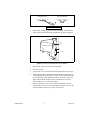
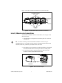
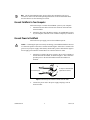
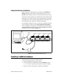
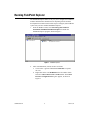
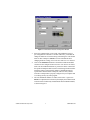
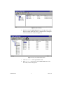
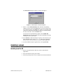
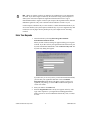
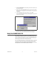
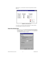
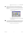
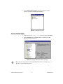
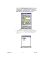
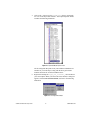
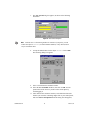
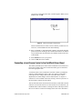
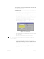
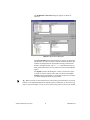
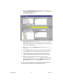
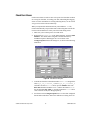
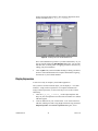
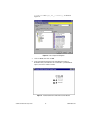
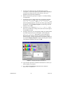
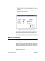
READ ME FIRST
SETTING UP YOUR LOOKOUT™ SCADA STARTER KIT
This document explains how to install and configure your Lookout
SCADA kit, which includes the following components:
•
Lookout 4.0 development software with 50 I/O points
•
FP-1000 network module
•
FP-AI-110 8-channel analog input module
•
FP-DI-330 8-channel universal discrete input module
•
FP-DO-400 8-channel 24 VDC discrete output module
•
PS-2 power supply
•
Three FP-TB-1 terminal bases
•
Accessories: RS-232 cable, 35-mm DIN rail, screwdriver
•
FieldPoint software: configuration utility and server
•
Additional documentation: Getting Started with Lookout, Lookout
Developer’s Manual, FP-1000/1001 User Manual, operating
instructions for each FieldPoint module, FieldPoint Server online help,
Lookout online PDF Lookout Object Reference Manual, and Lookout
online help
Hardware Setup
This section describes how to set up the FieldPoint I/O hardware and
connect it to your computer serial port.
Note Complete hardware installation instructions are included in the operating
instructions for each FieldPoint module.
Install Network Module and Terminal Bases onto DIN Rail
Follow these steps to install the network module and terminal bases onto
the rail:
1.
Use the screwdriver blade to open the DIN rail clip on the FP-1000
module to the unlocked position, as shown in Figure 1.
FieldPoint ™, Lookout ™, National Instruments™, and ni.com™ are trademarks of National Instruments Corporation. Product and company names are
trademarks or trade names of their respective companies.
322014B-01
© Copyright 1998, 2000 National Instruments Corp. All rights reserved.
March 2000
Rail Clip Locked
Rail Clip Unlocked
Figure 1. DIN Rail Clip
2.
Hook the lip on the rear of the FP-1000 onto the top of the DIN rail,
and press the FP-1000 down onto the DIN rail, as shown in Figure 2.
Local Bus
Connector
Lip
35 mm DIN Rail
Cover
Press
Figure 2. Installing the Network Module onto the DIN Rail
SCADA Starter Kit
3.
Slide the FP-1000 to the left end of the DIN rail.
4.
Lock the rail clip.
5.
If a protective cover is installed on the FP-1000 connector, remove it.
6.
Install each FP-TB-1 terminal base onto the DIN rail in the same way
you installed the FP-1000 network module. As you install them, slide
each terminal base along the DIN rail until its local bus connector is
firmly mated with the connector of the terminal base or network
module adjacent to it, as shown in Figure 3.
7.
Place the protective cover over the local bus connector of the last
terminal base on the rail. If you did not find the protective cover on the
network module, locate it in your bag of accessories.
2
www.ni.com
Figure 3 shows the assembled terminal bases and network module.
Local Bus Connectors
Firmly Mated
Protective
Cover
DIN Rail
Rail Snaps
Locked
Figure 3. FP-1000 Network Module and FP-TB-1 Terminal Bases
Install I/O Modules onto Terminal Bases
To install the I/O modules onto the terminal bases, refer to Figure 4 and
follow these steps:
1.
Align the FP-AI-110 alignment slots with the guide rails on the first
terminal base.
Note The order in which you mount the FieldPoint modules is reflected in your
configuration file. For your setup to exactly mirror the example program detailed in this
document, make sure you mount your modules in the same order.
2.
Press firmly to seat the FP-AI-110 on the terminal base. The terminal
base latch locks the FP-AI-110 into place when it is firmly seated.
3.
Repeat this procedure to mount the FP-DI-330 and FP-DO-400
modules on the second and third terminal bases.
Key
Latch
Alignment
Slot
Guide Rails
I/O Module
Terminal Base
Figure 4. Module Installation Diagram
© National Instruments Corporation
3
SCADA Starter Kit
Note The SCADA installation may not use all the parts included in your bag of
accessories. Refer to the FP-1000 Operating Instructions for more information about
how and when to use the remaining accessories.
Connect FieldPoint to Your Computer
Follow these steps to connect the FieldPoint system to your computer:
1.
Attach the RS-232 cable to the RS-232 connector on the FP-1000
network module.
2.
Attach the other end of the RS-232 cable to an available RS-232 port
on your computer, and make a note of which COM port you connect to.
Connect Power to FieldPoint
Follow these steps to apply power to the FieldPoint system.
Connecting the power incorrectly can damage your FieldPoint hardware. Be sure
to connect the positive lead to the V terminal and the negative lead to the C terminal. The
grooves on your power supply cable identify which lead is positive and which is negative.
Do not apply power until the terminal bases are connected to the FP-1000.
Caution
1.
Attach the two leads of the power supply to the V and C terminals of
the FP-1000 network module, as shown in Figure 5. This connection
provides power to the network modules and all I/O modules in
the bank.
+
To Power Supply
V V
V
To Adjacent Terminal Base
(Optional Connection)
C C
–
Grooves
C
Figure 5. Connecting to the V and C Terminals of the FP-1000
2.
SCADA Starter Kit
Connect the power cord to the power supply and plug it into an
electrical outlet.
4
www.ni.com
Completed Hardware Installation
Figure 6 shows the completed setup. You should see the POWER and
READY LEDs lit on each module. If these LEDs are not lit, or if the
STATUS LED is blinking, check your connections and baud rate setting.
The FP-1000 network module is pre-configured for network address 0 and
a baud rate of 115.2 kbaud. In most cases, you should not need to modify
this configuration. If you do require a different address or baud rate, refer
to the FP-1000 network module user manual for instructions.
If your hardware settings are correct, you may have to adjust the baud rate
of your computer’s serial port. Select Start»Settings»Control Panel to
access your Windows system utilities. In Windows NT, adjust the baud rate
using the Ports utility. In Windows 98/95, use the System utility and adjust
the Ports item under the Device Manager tab.
RS-232
Cable
FP-1000
FP-AI-110
FP-DI-330
FP-DO-400
Power Supply
Figure 6. Completed FieldPoint Hardware Setup
Installing FieldPoint Software
Follow these steps to install the FieldPoint software:
1.
2.
Insert the FieldPoint CD into your CD drive.
If the CD does not run automatically, select Start»Run and enter
N:\SETUP, where N represents your CD drive. Then, click on OK.
3.
© National Instruments Corporation
Follow the onscreen instructions to complete the installation.
5
SCADA Starter Kit
Running FieldPoint Explorer
The FieldPoint Explorer makes it easy for you to configure the FieldPoint
modules and define the channel items for importing into the Lookout
development environment. Follow these steps to configure your FieldPoint
system after you have installed FieldPoint Explorer:
1.
From the Windows menu, select Start»Programs»National
Instruments FieldPoint»FieldPoint Explorer to launch the
FieldPoint Explorer program, shown in Figure 7.
Figure 7. FieldPoint Explorer
2.
SCADA Starter Kit
Add a communication (comm) resource as follows:
a.
Click on the + sign next to IA Server with OPC to expand
the view.
b.
Right-click on the word FieldPoint in the left window frame
and select Add a comm resource to this server. The Comm
Resource Configuration dialog box appears, as shown in
Figure 8.
6
www.ni.com
Figure 8. Communication Resource Configuration Window
3.
Select the COM port that you are using. The FieldPoint system is
pre-configured for a baud rate of 115200. Therefore, you should not
change the baud rate or timeout setting in the dialog box. The default
name for this COM port is FP Res. For more information about
changing baud rate settings, refer to the FP-1000/1001 User Manual.
4.
Click on the Find Devices button to find all the FieldPoint modules
connected to the configured comm resource. If no devices are found,
make sure the FieldPoint hardware is powered on and is connected to
the specified COM port. Make sure the switch settings for the baud rate
match the settings on the network module. If FieldPoint Explorer
reports that it cannot bind the COM port, make sure that you have
selected a COM port that is properly configured in your computer and
is not being used by any other program.
5.
After the FieldPoint modules are found, click on the + sign next to
FP Res to expand the device hierarchy and display the modules found
on the network. The hierarchy should include four FieldPoint modules,
as shown in Figure 9.
© National Instruments Corporation
7
SCADA Starter Kit
Figure 9. Device Hierarchy
6.
Double-click on the FP-DO-400 @3 device. The right section of the
Explorer window displays the items, or channels, that are configured
for the selected device, as shown in Figure 10.
Figure 10. Items of the FP-DO-400 @3 Device
SCADA Starter Kit
7.
Click on Channel 0 in the right window frame.
8.
With Channel 0 selected, click on the Write Value button of the
I/O toolbar, as shown in Figure 10.
8
www.ni.com
The Item Write dialog box appears, as shown in Figure 11.
Figure 11. FieldPoint Explorer Item Write Dialog Box
9.
Enter “1” in the Value (Boolean) field to turn the corresponding
channel on. Then, click on the Write button. The current status of the
write channel appears in the Status field, and the corresponding LED
(channel 0) on the FP-DO-400 lights up. When you are done writing
the value to the item, click on the Done button.
You can also test digital and analog inputs. Select FP-DO-400,
Channel 0 in the left window frame, and start monitoring by clicking
on the green arrow in the toolbar.
10. Select File»Save. When the dialog box appears, enter a name for your
IAK configuration file, such as demo.iak, and note the full path to
that file for use when you build your Lookout example application.
11. Exit the FieldPoint Explorer application by selecting File»Exit.
Installing Lookout
Installing from the CD
1.
Before you install Lookout, make sure you have shut down all
applications.
2.
Insert the Lookout CD into your CD drive.
3.
Follow the prompts on the screen to complete the Lookout installation.
© National Instruments Corporation
9
SCADA Starter Kit
The Lookout CD has autorun capability. If for some reason the autorun fails
to start the CD installation routine, follow these instructions:
1.
Click on the Start icon in the taskbar and select Run.
2.
Enter N:\SETUP, where N represents your CD drive. Then, select OK.
•
Use Browse to enter the name of an alternate directory, or select
Next to accept the recommended directory name.
•
Make sure you select the option to install Lookout’s ODBC driver
if you want to be able to access Lookout’s internal Citadel
database.
•
On a Windows NT system, if you want to be able to block
authorized users from using <Alt-Tab> to gain access to
applications other than Lookout, make sure you install the
optional NT keyboard driver from the list of optional components.
Installing Lookout from Floppy Diskettes
If the computer you want to install Lookout on does not have a CD drive,
follow these instructions for installing the software:
1.
Prepare about two dozen blank diskettes: 3.5-inch, 1.4 MB. Label each
diskette as Disk1, Disk2, and so on.
2.
On another computer with a CD drive and diskette drive, copy the files
from the individual DiskN subdirectories on the CD onto the
appropriately labeled 3.5-inch floppy diskette. Do not copy the DiskN
directory itself onto your diskettes. Copy only the contents of each
directory.
3.
On the computer where you want to install Lookout, insert the diskette
labeled Disk1 and run the setup.exe program from the diskette.
4.
Follow the installation instructions on the screen.
Registering Lookout
Be sure to register Lookout to receive your permanent unlock code. As an
unregistered package, Lookout is limited to 50 I/O points and only runs for
30 days, with no client.
If you are installing Lookout as an upgrade to an earlier version, you will
have already provided registration information, and Lookout will open with
a request for you to log in.
If this is your first installation of Lookout on the computer you are using,
or if you have lost or corrupted your registration information, then the first
time you launch Lookout, it prompts you for registration information.
SCADA Starter Kit
10
www.ni.com
Note When you register Lookout, you unlock it for permanent use at your appropriate
I/O count. If you do not register Lookout by the end of the 30 day period, it lapses to a
demo system. You must complete the registration form and mail or fax a copy to
National Instruments to register Lookout. Upon receipt of the registration form, National
Instruments generates a key code to unlock Lookout and faxes or mails it to you.
Lookout requires a hardware key in some countries. Contact National Instruments if you
are not sure whether your system requires a hardware key. If you were supplied a key with
Lookout, be sure to plug it into the parallel port on your computer before activating
Lookout.
Enter Your Keycode
1.
Launch Lookout by selecting Start»Programs»National
Instruments Lookout»Lookout.
When you start Lookout, a dialog box appears asking you to register
Lookout. If you have sent in your registration form and received your
keycode from National Instruments, click on Enter new keycode. The
keycode entry dialog box appears.
If you have not yet received your key code from National Instruments,
you can enter your registration data later. Click on Continue
unregistered use and Lookout will inform you that you have not
registered your package yet. Select OK to launch an unregistered
version of Lookout.
2.
Enter your name in the Name field.
3.
Enter the Organization name exactly as it appears on the key code
reply sent in response to your registration, including punctuation
marks. This text is used in combination with the key code, so it must
be exact.
© National Instruments Corporation
11
SCADA Starter Kit
4.
Enter the Serial Number of your package. (This can be found on your
key code reply form.)
5.
Enter your 12-character Keycode. The key code is not case sensitive
and you can leave the hyphens out. Notice that there are no spaces near
the hyphens.
6.
After completing the entries, press <Enter> or select OK.
If you enter the information correctly, Lookout appears on your screen
with no process running.
If you are certain that you typed the information correctly and Lookout
does not accept it, call National Instruments technical support.
Using Your SCADA Starter Kit
After you have installed and configured your FieldPoint hardware and
software and the Lookout software, you are ready to begin using your new
system. The following introductory example is intended to help you get
started using your system in the shortest possible time.
For a more detailed introduction to Lookout and all its features, consult the
Getting Started With Lookout manual. This manual introduces all the
Lookout tools, discusses the design of Lookout client and server processes,
and explains how to use the advanced features of Lookout.
SCADA Starter Kit
12
www.ni.com
In this exercise, you will build a Lookout control panel that resembles
Figure 12.
Figure 12. Lookout Control Panel
If you choose, you can add switches and indicators for eight channels,
use custom graphics, and make other alterations.
Create Your Control Panel
1.
© National Instruments Corporation
Start Lookout by selecting Start»Programs»National Instruments
Lookout»Lookout. Create your control panel by selecting File»New.
The Create Process dialog box appears.
13
SCADA Starter Kit
2.
Name your process by entering SCADA_Starter in the Process Name
field.
For more information on the options contained in any dialog box, click on the
Help button to view the online help. Or, you can access the online help by selecting
Help»Contents from the Lookout menu. The Lookout online help contains information on
all the Lookout objects, features, and services, as well as a developer tour that includes a
brief tutorial.
Tip
3.
Click on OK. The New Control Panel dialog box appears, as shown
in the following illustration.
Figure 13. Creating a New Control Panel in Lookout
4.
Title your control panel Lookout SCADA Starter Kit Control
Panel, and select a new background color if you want. Click on OK
to create the new panel.
Notice that the status bar at the bottom of the Lookout workspace turned yellow when
you created your new process. This signals that Lookout is in Edit mode. If you find you
cannot create an object or you have trouble with completing some of the steps, check to see
if Lookout is in Edit or Run mode. You can change modes by pressing <Ctrl-Space>.
Tip
5.
SCADA Starter Kit
Adjust the size of your new panel if necessary.
14
www.ni.com
6.
Select Object»Object Explorer. The Object Explorer window
appears, as shown in the following illustration.
Figure 14. Lookout Object Explorer
Create a Switch Object
1.
Right-click on your SCADA_Starter process and select New Object.
2.
Select FieldPoint from the Drivers folder in the dialog box that
appears, as shown in Figure 15.
Figure 15. Creating a FieldPoint Driver Object in Lookout
Note Make sure that you have exited FieldPoint Explorer before you import your .iak
file with the Lookout FieldPoint object.
© National Instruments Corporation
15
SCADA Starter Kit
3.
Fill out the Create FieldPoint Secondary dialog box as shown in
Figure 16. The IAK Configuration File field directs the software to
the location of the .iak file you created when you installed your
FieldPoint hardware. Enter the path to the demo.iak file, or use the
Browse button if you do not remember the complete path.
Figure 16. Create FieldPoint Secondary Dialog Box
4.
Click on OK. When you add this object to your process, the tree view
of the SCADA_Starter process in the Object Explorer expands to
show the new FieldPoint1 object, as shown in the following
illustration.
Figure 17. New Object in Object Explorer
SCADA Starter Kit
16
www.ni.com
5.
Click on the + sign next to the FieldPoint1 object to expand the
tree view of the object data members. Your Object Explorer should
resemble the following illustration.
Figure 18. Expanded Object Explorer View
All the configured data points from your FieldPoint installation are
available to you in this object, along with the more general data
members built into the Lookout FieldPoint driver.
6.
Right-click and drag the FP_DO_400_3.Channel_0 data member to
your control panel. When you release the mouse button, a dialog box
appears. Select Create Control»Switch, as shown in the following
illustration.
Figure 19. Selecting Switch Object
© National Instruments Corporation
17
SCADA Starter Kit
7.
The New switch dialog box appears, as shown in the following
illustration.
Figure 20. New Switch Dialog Box
Note Lookout uses 1 as the starting number for controls. If you prefer, you can
rename the object to Switch0 (to match channel numbers) or any other useful or
easy-to-remember name.
8.
Accept the default values for the object Switch1. Click on OK.
The following dialog box appears.
9.
Select a switch from the standard switches.
10. Select the Use as Default checkbox, then click on OK. You can
position the switch wherever you like on the control panel by
click-dragging it.
11. Add a label for the column of switches, and a label that shows the
channel your switch is controlling. Right-click in your control panel,
and select Insert»Text/plate/inset. In the dialog box that appears,
SCADA Starter Kit
18
www.ni.com
you can type a text label and set how your label appears. When you are
finished, click on OK.
Figure 21. Switches Arranged on Control Panel
Notice also that to have two lines of text as shown, you must use two
text boxes, each with different fonts and formatting.
12. Press <Ctrl-Shift> to leave Edit mode. Operate your switch using the
pointer. Notice that clicking on the switch turns Channel 0 on and off
on your FP-DO-400, as indicated by the Channel 0 LED on the front
of the module.
13. Select File»Save to save your process.
14. Click on OK, then click on Save.
Connecting a Local Source Control to the FieldPoint Driver Object
The control you made uses a remote source connection. You can also use a
local source control with a direct connection. Both types of connections
have their appropriate uses.
A Lookout remote source connection is interactive. When you adjust the
control, Lookout adjusts the object or PLC the control is connected to.
If the object or PLC changes from some cause other than a control
adjustment, the control changes value to match the PLC or object it is
connected to. You can think of the value as being “owned” by the PLC or
the object that is connected to the control.
You can also make direct connections from Lookout, in which the Lookout
control is its own local source for its value. In this sort of connection, you
can think of the Lookout control as “owning” the value. If the object or PLC
this sort of control is connected to changes from some cause other than a
© National Instruments Corporation
19
SCADA Starter Kit
control adjustment, Lookout will restore the local value of the control to the
PLC or object as soon as it can.
You need only two switches for this demonstration exercise, but you can
use as many as eight.
1.
Press <Ctrl-Space> to return to Edit mode (the status bar at the bottom
of the Lookout workspace should turn yellow).
2.
<Ctrl>-click on your first switch and drag it to make a new switch
object. This newly created switch is automatically named Switch2
(assuming you left your first switch named Switch1).
This new switch is a new object, but it has the same URL connection
to the Channel 0 data member as the first switch you created. In the
following steps, you will change this connection.
3.
Right-click on your new switch, and select Object Properties.
The following dialog box appears.
Figure 22. Revise Switch Dialog Box
4.
Select the Local option in the Position source section of the dialog
box. Click on OK.
5.
Place your new switch below the first switch you created.
Select the switches and use the options under the Arrange menu to get a neat
arrangement quickly.
Tip
6.
Connect the FieldPoint object data member to the new switch.
Lookout object data members are used to read from and write to the
equipment you are controlling. For a detailed explanation of Lookout
data members, see the section How Lookout Works in the Lookout
online help.
To connect to a data member in Lookout, right-click on the
FieldPoint1 object in the Object Explorer, and select Edit
Connections.
SCADA Starter Kit
20
www.ni.com
The FieldPoint1 connections dialog box appears, as shown in
Figure 23.
Figure 23. Edit Connection Dialog Box
The Select member portion of this dialog box is where you choose the
data member you want to connect to. All the available (writable) data
members are displayed in the left window. Existing connections are
shown in the right window. (The Poll Rate data member shows as
being connected because you set it when you created your FieldPoint
object.)
The Signals section of the dialog box is where you select the object
or value you want to connect to the value you choose in the Select
member section of the dialog box. Notice that you can select an object
or control running anywhere on your network.
When you create or edit connections in Lookout, always select the object you want to
connect to. For detailed information on making Lookout connections, see the Connecting
Objects section of Chapter 4, Using Lookout, in the Getting Started with Lookout manual.
Tip
© National Instruments Corporation
21
SCADA Starter Kit
7.
Fill out the Select Member field of the dialog box as shown in the
following illustration by highlighting FP_DO_400__3.Channel_1 in
the Writable members field.
8.
Click on the Select button to select the FP_DO_400__3.Channel_1
data member. Fieldpoint1.FP_DO_400__3.Channel_1 (or as
much of the string as there is room for) appears next to the yellow field
in the center of the dialog box.
9.
Select Switch2 from the Signals Tags list. Select the (implicit)
data member.
10. Click on Paste and then Accept to create the new logical connection.
11. Click on Quit when you have finished making your connections.
12. Leave Edit mode and try your new switch. Notice the LED for
Channel 1 on the FP-DO-300 responds to the control you created.
13. Return to Edit mode and create a label for your new switch.
<Shift>-click on the label Channel 0, and drag the text next to the
new switch. Right-click on the label, select Display Properties, and
change the text to Channel 1. Click on OK.
For more detailed information on connecting objects and data members,
see the section Using Lookout in the Lookout online help.
SCADA Starter Kit
22
www.ni.com
Check Your Aliases
Lookout uses aliases to make it easier to keep track of what data members
are serving for what data, for scaling your data, and making data logging
easier. For more information on creating and using aliases, see the section
Using Lookout in the Lookout online help.
When you imported the information from your FieldPoint .iak file,
Lookout automatically accepted alias names and scaling data from the file.
Use the Lookout database to check your aliases and scaling values.
1.
Make sure your Lookout process is in Edit mode.
2.
Right-click on FieldPoint1 in the Object Explorer, and select Edit
Database. The default names assigned to the data members by
FieldPoint Explorer should appear as a list of aliases in the
Configured points field of the dialog box, as shown in the following
illustration.
Figure 24. Edit Database Dialog Box
3.
To make sure that the Lookout data member AI001.00 is assigned the
alias FP_AI_110_1.Channel_0, select FP_AI_110_1.Channel_0,
and make sure that AI001.00 shows up in the Member field. The
Raw units minimum should be set to 0 and the maximum to 65535.
Set the minimum Eng. units to 0 and the maximum to 0.021. These
value selections scale your data appropriately.
4.
Scroll down in the Configured points list to see the other configured
data members and aliases. Notice the differences in dialog boxes for
© National Instruments Corporation
23
SCADA Starter Kit
numeric and logical data members. The following illustration shows
the alias information for FP_DO_400_3.Channel_0.
Figure 25. Checking Values for FP-DO-400 Channel 0
The Lookout database keeps track of your data automatically. As you
can see from the fields in the Edit Database dialog box, you can scale
and filter data, set alarm points, set logging preferences, and more, by
editing your process database.
5.
Click on Quit when you have finished checking or editing your aliases.
See the Lookout documentation for complete information on getting
the most out of your Lookout database.
Display Expressions
You are now ready to complete your SCADA application.
After you have created a Lookout object, you can display it—or its data
members—using Lookout expressions. For complete information on
using Lookout expressions, see the section Expressions in the Lookout
online help.
SCADA Starter Kit
1.
Click on FP_DO_400__3.Channel_0 in the Object Explorer and
drag it to your control panel next to the switch for Channel 0. A default
indicator appears.
2.
Create an indicator for your second switch. <Ctrl>-click on the first
indicator, and drag it to make a copy. Right-click on the copy and select
Object Properties. In the Revise expression dialog box, select
24
www.ni.com
FieldPoint1 and FP_DO_400__3.Channel_1, as shown in
Figure 26.
Figure 26. Revise Expression Dialog Box
3.
Click on Paste, then click on OK.
4.
Your front panel should now look something like Figure 27.
Remember that your indicators are connected to your FieldPoint
object, not to the Lookout switches.
Figure 27. Lookout Control Panel with Switches and Indicators
© National Instruments Corporation
25
SCADA Starter Kit
5.
To check your connections, leave the Edit mode by pressing
<Ctrl-Space>. You can now operate your switch controls. If flipping a
switch does not change the color of the indicator, check your
FieldPoint connections and configuration.
6.
Return to Edit mode by pressing <Crtl-Space> to continue building
your application.
7.
To display the status of digital inputs from your FP-DI-330 module,
create expressions as you did in Step 1 for the DI data members,
FP_DI_330__2.Channel_0 and FP_DI_330__2.Channel_1. You
can use the standard indicator, or choose your own by right-clicking on
the indicator, selecting Display Properties, and choosing a different
indicator. Click on OK.
8.
Label the new set of indicators FP-DI-330 at address 2. Once
again, for your indicators to change color, there must be some input to
your FieldPoint module.
9.
To display values from your Analog input module, put a different kind
of Lookout expression on your control panel. Click and drag the
FP_AI_110_1.Channel_0 data member to your control panel.
Because this data member is numeric instead of logical, a digital
indicator appears. To change the appearance of the display, right-click
on it and select Display Properties. Complete the dialog box as shown
in the following illustration, then click on OK.
Figure 28. Configuring a Display for the FP-AI-110
10. Copy and edit expressions to add all the other FP-AI-110 values you
want to display on your panel.
11. Select Insert»Text/plate/inset, and label the new indicators
FP-AI-110 at address 1.
SCADA Starter Kit
26
www.ni.com
12. Add an update indicator to your panel by dragging the Update data
member to the panel. You can continue to add labels as you create new
expressions.
13. Add a communications failure indicator by dragging the CommFail
data member to your control panel.
14. Using the labeling and other features of Lookout, your completed
control panel might look something like Figure 29.
Figure 29. Control Panel with Switches and Indicators Added
For your Lookout control panel to function completely, you must have your
FieldPoint modules connected to your computer and configured, and you
must also have electrical signals connected to the input modules.
You can modify this example to create your own FieldPoint control system,
or use the techniques illustrated to build your SCADA control from scratch.
Where to Go from Here
Now that your starter kit is set up, refer to the hardware and software
documentation that came with your kit for help with building and running
your own application.
The Getting Started with Lookout manual explains how to install Lookout
and how to get started building your own control systems. In particular,
Chapters 2 through 5 equip you with almost everything you need to begin
building your own SCADA application.
The Lookout Developer’s Manual is a more detailed reference to the
features and functions of Lookout. You can refer to this manual for detailed
explanations of specific issues.
© National Instruments Corporation
27
SCADA Starter Kit
The many different Lookout object classes, including the National
Instruments FieldPoint driver, are documented in the online help file, and
in the Lookout Object Reference Manual, which is supplied in PDF format
in a file called ObjectRef.pdf, installed in the Documentation folder of
your Lookout directory.
For information about your FieldPoint hardware and software, refer to the
FieldPoint network module user manual. For help with FieldPoint
Explorer, refer to its online help. For help with the FieldPoint modules,
refer to the individual module operating instructions.
Thank you for choosing National Instruments Lookout and FieldPoint for
your industrial automation needs.