1
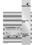
Model Number:V2 User Manual Package Contents 2 4 5 B 3 A 41 1 6 42 44 43 7 8 12 14 13 10 11 9 15 23 17 28 22 26 21 30 31 18 24 19 16 20 34 32 1 1 33 2 3 3 3 4 - + + - - - + 3 4 25 27 40 38 36 2 2 2 37 1 1 4 4 + 35 29 39 Parts Identification&Fitting Diagrams Fig.1 A Fig.4 F C C B B A Fig.5 A B F C D E Fig.9 Fig.10 20mm Fig.8 A 10mm Fig.11 A A X X Parts Identification&Fitting Diagrams Fig.3 Fig.2 A B C Fig.7 Fig.7.1 Fig.6 Fig.2.1 B Fig.3 Fig.7 A D Parts Identification&Fitting Diagrams Fig.12 - 1 2 + - Trailer Front B + 3 4 + - A Fig.13 6.5’’ (Min) 3.4’’ (Min) 71’’ to 99’’ (Max) Table of Contents Package contents Page 2 Introduction Page 3 Intended use Page 3 Specifications Page 3 Installation - safety guidelines Page 3,4 Installation - mechanical components Page 4,5 Installation - electrical/electronic components Page 5,6 Operation safety guidelines Page 6,7 Operation - motor units Page 7,8 Operation - remote control handset Page 8,9 Operation - electronic control unit Page 9 Operation - getting started Page 9,10 Operation - hitching and unhitching Page 10 Maintenance Page 10,11 Trouble shooting Page 11,12 Important information Page 12 Disclaimer Page 12 page 1 Package Contents (Fig.A) 1 1 Motor unit (A) 2 1 Motor unit (B) 3 1 Main cross bar 4 1 Cross actuation centre bar 5 2 Cross actuation insert bars 6 1 Engagement tool 7 4 Chassis stop blocks 8 4 Chassis hanging bracket 9 2 Carrier plate 10 8 5mm shim for narrow chassis 11 2 Cross member support bracket 12 2 Bar support hanging bracket 13 1 Convoluted cable trunking 14 2 Positive (+) red motor cable 15 2 Negative (-) black motor cable 16 1 Positive (+) red battery cable 1.8m including fuse holder & 80A fuse 17 1 Negative (-) black battery cable 1.6m 18 4 Bolts M12x30 19 4 Bolts M12x40 20 4 Bolts M12x50 21 12 Nuts M12 22 12 Spring washers M12 23 24 Plain washers M12 24 8 Bolts M10x40 25 8 Nuts M10 26 16 Plain washers M10 27 8 Spring washers M10 28 2 Battery terminal connector 6mmØ 29 4 Battery terminal connector 8mmØ 30 6 Cable spade connectors 31 20 P-clip screws - M4x15 32 10 Cable trunking P-clips 19.2mm 33 10 Cable P-clips 10.4mm 34 3 Cable number markers (1,2,3,4) 35 3 Cable polarity markers (+,-) 36 4 Motor unit cable ties 8x400 37 10 Cable ties 2x70 38 1 Battery isolation switch, cover & key 39 2 Rubber isolation shell for battery isolation switch 40 2 Roller distance spacers 20x20 41 1 Electronic control unit 42 1 Remote control handset with lanyard 43 1 Remote control handset wall holder 44 1 User manual page 2 Introduction Congratulations on choosing the Royal Easi-Move travel trailer manoeuvring system. This has been produced according to very high standards and has undergone careful quality control procedures. Simply by using the remote control handset you can move your trailer effortlessly into any position required within operating guidelines. Soft start and soft stop technology allows you to manoeuvre your trailer even more accurately without any sudden starts or stops. Before proceeding with installation and starting to use the manoeuvring system, please read this manual very carefully and be aware of all the safety instructions! The owner of the travel trailer will always be responsible for correct use. Keep this manual inside your travel trailer for future reference. The Easi-Move V2 manoeuvring system consists of two 12V motor-power rollers, a 12V electronic control unit and a remote control handset. To function, the motor-powered rollers must be engaged against the tires of your travel trailer. The supplied cross actuation device enables you to engage both rollers at the same time from one side of your trailer. Once this is done the manoeuvring system is ready for operation. The remote control will allow you to move your trailer in the required direction. Intended Use The Royal Easi-Move V2 manoeuvring system is only suitable for single or tandem axle trailer’s up to 4000 lbs. Depending on the weight of the trailer, the manoeuvring system cannot overcome obstructions that are more than aproximately 1½ ” in height without assistance (please use wedges as a ramp). Specifications Specifications Designation Operational Voltage Average Current Consumption Maximum Current Consumption Speed Weight Permissible Overall Weight Permissible Overall Weight on 15% Gradient Minimum Width (trailer) Maximum Width (trailer) Maximum Tyre Width Power Source (deep cycle battery) Royal Easi-Move V2 12 Volt DC 20 Ampere 100 Ampere approx.13cm per sec. approx. 89 lbs (exclusive of battery) 4000 lbs 2750 lbs 71” 99” 8” 12V 105Ah (recommended), 12V 85Ah (minimum) Installation Safety Guidelines Read this User Manual carefully before installation and use. Failure to comply with these rules could result in serious injury or damage to property. These symbols identify important safety precautions. They mean CAUTION! WARNING! SAFETY FIRST! IMPORTANT INFORMATION! Before starting installation under the trailer: Check the towing load of your vehicle and the gross weight of your trailer in order to establish whether they are designed for the additional weight. The manoeuvring system itself has a weight of about 81 lbs. Check that the trailer is disconnected from the battery supply and the mains electrical supply. Only use adapters and accessories that are supplied or recommended by the manufacturer. Check that the tires are not over worn and have the same size and design. Make sure that the tire-pressures are correct to the manufacturer’s recommendation. Make sure the chassis is in good condition without any damage and is free from rust, dirt etc. Stop work immediately if you are in doubt about the assembly or any procedures and consult one of our engineers (Please refer to contact information on the last page of this manual). page 3 Locate the battery isolation switch to be accessible at all times when parking and moving the trailer. Do not remove, change or alter any parts of the chassis, axle, suspension or brake mechanism. Do not operate the unit if you are under the influence of drugs, alcohol or medication that could impair your ability to use the equipment safely. Installation - Mechanical Components FOR PROFESSIONAL INSTALLATION ONLY. These instructions are for general guidance. Installation procedures may vary depending on trailer type. Working under a vehicle without appropriate support is extremely dangerous! Place the trailer on a hard, level surface. The use of a lifting ramp or an assembly pit is ideal for access and personal safety. Unpack all the components and check for the presence of all parts (see package contents list). Write down, on the guarantee card and in the back of this manual, the 10-digit serial number (this is located on an aluminium plate on the side of one of the motor units). Clean the area of your chassis where you need to mount all components to ensure a good fitting. Make sure the trailer is prepared for installation. Check before installation that important areas, such as drains/spare tire etc. do not cause any obstruction to the function of the manoeuvring system. Ensure both rollers are in the DISENGAGED position (Fig.10A), as the unit will not fit correctly otherwise (Note: when fully disengaged, the pointer in the beginning of the yellow area). Loosely assemble the left hand motor unit (1), right hand motor unit (2) and main cross bar (3) (see Fig.1). The nuts (Fig.1B), on the cross bar (3) to secure both motor units, must be no more than finger-tight at this stage. Note: In principle, the unit should be fitted in front of the trailer road wheels, but if fitting in this position is not possible because of obstacles or a too high hitch ball weight, it is permissible to fit it to the rear of the wheels by rotating the whole assembly (Fig.1) by 180° degrees. Loosely fit the two chassis hanging brackets (8)to the chassis (Fig.2 & Fig.6) by using bolts M12 x 40 (19), nuts M12 (21), spring washers(22) and plain washers (23). Place suitable quatity of 5mm shims (10) between the two chassis hanging brackets (8), and then loosely fit the carrier plate (9) to the chassis hanging brackets and 5mm shims by using bolts M12 x 50 (20), nuts M12 (21), spring washers (22) and plain washers (23), choosing suitable holes in the chassis hanging brackets (8) to fix the carrier plate to make sure the aluminum drive roller of the pre-mounted manoeuvring system approximately on the same altitude as the center(axle) of the caravan wheel. Loosely fit the bar support hanging bracket (12) to the carrier plate by using bolts M12 x 30 (18), nuts M12 (21) , spring washers (22) and plain washers (23). Nuts must be no more than finger-tight. If you are NOT using the clamp bracket option and are bolting the bracket to the chassis you will need to assemble the bracket with the mover attached for positioning. Ensure the mover is fully disengaged and position the mover 20mm (3/4”) away from the surface of the centre each tire (Fig.10). Two 20mm spacers (40) are provided. Mark the chassis where you need to drill the holes and drill the holes. Remove the mover from the bracket and bolt the bracket to the chassis. Assemble the pre-mounted manoeuvring system to the steel chassis clamp plates (Fig.2 & Fig.6) by using the cross member support bracket (11), bolts M10x40 (24), nuts M10 (25), spring washers (27) and plain washers (26). Nuts must be no more than finger-tight. Make sure that aluminium drive roller of the manoeuvring system is approximately on the same altitude as the centre (axle) of the trailer wheel. Adequate ground clearance: Please notice that the min. distance between the lowest line of manoeuvring system and ground is 4 ½”. Assemble the parts of the cross actuation bar (4 & 5) and connect them to the motor units (1 & 2) with the nylon nut and bolt (factory fitted) onto the cross actuation bar-connectors (Fig.1 & Fig.1A). Nuts must be no more than finger-tight at this stage. Make sure that the Main Cross Bar (3) and the Cross Actuation Centre Bar (4) are positioned in the middle of the trailer/ manoeuvring system (the centre of the bars is marked). page 4 With the main assembly is loosely fitted onto the chassis, slide the whole assembly along the chassis until the rollers are 20mm (3/4”) away from the surface of the centre each tyre (Fig.10). Two 20mm spacers (40) are provided. It is vitally important that each roller is at exactly the same distance away from the tyre. The whole assembly must be parallel to the trailer axle. Slide the motor units in or out of the cross bar (3) accordingly to ensure the roller will have the maximum possible contact with the tread of the tire. Ensure that the position of each motor unit does not obstruct shock absorbers (if fitted) and that the plastic gear cover (Fig.4F) is not too close to the surface of the tire. The minimum clearance when the drive units swivelled in is 10 mm. Fully tighten the four bolts (Fig.1B) on the Main Cross Bar (3) and the four bolts (Fig.1C) on Cross Actuation assembly (4 & 5). Fully tighten all the nylon nuts (21 & 25) on both clamping assemblies (Fig.2 & Fig.6). Tighten the M10x40 bolts to a 40Nm torque. Re-check the distance of 20mm (3/4”) from the rollers to the tires, the position of the aluminium rollers in addition to the surface of the tire and finally the distance between the gear cover (Fig.8) and the tires & shock absorbers (>10mm). If necessary, loosen the bolts and re-adjust the position of the assembly. The weight of the trailer must be on the wheels when doing this. Fix the Chassis Stop Blocks(7) next to the mounting brackets. Fix the bolts with a 40Nm torque, and then fix the nut with a 40Nm torque to keep the bolts on position. Re-check that all bolts/nuts have been tightened to the correct torque! The main mechanical components have now been installed. Installation - Electrical/Electronic Components Make sure the 12V supply from the battery and any mains electricity supply are disconnected. Remove battery cable terminals and disconnect any external electrical power before starting work. Find a suitable place for the Electronic Control Unit (41), such as a storage area, under a seat or a bed. Make sure this place is dry. The unit can be mounted on the bottom (horizontal) or on the wall (vertical). When choosing location, ensure that the antenna can be completely extended and cannot easily be damaged. Fix the Electronic Control Unit securely into position with four screws (31). Note: if the provided screws are not of suitable length or type for the desired location/material please substitute these as appropriate. Drill a 1” hole through the floor of the trailer approximately 5” or 6” away from the front of the control unit (41) terminals. Caution! Take extra care to avoid any chassis members, gas pipes and electrical wires! Route and connect the motor-cables in accordance with wiring diagram (Fig.12) (red = positive, black = negative). The wiring diagram (Fig.12 + Table.A (see below)) depicts the wiring route when installing the motor units in front of the wheels/axle towards the ‘A’ frame. Please refer to table B (below) for fitment of the motor units to the rear of the axle. Table . A FRONT OF AXLE FITTING Motor A Positive (+) cable to terminal 3 Motor A Negative (-) cable to terminal 4 Motor B Positive (+) cable to terminal 1 Motor B Negative (-) cable to terminal 2 Table . B REAR OF AXLE FITTING Motor A Positive (+) cable to terminal 2 Motor A Negative (-) cable to terminal 1 Motor B Positive (+) cable to terminal 4 Motor B Negative (-) cable to terminal 3 page 5 Mark the Motor Cables (14 & 15) for both motor units using the cable markers (34). The cables for the left and the right motor should have the same length. Avoid any loops. Connect the spade connectors (30) to the motors. Please note that the red cable is connected to the terminal under the moulded ‘+’ symbol on the weatherproof terminal cover. THE CONTROL BOX HAS A SINGLE OR TWIN AXLE MODE. ENSURE THE CONTROL BOX IS IN THE MODE BEFORE YOU USE THE EASI-MOVE. PEAL BACK THE BLACK TAPE ON THE FRONT OF THE HOUSING AND CHECK THE SWITCH IS IN EITHER SINGLE’S’ OR TWIN ‘T’ MODE. Remember to leave a small amount of slack cable near the motors to allow for their movement when the drive rollers are engaged. Use the large cable ties (36) to secure the motor cables to the motor. This ensures that there is no force and movement on the spade connectors or movement of the cables during transit. Route the motor cables along the underside of the trailer floor, inside the supplied Convoluted Trunking (13) (this will protect the electrical cables against sharp edges and dirt) and through the drilled hole. Secure the Cable Trunking (13) to the chassis or under body of the trailer by using the P-Clips (32) and screws (31). Once the motor cables are through the drilled hole next to the Control Unit (41), cut the cables, ensuring that they are same length. Remove approx. ¼” of the insulation from the ends. Fix the spade connectors (30) by using crimping pliers. A secure and good quality connection on each cable is essential. Attach the connectors to the terminals on the Control Unit (see wiring diagram Fig.12). Find a suitable place for the Battery Power Isolation Switch (38) which includes an external holder with hinged cover. Important: The switch must be mounted onto the exterior body of the trailer and be easily accessible from the outside of the trailer in case of any emergency. The switch must be mounted close to the location of the battery in order to keep the length of the battery cables to a minimum. Route the positive (+) power cable from the battery to the battery power isolation switch (38) and then further to the control unit (41). Route the negative (-) power cable directly to the control unit (41). No cables may be routed over the control unit! Again it is recommended to use the supplied trunking (13) to protect the cables against sharp edges. Attach the trunking with P-clips (32) and P-clip Screws (31). Cut the cables to an appropriate length and remove approx. ¼” of the insulation from the ends. Fix the spade connectors by using crimping pliers. A secure and good quality connection on each cable is essential. Connect the battery cables to the existing battery terminals (red = positive, black = negative). Two types of Battery Terminal Connector (28 & 29) are provided for use as appropriate. Caution! Make sure that you do not reverse the Positive (+) and Negative (-) connections. Incorrect connection (reverse polarity) will result in damage to the control unit. Finally, connect the Battery Cables (16 & 17) to the Control Unit (41). Seal the 1” hole in vehicle under body using plastic body sealant. Finally find a suitable place for the remote control handset wall holder (43) and fix this by the supplied screws (out of reach of children or other unauthorized people). Installation of the Royal Easi-Move V2 travel trailer manoeuvring system is now complete. Operation - Safety Guidelines Practice operating the manoeuvring system in an open area before using for the first time. This is to fully familiarise yourself with the handset / manoeuvring system operation. Before use, always check the manoeuvring system for any damage. When towing or moving the trailer please be aware, at all times, that ground clearance is reduced when the manoeuvring system has been fitted. page 6 Always ensure that children and pets are kept well out of the way during operation. When operating the manoeuvring system, ensure that no hairs, fingers or other body parts, clothing or any other objects carried on the body can become trapped by moving or rotating parts (e.g. drive rollers). In the event of malfunctions, chock the trailer immediately and turn off the main isolation power switch. To maintain signal strength, always make sure that, during manoeuvring, the distance between the remote control and the trailer does not exceed 16 feet. Due to the nature of a radio signal, it can get corrupted by external terrain or objects. So there may be small areas around the trailer where the quality of reception reduces, hence the manoeuvring system may stop momentarily. Always be aware that the manoeuvring system increases the weight of your trailer. So this reduces the payload of the travel trailer. Always make sure that the rollers are fully disengaged from the tires when the system is not in use. This is better for the tyres and for the system. Always make sure that the rollers are fully disengaged before towing/moving the trailer by vehicle or manpower. This can damage the tires, manoeuvring system and the towing vehicle. Always make sure that after you have finished using the manoeuvring system, the battery power isolation switch (38) is switched off and the key is removed and stored in a safe place (out of reach of children or other unauthorised people). If you don’t switch off, the battery will be discharged by the small ”standby” current. Always make sure that the remote control stored in a safe place (out of reach of children or other unauthorised people). If you don’t switch off, the battery will be discharged by the small ”standby” current. Do not rely on the manoeuvring system to act as a brake. Always securely chock your trailer after manoeuvring, before disengaging the drive rollers from the tires. Do not use the manoeuvring system as a support when jacking up the trailer, since this can damage the drive unit. Do not exceed the total Safe Working Load of 4000 lbs Laden Weight (GVWR). Depending on the weight of the trailer, the manoeuvring system cannot overcome all obstructions without assistance. Please use wedges as a ramp. All wheels and tires on the trailer must be of the same size and design. If tires are worn or new tires are fitted, the distance between the drive rollers and the tires may need readjusting (see “Installation - Mechanical Components”). Sensitive objects such as cameras, DVD-Players etc. must not be kept in the stowage box near the control unit or the motor cable. They can be damaged by the electromagnetic fields. Do not make any modifications on the trailer manoeuvring system (mechanical or electronically). This can be very dangerous! No warranty claim will be accepted and we cannot guarantee the function of the manoeuvring system if any modifications are made. We will not be liable for any damage whatsoever caused as a result of incorrect installation, operation or modification. Operation - Motor Units The Royal Easi-Move V2 manoeuvring system has two Motor Units (1 & 2). In general they are mounted in front of the axle of the trailer. Both units are identical but cannot be switched. Fig.4 A: Drive roller B: 12V motor C: Connection terminals (+ and -) D: Base unit E: Drive unit F: Gear cover page 7 In order to engage the rollers, fit the end socket of the engagement tool (6) on the spindle (Fig.9) on the right or left drive unit and turn the handle. Traction indicator label: The yellow-green-red traction indicator label (Fig.11A), on the side of each Motor Unit indicates if the roller is depressing the tire sufficiently to provide adequate traction. • If the pointer is in the yellow area – Rollers are not touching or depressing the tire sufficiently. • If the pointer is in the green area – Rollers should be connecting correctly to the tire (margin of ¼”) • If the pointer is in the Red area – Rollers are connected to the tire but in an extreme position. Seeing the red area of the indicator may mean that the tire of the trailer has insufficient air pressure or the drive unit has been knocked out of position and a visit to a workshop is required to reposition the assembly. Operation - Remote Control Handset The Remote Control handset (42) is powered by one PP3 9Volt battery, and is activated by moving the slide switch to “On”-I (Fig.5A). Once activated the green LED (Fig.5H) will illuminate and the directional controls can now be used. Fig.5 A = Slide switch (“Off” –O and “On”-I) B = Trailer forwards (both wheels rotate in forwards direction) C = Trailer reverse (both wheels rotate in reverse direction) D = Trailer left forwards (right wheel rotates in forwards direction) E = Trailer right forwards (left wheel rotates in forwards direction) F = Trailer left reverse (right wheel rotates in reverse direction) G = Trailer right reverse (left wheel rotates in reverse direction) When you drive straight forwards or reverse (press button B or C), it is also possible to adjust the direction by additional pressing button D or E (when driving forwards) or button F or G (when driving reverse). In addition, the ‘left forward’ (E) and ‘right reverse’ (F) buttons or ‘right forward’ (D) and ‘left reverse’ (G) buttons may be pressed at the same time to turn the trailer around on its own axis (without moving forward or backward). When you switch within 2 seconds from forward driving to reverse driving (and the other way around), a small delay of 1 second will appear to protect the electronics and the motors. The slide switch (Fig.5A) also acts as an “Emergency stop”. The remote hand set switches off: – after approx. 3 minutes, if no button is pressed – after approx. 5 minutes, if one of the movement buttons is permanently held down. The green LED goes off and the remote control handset is in the “stand-by” modes which means that there always will be used some current which causes the battery to go down. So always make sure the remote control handset is turned off by the slide switch. To reactivate the remote control, move slide switch to “Off” –O and then back to “On”-I after approximately 1 second. Error messages via the remote control handset: Error messages of the Royal Easi-Move V2 will be communicated via the remote control handset by the green LED (Fig. 5H) and a buzzer signal: LED off, no buzzer: remote control handset is turned off and also system is not activated LED continue on, no buzzer: remote control handset is turned on and system is activated and ready to use. Green LED is blinking (2 Hz), no buzzer: no communication between handset and control unit. This could be because of too much distance between remote control handset and control unit, or the battery isolation switch for manoeuvring system is not turned on or that there is a distortion signal disturbing the communication. As soon as connection is good again the green LED will be continue on and the system is ready to use. Green LED is blinking (2Hz) in combination with buzzer (2 times blinking, break, 2 times blinking, break etc.): Battery voltage too low (<10V). Battery needs to be recharged. Green LED is blinking (2Hz) in combination with buzzer (4 times blinking, break, 4 times blinking, break etc.): Battery Voltage too high (over charged). Try to discharge the battery by turning on a user (for example a lamp or water-pump). Green LED is blinking (2Hz) in combination with buzzer (6 times blinking, break, 6 times blinking, break etc.): Amp overload protection is activated. Wait about 60 seconds and try again. Green LED is blinking (4Hz), no buzzer: The internal 9V battery is near empty and needs to be replaced. Changing batteries in the remote control: When the battery is empty, it needs to be replaced. Open the rear cover of the handset via the small screw (Fig.7A). page 8 Take out the dead/old battery and dispose in the appropriate way. Install a new replacement battery (Fig.7.1). Make sure to use a leak proof PP3 (9Volt) battery (No claims under guarantee can be considered for damage caused by leaking batteries). Close the rear cover and secure with the small screw again. Dead and used batteries may leak and damage the remote control handset! Remove the batteries if the handset is not going to be used for an extended period. Operation - Electronic Control Unit The Electronic Control Unit (41), which is mounted inside your trailer, is responsible for controlling the Royal Easi-Move V2 manoeuvring system. The control unit has three LEDs and one button (Fig.3): Green LED (Fig.3B): Power LED continuously illuminated when system is activated (by move slide switch to “On”-I). If the handset far away from the control unit, beyond the availably distance, this LED will go out. Blue LED (Fig.3C): Error message LED concerning the battery: Blue LED is blinking (2Hz, 2 times blinking, break, 2 times blinking, break etc.): Battery voltage too low (<10V). Battery needs to be recharged. Blue LED is blinking (2Hz, 4 times blinking, break, 4 times blinking, break etc.): Battery Voltage too high (over charged). Try to discharge the battery by turning on a user (for example a lamp or water-pump). Red LED (Fig. 3D) is blinking (2Hz, 6 times blinking, break, 6 times blinking, break etc.): Amp overload protection is activated. Wait about 60 seconds and try again. In general all error messages will reset automatically after one minute. If this is not the case, reset the electronics of the manoeuvring system by switching off the manoeuvring system via the isolation switch and the remote control handset for at least 15 seconds and then turning it on again. The Reset Button (Fig.3A): The remote control handset and the control unit are synchronised with each other in the factory. If the control unit or the remote control handset is replaced, they must be re-synchronised as described below: Check the installation in accordance with the installation instructions and ensure that the drive rollers are not applied. Check that the battery is properly connected, check the condition of the battery and that a voltage of 12 V is present at the control unit. Please ensure that the battery isolation Switch is on. Press the reset button (Fig.3A) on the control unit and hold down. The green LED (Fig.3B) flashes slowly. Activate the remote control handset by sliding the slide switch to “On”-I (Fig.5A). The green LED on the control unit (Fig.3B) starts to flash rapidly. The remote control handset and the control unit are now synchronised to each other. Finally push the reset button (Fig.3A) on the control unit again to complete the re-synchronisation. After successful synchronisation, the green LED on the control unit (Fig.3B) and on the remote control handset (Fig.5H) will illuminate continuously. Operation - Getting Started Please make sure you read the safety instructions very carefully and make sure that you follow these guidelines! Make sure that the trailer is free from the vehicle and the wheels are chocked until the mover is engaged. Also make sure that the corner- steady feet are fully raised. Make sure that the trailer is free from the vehicle and the handbrake is on. Also make sure that the corner steady feet are fully raised. Fit the end socket of the Engagement Tool (6) onto the engagement Spindle (Fig.9) on the right or left hand Motor Unit. This only needs to be done on one side of your trailer since the other side will automatically follow via the cross actuation bar. Turn the handle until it will turn no more without excessive force. The colour of the Traction Indicator Label (Fig.11A) should be into the green area. Turn on the battery power isolation switch (38). Before operating the manoeuvring system, release the handbrake. page 9 Activate the Royal Easi-Move manoeuvring system by move slide switch to “On”-I on the remote control(Fig.5A). The green LED (Fig.5H) on the remote control handset will illuminate. Now you can choose the movements according the symbols shown on the remote control. Straight forward (Fig.5B), straight reverse (Fig.5C), left forward (Fig.5D), left reverse (Fig.5F), right forward (Fig.5E), right reverse (Fig.5G). In addition, the ‘left forward’ and ‘right reverse’ buttons or ‘right forward’ and ‘left reverse’ buttons may be pressed at the same time to turn the trailer around on its own axis (without moving forward or backward). When you drive straight forwards or reverse (press button B or C), it is also possible to adjust the direction by additional pressing button D or E (when driving forwards) or button F or G (when driving reverse). Because of the “soft start” technology, the manoeuvring system will slowly speed up. Because of the “soft stop” technology, the manoeuvring system will stop slowly. This allows you to manoeuvre your trailer even more accurately without any shocks. WARNING: When the buttons on the remote control handset are released, the trailer will slowly stop after 0.5 second and continue to move about 2 ½” (depending on final speed). When the buttons of the remote control handset are released when the manoeuvring system is still in the “soft start” stage (slowly speed up), the trailer will stop immediately. After the “soft start” stage the manoeuvring system moves according one fixed speed. The speed can increase a little when going downhill and decrease a little when going uphill. TIP: The manoeuvring system is more efficient when reversing the trailer up an incline. After manoeuvring, deactivate the Royal Easi-Move manoeuvring system by moving the slide switch to “Off”-O on the remote control handset (Fig.5A). The LED (Fig.5H) on the remote control handset will turn off. Store remote control in a safe place (out of reach of children or other unauthorised people). Turn off the Battery Power Isolation Switch. Chock ALL wheels first and then disengage the drive rollers from the tires. Fully disengaged the rollers by turning the handle on the engagement Spindle (Fig.9) until it turns no more without excessive force. The pointer of the traction indicator label (Fig.11A) will be in the beginning of the yellow area. Before you start driving always make sure that the both drive units are fully disengaged! Operation - Hitching and Unhitching It is possible to position the trailers hitch exactly over a stationary car’s tow ball using the manoeuvring system. But please be very careful! Use the button controls on the remote control to bring the hitch of the trailer to the car. The soft start technology allows you to locate the tow-ball of the car by millimeters. It is better reach the tow ball with several short “movements” rather than trying to do it in one “movement”. WARNING: When the buttons on the remote control handset are released, the trailer will slowly stop after 0.5 second and continue to move about 6cm (depending on final speed). When the buttons of the remote control handset are released when the manoeuvring system is still in the “soft start” stage (slowly speed up), the trailer will stop immediately. When the hitch is right above the tow ball of the vehicle, lower the hitch to the ball and engage. Release the rollers from the trailer’s tires. You cannot tow the trailer when the drive units are engaged! Before you start driving always make sure that the both drive units are fully disengaged! Trying to drive away with the drive units still engaged, will damage the manoeuvring system, your travel trailer’s tires and strain your tow vehicle! Maintenance To prevent the battery from becoming totally discharged during long periods of inactivity it must be disconnected, fully charged and frost-proof stored. Please check regularly that the rollers of the drive units are free of any dirt, or debris that may have been picked up from the road. Regularly clean the drive units with a water hose to dissolve mud etc. page 10 Please check regularly the distance between the rollers and the tires. In the neutral (fully disengaged) position this must be about 20 mm (3/4”). Once a year have your Royal Easi-Move manoeuvring system visually inspected. This inspection must include all the bolt/nut connections, the cables and electrical connections and lubrication of movable parts/joints. In case of any failures or problems, please contact Royal Easi-Move [email protected] Trouble Shooting Should your manoeuvring system fail to operate, please check the following: Unit fails to operate, does not function at all: Make sure that the battery power isolation switch (38) is turned on. Check the cable-connection between the trailer battery and the control unit. Check the 80A fuse in the positive battery cable. When it is broken, please replace it for a new one (available at most RV accessory stores). Check the battery of the remote control handset. If dead, renew the 9V battery. Battery could be dead. Check the green LED and buzzer on the remote control handset (2 times blinking, break, 2 times blinking, break etc.) and the blue LED on the control unit (2 times blinking, break, 2 times blinking, break etc.). If empty, recharge completely or renew the battery before taking any further action. Battery could be overloaded. Check the green LED and buzzer on the remote control handset (4 times blinking, break, 4 times blinking, break etc.) and the blue LED on the control unit (4 times blinking, break, 4 times blinking, break etc.). Check your charging equipment and try to discharge the battery by connecting/using a light or any other load. If this does not give any result, renew the battery before taking any further action. Check the distance between the remote control and the trailer is not more than 16 feet. If there is no signal between the remote control handset and the control unit, the manoeuvring system will not function at all and the green LED on handset is blinking (2 Hz). Check if there is any distortion signal (other transmitter, high power cables, Wifi etc.) that disturbs a good communication between remote control handset and control unit. If there is no good communication between the control unit and remote control handset, the manoeuvring system will not function and the green LED on remote control handset will blink (2Hz). In general, all error messages will reset automatically after one minute. If this is not the case, reset the electronics of the manoeuvring system by switching off the manoeuvring system via the isolation switch and the remote control handset for at least 15 seconds and then turn them on again. Unit fails to operate or moves intermittently: Check the battery of the remote control. If dead, renew the 9V battery. Battery could be empty. Check the green LED and buzzer on the remote control handset (2 times blinking, break, 2 times blinking, break etc.) and the blue LED on the control unit (2 times blinking, break, 2 times blinking, break etc.). If empty, recharge completely or renew the battery before taking any further action. Battery could be low - with the rollers engaged. Check the voltage drop on the battery, if this drops well below 10 volts, charge or renew battery. Battery could be overloaded. Check the green LED and buzzer on the remote control handset (4 times blinking, break, 4 times blinking, break etc.) and the blue LED on the control unit (4 times blinking, break, 4 times blinking, break etc.). Check your charging equipment and try to discharge the battery by connecting/using a light or other load. If this does not give any result, renew the battery before taking any further action. Check the cable-connection between the battery and the control unit. Badly connected or corroded battery terminals can cause intermittent problems, check battery terminals, clean and connect again. Check the distance between the remote control and the trailer is not more than 16 feet. If there is no signal between the remote control handset and the control unit, the manoeuvring system will not function at all and the green LED on handset is blinking (2 Hz). page 11 Check if there is any distortion signal (other transmitter, high power cables, Wifi etc.) that disturbs a good communication between remote control handset and control unit. If there is no good communication between the control unit and remote control handset, the manoeuvring system will not function and the green LED on remote control handset will blink (2Hz). In general, all error messages will reset automatically after one minute. If this is not the case, reset the electronics of the manoeuvring system by switching off the manoeuvring system via the isolation switch and the remote control handset for at least 15 seconds and then turn them on again. Roller will not engage, spindle rotates freely: The motor or gear is broken, contact your Royal Easi-Move supplier. Rollers slip on wheels: Check distance of rollers to tires. You can move the rollers closer to the tire. In certain circumstances, one of the trailer’s wheels may be moving on a surface with less traction than the other, in which case, you can move the rollers closer to the tire. IMPORTANT INFORMATION Ensure the tire pressures are correct before use. Refer to manufacturers hand book. Ensure the motors are disengaged before towing the trailer It is impossible for a tandem-axle trailer to be turned and maneuvered in the same way as a singleaxle as the turning circle is greatly increased compared to a single-axle trailer. Also, the amount of different maneuvers required to park your trailer is increased. When the trailer is turning, the motors provide lower rotational speed on one side to help enable direction change. This enables the trailer to maneuver with minimal tire ‘scrub’ or being dragged along the ground, which can cause undue stresses on its tires, wheel hubs and chassis. Stand clear of the motors when the Easi-Move is in use. Do not touch or go near the rollers when the Easi-Move is in use or when the power is switched on. Ensure children are away from the Travel Trailer when the Easi-Move is in use. Ensure the caster wheel is securely in place before use. Ensure the trailer is chocked and secure when the mover is disengaged. Disclaimer It is an express requirement of the use of EASI-MOVE, MOVER that such is fitted and/or installed exclusively by the selling party. Failure to follow this express requirement will lead to invalidation of the warranty offered at the time of purchase and could also lead to damage to your vehicle, and may cause injury and/or death. Accordingly, in no event shall Unipart Leisure and Marine Limited be liable for any lost profits, lost savings, or any other special, indirect, incidental or consequential damages however caused, whether for breach of warranty, contract, tort negligence, strict liability or otherwise, arising in any way out of the failure by the customer to adhere to the strict requirements with regard to the fitting and/or installing of the EASI-MOVE, MOVER even if Unipart Leisure and Marine Limited has been advised of the possibility of, or could have foreseen, such damages. And, save in respect for proved claims of death and/or personal injury caused by Unipart Leisure and Marine Limited, the maximum liability of Unipart Leisure and Marine Limited to the customer arising out of any failure to preform of EASI-MOVE, MOVER is limited to the price paid by the customer for the EASI-MOVE, MOVER. page 12 Guarantee This product is covered by a 12 months parts guarantee, if fitted correctly, in accordance with the fitting instructions. Please note that our guarantee covers reasonable use of the maneuvering system, it does NOT cover any damage caused by misuse. This also applies to a malfunction or failure of the maneuvering system that has been caused by poor or incorrect installation. To ensure the validity of the guarantee please carry out maintenance in accordance with the maintenance section. We reserve the right to make a call out and/or repair charge for any work required to be undertaken to rectify faults that are outside of the company’s control i.e. battery failure, incorrect or poor fitting, misuse, accidental damage, etc. Please Note: It is important that you register your Easi-Move within 30 days of installation. You can register on-line at www.easi-move.com or by completing the form below and return to Unipart Leisure & Marine, 3620 Royal South Parkway, Atlanta, Georgia, 30349 Royal Easi-Move-Trailer manoeuvring system Serial No. (on top of motor unit) Date of Purchase Name of Dealer product registration Royal Easi-Move-Trailer manoeuvring system Serial No. Date of Purchase Name of Dealer Dealer Address Zip Code/Postcode Your Name Your Address Zip Code/Postcode Please return this slip to the address overleaf within 14 days of purchase Page 13 Contact Information Unipart Leisure (USA) 3620 Royal South Parkway Atlanta, Georgia 30349 USA Tel: Email: [email protected] Website: www.easi-move.com AFFIX STAMP HERE