1
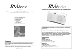
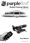
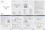
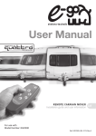
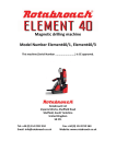
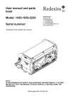
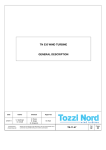
ELITE PRO Caravan Mover
User Manual
Model: ELITE PRO EM305
Part No: 042374
For Professional Installation Only
CAMEC ELITE PRO
EM305
Ref: ELITE PRO EM305-0814-Rev.A.
2
TABLE OF CONTENTS
Package contents (Parts list)
Introduction
Intended use
Specifications
Installation - safety guidelines
Installation - mechanical components
Installation - electrical/electronic components
Operation - safety guidelines
Operation - motor units
Operation - remote control handset
Operation - electronic control unit
Operation - getting started
Operation - hitching and unhitching
Maintenance
Trouble-shooting
Page
Page
Page
Page
Page
Page
Page
Page
Page
Page
Page
Page
Page
Page
Page
2
4
4
4
4
5
6
12
13
13
15
15
16
17
17
PACKAGE CONTENTS
Ref
Qte
Description
1
2
3
4
5
6
7
8
9
10
11
14
15
16
17
18
19
20
21
22
23
24
25
26
27
28
29
30
31
32
33
34
35
36
37
38
1
1
1
1
1
1
2
4
2
1
1
1
1
8
12
24
20
10
10
4
2
4
3
3
4
10
1
2
2
1
2
2
6
6
12
6
Motor unit (A)
Motor unit (B)
Main cross bar
Electronic control unit
Remote control handset with lanyard
Emergency key
Aluminium chassis clamp plates (set)
Bolt - M10x60
Chassis U plate
Instruction manual
Convoluted cable trunking
Positive (+) red battery cable 1.8m including fuse holder & 80A fuse
Negative (-) black battery cable 1.6m
Bolt - M10x50
Nylon nut M10
Washer 10mmØ
Screw - M4x15
Cable trunking P-clip 19.2mm
Cable P-clip 10.4mm
Battery terminal connector 8mmØ
Battery terminal connector 6mmØ
Spade fork connector big
Cable number markers (1,2,3,4)
Cable polarity markers (+,-)
Spade fork connector small
Cable tie 2x70
Battery isolation switch, cover & key
Roller distance spacer 20x20
Rubber isolation shell for battery isolation switch
Remote control handset wall holder
Screw – M5x40
Chassis Clamp Plates (Pair)
Bolt - M8x70
Nylon nut M8
Washer 8mmØ
Spring washer 8mmØ
CAMEC ELITE PRO
EM305
Ref: ELITE PRO EM305-0814-Rev.A.
3
Package Contents
Fig.1
376
37
35
2
34
36
666
166
38
6
34
1
B
3
A
4
5
MA
X
L
L
10
7
8
16
23
17
14
11
9
20
22
15
28
25
1
1
24
21
2
3
27
3
+ +
-
18
30
2
3
4
-
29
1
2
2
1
31
-
-
+
3
4
4
4
+
26
32
19
33
CAMEC ELITE PRO
EM305
Ref: ELITE PRO EM305-0814-Rev.A.
4
INTRODUCTION
Congratulations on choosing the Camec Elite Pro® EM305 caravan manoeuvring system. This has been
produced according to very high standards and has undergone careful quality control procedures.
By simply using the remote control handset you can move your caravan effortlessly into any position required
within operating guidelines. Soft start and soft stop technology allows you to manoeuvre your caravan
accurately without any shocks.
The caravan manoeuvring system consists of two 12V motor-power rollers, a 12V electronic control unit and a
remote control handset. To function, the motor-powered rollers must be engaged against the tyres of your
caravan. The Camec Elite Pro® EM305 Caravan manoeuvring system is provided with an automatic engaging
system. By pushing two buttons on the remote control, both motor-powered rollers will be simply press on the
tyre. Once this is done the manoeuvring system is ready for operation. The remote control will allow you to
move your caravan in any direction. You can even rotate the caravan on it’s own axis without moving forwards
or backwards.
Before proceeding with installation and starting to use the manoeuvring system, please
read this manual very carefully and be aware of the safety instructions! The owner of the
caravan will always be responsible for correct use. Keep this manual inside your caravan for
future reference.
INTENDED USE
The Camec Elite Pro® EM305 caravan manoeuvring system is suitable for single axle and double axle caravans.
Suitable only for L-profiled and U-profiled chassis with a chassis thickness between min. 2.8mm and max.
3.5mm.
Depending on the weight of the caravan, the manoeuvring system cannot overcome obstructions that are more
than about 2cm in height without assistance (please use wedges as a ramp).
The standard installation kit only provides parts for installing the caravan manoeuvring system within the
measurements given in Fig. 17.
SPECIFICATIONS
Designation
Operational voltage
Average current consumption
Maximum current consumption
Transmitting frequency remote control
Speed
Weight (2 motor set)
Permissible overall Weight single axle (2 motors)
Permissible overall Weight double axle (2 motors)
Permissible overall Weight double axle (4 motors)
Minimum width (caravan/trailer)
Maximum width (caravan/trailer)
Maximum tyre width
Power source (battery)
Camec Elite Pro® EM305
12 Volt DC
30 Ampere
120 Ampere
868MHz
approx. 11cm per sec.
approx. 33kg (exclusive battery)
2000kg (1750kg on 18% gradient)
2000kg (1750kg on 18% gradient)
3000kg (2350kg on 18% gradient)
1800mm
2500mm
205mm
LiFePO4: 12V, 20Ah (recommended Camec Elite
Pro® EM305) Lead acid: 12V, 80Ah (min.)
INSTALLATION - SAFETY GUIDELINES
Read this user manual carefully before installation and use. Failure to comply with these
rules could result in serious injury or damage to property.
These symbols identify important safety precautions. They mean CAUTION! WARNING!
SAFETY FIRST! IMPORTANT INFORMATION!
Before starting installation under the caravan:
Check the towing load of your vehicle and the gross weight of your caravan in order to establish whether they
are designed for the additional weight. The manoeuvring system itself has a weight of about 33kg and a battery
has a weight of about 20-25kg.
Check the minimal installation dimensions of the manoeuvring system based on figure 17.
CAMEC ELITE PRO
EM305
Ref: ELITE PRO EM305-0814-Rev.A.
5
Only use adapters and accessories that are supplied or recommended by the manufacturer.
Check that the caravan is disconnected from the battery supply and the mains electrical supply.
Check that the tyres are not worn and do have the same size and design (fitting to new or nearly new tyres is
the best option).
Make sure that the tyre-pressures are correct to the manufacturer’s recommendation.
Make sure the chassis is in good condition without any damage and is free from rust, dirt etc.
Stop work immediately if you are in doubt about the assembly or any procedures and consult one of our
engineers (Please refer to contact information on the last page of this manual).
Locate the battery isolation switch, it needs to be accessible at all times when parking and moving the
caravan.
Do not remove, change or alter any parts of the chassis, axle, suspension or brake mechanism. Any drilling of
holes in the chassis is not allowed.
Do not install the unit if you are under the influence of drugs, alcohol or medication that could impair your
ability to use the equipment safely.
INSTALLATION - MECHANICAL COMPONENTS
FOR PROFESSIONAL INSTALLATION ONLY. These instructions are for general guidance.
Installation procedures may vary depending on caravan type.
Working under a vehicle without appropriate support is extremely dangerous!
Please refer to figure 16 for an overview of the whole assembly fully fitted.
Place the caravan on a hard, level surface. The use of a lifting ramp or an assembly pit is ideal for access and
personal safety.
Unpack all of the components and check for the presence of all parts (see package contents list). Write down,
on the product warranty registration card, the 10-digit serial number (this is located on an aluminium plate on
the side of one of the motor units).
Clean the area of your chassis where you need to mount all components to ensure a good fitting.
Make sure the caravan is prepared for installation. Check before installation that important areas, such as
drains/spare tyre etc. do not cause any obstruction to the function of the caravan manoeuvring system.
Ensure both rollers are in the DISENGAGED position (Fig. 12), as the unit will not fit correctly otherwise (Note:
when fully disengaged, the pointer is positioned in the beginning of the yellow area).
Loosely assemble the left hand motor unit (1), right hand motor unit (2) and main cross bar (3) (Fig. 2). The
nuts (Fig. 2A), on the cross bar (3) to secure both motor units, must be no more than finger-tight at this stage.
Note: In principle, the unit should be fitted in front of the caravan road wheels, but if fitting in this position is
not possible because of obstacles or a too high hitch ball weight, it is permissible to fit it to the rear of the
wheels by rotating the whole assembly (Fig. 2) by 180° degrees.
Fit the Chassis Clamp Plates(34) to the chassis using bolts(35),nuts(36), washers(37) and spring washers(38), then
loosely fit the two aluminum clamp plates (7) to the plates (34) (Fig. 8 & 16) and attach. Use the bolts M10x60, nuts
M10 and washers M10 (8,17,18) and put them in the diagonal positioned holes of the aluminium chassis clamp
plates. Nuts must be no more than finger-tight.
Assemble the pre-mounted manoeuvring system on the aluminium chassis clamp plates by using the two Ushaped brackets (9), bolts M10x50, nuts M10 and washers M10 (16,17,18). Nuts must be no more than fingertight.
Make sure that aluminium drive rollers of the motors are approximately on the same altitude as the centre
(axle) of the caravan wheel (0mm~40mm, see Fig. 12). As well make sure that between the top of the motor
housing and the floor of the caravan is minimal 20mm space to make sure the motors can move freely (see Fig.
12 & 18). To compensate a possible unevenness (and lower the motors), Camec Elite Pro® has a set of
distance plates available. One set can compensate 15mm. In total three sets can be used so that an altitude of
45mm can be compensated.
Adequate ground clearance: Please notice that the min. distance between the lowest line of
motors and ground is 110mm, no matter what kinds chassis or install situation.
CAMEC ELITE PRO
EM305
Ref: ELITE PRO EM305-0814-Rev.A.
6
Make sure that the main cross bar (3) is positioned in the middle of the caravan (the centre of the bar is
marked).
With the main assembly is loosely fitted onto the chassis, slide the whole assembly along the chassis until the
rollers are 20mm away from the surface of the centre each tyre (Fig. 12). Two 20mm spacers (30) are provided.
It is vitally important that each roller is at exactly the same distance away from the tyre.
The whole assembly must be parallel to the caravan/trailer axle.
Slide the motor units in or out of the cross bar (3) accordingly to ensure the roller will have
the maximum possible contact with the tread of the tyre. Ensure that the position of each
motor unit does not obstruct shock absorbers (if fitted) and that the gear cover (Fig. 13) is
not too close to the surface of the tyre/shock absorber. The minimum clearance when the
drive units swivelled in is 10mm.
Re-check that there is sufficient space available (minimal 20mm) between the top of
the motor housing and the floor of the caravan so the motors can move freely (Fig. 18).
Fully tighten the four bolts (Fig. 2A) on the main cross bar (3) and lock them by the additional nuts.
Fully tighten all the nylon nuts on both clamping assemblies (Fig. 3). First tighten the diagonal placed M10x60
bolts with a 20Nm torque, and then M10x50 bolts to a 40Nm torque.
Re-check the distance of 20mm from the rollers to the tires, the position of the aluminium rollers in addition to
the surface of the tire and finally the distance between the gear cover (Fig. 13) and the tires & shock absorbers
(>10mm). The weight of the caravan must be on the wheels when doing this. If necessary, loosen the bolts and
re-adjust the position of the assembly.
Re-check that all bolts/nuts have been tightened to the correct torque!
The main mechanical components have now been installed.
INSTALLATION - ELECTRICAL/ELECTRONIC COMPONENTS
Make sure the 12V supply from the battery and any 230V electricity supply are disconnected.
Remove battery cable terminals and disconnect any external electrical power before starting work.
Find a suitable place for the electronic control unit (4), such as a storage area, under a seat or a bed. Make
sure this place is dry and close to the battery (40cm to 60cm). The electronic control unit can be mounted
vertically on a side wall or be mounted flat. When mounted vertically, the connections must point downwards to
avoid any short-circuits by objects falling into.
Fix the electronic control unit securely into position with two screws M5x40 (33). Note: if the provided screws
are not of suitable length or type for the desired location/material please substitute these as appropriate.
Drill a 25mm hole through the floor of the caravan approximately 150mm centrally in front of the control unit
(4) terminals.
Caution! Take extra care to avoid any chassis members, gas pipes and electrical wires!
Route and connect the motor-cables in accordance with wiring diagram (Fig. 15) (red = positive, black =
negative).
The wiring diagram (Fig. 15 + Table. A (see below)) depicts the wiring route when installing the motor units in
front of the wheels/axle towards the ‘A’ frame. Please refer to table B (below) for fitment of the motor units to
the rear of the axle.
Table. A
Table. B
FRONT OF AXLE FITTING
REAR OF AXLE FITTING
(4,6mm2 cables)
(4,6mm2 cables)
Motor unit A Positive (+) cable to terminal 4
Motor A Positive (+) cable to terminal 1
Motor unit A Negative (-) cable to terminal 3
Motor A Negative (-) cable to terminal 2
Motor unit B Positive (+) cable to terminal 2
Motor B Positive (+) cable to terminal 3
Motor unit B Negative (-) cable to terminal 1
Motor B Negative (-) cable to terminal 4
Automatic engaging system (1,5mm2 cables):
Motor unit A: Positive (+) cable to terminal d
Motor unit A: Negative (-) cable to terminal c
Motor unit B: Positive (+) cable to terminal b
Motor unit B: Negative (-) cable to terminal a
Automatic engaging system (1,5mm2 cables):
Motor unit A: Positive (+) cable to terminal b
Motor unit A: Negative (-) cable to terminal a
Motor unit B: Positive (+) cable to terminal d
Motor unit B: Negative (-) cable to terminal c
CAMEC ELITE PRO
EM305
Ref: ELITE PRO EM305-0814-Rev.A.
7
Mark the motor cables for both motor units using the cable markers (25). The cables for the left and the right
motor should have the same length. Avoid any loops.
Remember to leave a small amount of slack cable near the motors to allow for their movement when the drive
rollers are engaged.
Route all the cables along the underside of the caravan floor, inside the supplied convoluted trunking (11) (this
will protect the electrical cables against sharp edges and dirt) and through the drilled hole.
Secure the cable trunking (11) to the chassis or under body of the caravan by using the P-Clips (20) and screws
(19).
Once the all cables are through the drilled hole next to the control unit (4), cut the cables, ensuring that they
are the same length. Remove approx. 5mm of the insulation from the ends. Fix the big spade fork connectors
(24) to the motor cables and the small spade fork connectors (27) to the automatic-engaging-cables by using
crimping pliers. A secure and good quality connection on each cable is essential.
Attach the spade fork connectors to the terminals on the control unit (see wiring diagram Fig. 15) and fix them
tightly by the screws. A safe and good quality connection on each cable is again essential.
Find a suitable place for the battery power isolation switch (29) which includes an external holder with hinged
cover. Important: The switch must be mounted onto the exterior body of the caravan and be easily
accessible from the outside of the caravan in case of any emergency. The switch must be mounted close
to the location of the battery in order to keep the length of the battery cables to a minimum.
Use the cardboard template to position the hole positions and the drill holes. Mount the switch and the housing
with the bolts, washers and nuts, and finally mount it on the caravan with stainless steel screws (19).
Route the positive (+) power cable (including fuse) from the battery to the battery power isolation switch (29)
and than further to the control unit (4).
The electronic connections of the battery power isolation switch (29) must be covered by the supplied rubber
isolation shells (31).
Route the negative (-) power cable directly to the control unit (4).
No cables may be routed over the control unit!
Again it is recommended to use the supplied trunking (11) to protect the cables against sharp edges. Attach the
trunking with P-clips (20) and P-clip screws (19).
Cut the cables to an appropriate length and remove approx. 5mm of the insulation from the ends. Fix the
battery terminal connectors by using crimping pliers. Two types of battery terminal connector (22 & 23) are
provided for use as appropriate. A secure and good quality connection on each cable is essential.
Connect the battery cables (14 & 15) to the control unit (4): Attach the spade fork connectors to the positive
(+) en negative (-) terminal of the control box and fix them tightly by the screws.
Connect the battery cables to the existing battery terminals (red = positive, black = negative).
Caution! Make sure that you do not reverse the Positive (+) and Negative (-) connections.
Incorrect connection (reverse polarity) will result in damage to the control unit.
Seal the 25mm hole in vehicle under body using plastic body sealant.
Finally find a suitable place for the remote control handset wall holder (32) and fix this with the supplied
screws (out of reach of children or other unauthorised people).
Installation of the caravan manoeuvring system is now complete.
CAMEC ELITE PRO
EM305
Ref: ELITE PRO EM305-0814-Rev.A.
8
Parts Identification & Fitting Diagrams
Fig.2
A
A
Fig.3
A
A
Fig.4
B
B
H
C
D
E
A
R
G
C
I
I
J
J
MAX
E
F
L
D
F
L
M
L
N
K
Fig.6
Fig.5
A
A
Fig.6.1
Fig.7
B
A
CAMEC ELITE PRO
EM305
Ref: ELITE PRO EM305-0814-Rev.A.
9
Parts Identification & Fitting Diagrams
Fig.8
Fig.8.1
Fig.9
Fig.10
CAMEC ELITE PRO
EM305
Ref: ELITE PRO EM305-0814-Rev.A.
10
Parts Identification & Fitting Diagrams
Fig.12
20 mm
0~40 mm
Fig.11
A
B
Min.20 mm
Fig.11.1
C
Fig.14
B
C
D
A
Fig.13
10mm
|a|
b|
1
| 2
|
-
DC
12V
+
| 3
| 4
|c|
d|e
S
|
T
Fig.15
|a|
2
+
b|
1
b
a
+
-
| 2
|
-
DC
12V
+
| 3
| 4
|c|
d|e
+
|
1
-
Caravan
Front
B
CAMEC ELITE PRO
4
+
d
c
+
-
3
-
A
EM305
Ref: ELITE PRO EM305-0814-Rev.A.
11
Parts Identification & Fitting Diagrams
Fig.16
Fig.17
+
185mm (Min)
2.8mm to 3.5mm
30mm to 45mm
165mm (Min)
85mm (Min)
Fig.18
Min 20mm
1800mm to 2500mm (Max)
CAMEC ELITE PRO
EM305
Ref: ELITE PRO EM305-0814-Rev.A.
12
OPERATION - SAFETY GUIDELINES
Practice operating the manoeuvring system in an open area before using for the first time. This is to fully
familiarise yourself with the handset and manoeuvring system operation.
Before use, always check the caravan manoeuvring system for any damage.
When towing or moving the caravan please be aware, at all times, that ground clearance is reduced
when the manoeuvring system has been fitted.
Always ensure that children and pets are kept well out of the way during operation.
When operating the system, ensure that no hair, fingers or other body parts, clothing or any other
objects carried on the body can become trapped by moving or rotating parts (e.g. drive rollers).
In the event of malfunctions, pull on the handbrake immediately and turn off the main isolation power
switch.
To maintain signal strength, always make sure that, during manoeuvring, the distance between the
remote control and the caravan does not exceed 5 metres.
Due to the nature of a radio signal, it can get corrupted by external terrain or objects. So there may be
small areas around the caravan where the quality of reception reduces, hence the manoeuvring system
may stop momentarily.
Always be aware that the manoeuvring system increases the weight of your caravan or trailer. So this
reduces the payload of the caravan.
Do not exceed the total safe working load of 2000kg laden weight (caravan including load) when 2
motors are used and 3000kg laden weight (caravan including load) when 4 motors (twin axle) are used.
Always make sure that the rollers are fully disengaged from the tyres when the manoeuvring system is
not in use. This is better for the tyres and for the system.
Always make sure that the rollers are fully disengaged before towing/moving the caravan by vehicle or
manpower. This can damage the tyres, manoeuvring system and the towing vehicle.
Always make sure that after you have finished using the manoeuvring system, the battery power
isolation switch (29) is switched off and the key is removed and stored in a safe place (out of reach of
children or other unauthorised people). If you don’t switch off, the battery will be discharged by the
small ”standby” current.
Always make sure that the remote control handset is switched off and stored (in the wall holder) in a
safe place (out of reach of children or other unauthorised people). If you don’t switch off, the battery
will be discharged by the small ”standby” current.
Do not rely on the manoeuvring system to act as a brake.
Always apply the handbrake after manoeuvring, before disengaging the drive rollers from the tyres.
Do not use the manoeuvring system as a support when jacking up the caravan, as this can damage
the drive unit.
Depending on the weight of the caravan, the manoeuvring system cannot overcome all obstructions
without assistance. Please use wedges as a ramp.
All wheels and tyres on the caravan must be of the same size and design. If tyres are worn or new
tyres are fitted, the distance between the drive rollers and the tyres may need readjusting (see
“Installation - Mechanical Components”).
Sensitive objects such as cameras, DVD-Players etc. Must not be kept in the stowage box near the
control unit or the motor cable. They can be damaged by the electromagnetic fields.
Do not make any modifications on the caravan manoeuvring system (mechanical or electronically).
This can be very dangerous! No warranty claim will be accepted and we cannot guarantee the function
of the system if any modifications are made. We will not be liable for any damage whatsoever caused
as a result of incorrect installation, operation or modification.
13
OPERATION - MOTOR UNITS
The manoeuvring system has two motor units (1 & 2). In general they are mounted in front of the axle of the
caravan. Both units are identical but cannot be switched.
Fig. 3
A. Aluminium drive roller
B. Drive unit including 12V motor
C. Plastic motor cover
D. Base unit
E. Gear cover
F. Motor for automatic engaging system
Traction indicator label:
The yellow-green-red traction indicator label (Fig. 5A), on the side of each motor unit indicates if the roller is
depressing the tyre sufficiently to provide adequate traction.
•
If the pointer is in the yellow area – Rollers are not touching or depressing the tyre sufficiently.
•
If the pointer is in the green area – Rollers should be connecting correctly to the tyre (margin of 15mm).
•
If the pointer is in the red area – Rollers are connected to the tyre but in an extreme position. It could be
that the tyre of the caravan has insufficient air pressure or the drive unit has been knocked out of position
and a visit to a workshop is required to reposition the assembly.
Disconnect the motor powered rollers in case of emergency:
In the case that the caravan battery is discharged to far to automatically take of the motor powered rollers of
the tyre, or there is a defect, you can also do this manually. See figures 11 & 11.1.
Take the plastic cap (Fig. 11B) at the rear side of the housing of the motor for the automatic engaging system.
If necessary use a screwdriver. Place the emergency key (6) on the emergency socket in the motor unit (Fig.
11A & 11.1C) and turn it until the motor unit including motor powered rollers are in the beginning position.
Repeat this also on the motor unit on the other side.
Put the plastic caps back on the motor housing.
As soon as the battery is charged again, or the problem is solved, the motor powered rollers automatically work
again.
OPERATION - REMOTE CONTROL HANDSET
The remote control handset (5) is powered by one PP3 9Volt battery, and is activated by moving the slide
switch to “On”-I (Fig. 4A). Once activated the green LED (Fig. 4H) will illuminate and the directional controls
can now be used.
Fig. 4
A. Slide switch (“Off” –O and “On”-I)
B. Caravan forwards (both wheels rotate in forwards direction)
C. Caravan reverse (both wheels rotate in reverse direction)
D. Caravan left forwards (right wheel rotates in forwards direction)
E. Caravan right forwards (left wheel rotates in forwards direction)
F. Caravan left reverse (right wheel rotates in reverse direction)
G. Caravan right reverse (left wheel rotates in reverse direction)
H. Green LED: reflects status of the remote control and caravan manoeuvring system
I. Two handed service for automatic engaging of the motor powered rollers to the tyre
J. Two handed service for automatic disengaging of the motor powered rollers from the tyre
K. Blue LED: reflects status of the automatic engaging system
L. Red overload LED: Amp overload protection is activated. Wait about 60 seconds and try again
M. Blue 9V battery LED: The internal 9V battery of handset is near empty and needs to be replaced
N. Blue battery voltage LED: Caravan battery voltage too low or too high
When you drive straight forwards or reverse (press button B or C), it is also possible to adjust the direction by
additional pressing button D or E (when driving forwards) or button F or G (when driving reverse).
In addition, the ‘right forward’ (E) and ‘left reverse’ (F) buttons or ‘left forward’ (D) and ‘right reverse’ (G)
buttons may be pressed at the same time to turn the caravan around on its own axis without moving forward or
backward.
When you switch within 2 seconds from forward driving to reverse driving (and the other way around), a small
delay of 1 second will appear to protect the electronics and the motors.
CAMEC ELITE PRO
EM305
Ref: ELITE PRO EM305-0814-Rev.A.
14
The slide switch (Fig. 4A) also acts as an “Emergency stop”.
The automatic engaging system:
To activate the automatic engaging system of the motor powered rollers on the tyre, press the two buttons for
engaging (Fig. 4I) or disengaging (Fig. 4J) for at least three seconds. The blue LED (Fig. 4K) will blink fast
during these three seconds and every second there will be a beep. This warns you that the system will be
activated!
Engaging: After these three seconds the motor powered rollers will be pressed against the tyre, and the blue
LED will illuminate constant. Now you can release the two buttons. When the motor powered rollers are pressed
on the tyre strongly enough you hear a short beep, the blue LED will switch off and the system is ready to use.
Disengaging: after these three seconds the motor powered rollers will be released from the tyre, and the blue
LED will illuminate constant. Now you can release the two buttons. When the motor powered rollers are
completely disengaged you hear a short beep, the blue LED will switch off and is the caravan ready for transport
or use.
The remote hand set switches off:
•
After 3 minutes, if no button is pressed: After 2 minutes the buzzer will beep for 5 times with a repetition
after 3 minutes. Than the system switches in the “stand-by” modes.
•
After 6 minutes, if one of the movement buttons is permanently held down: After 5 minutes the buzzer will
beep for 5 times with a repetition after 6 minutes. Than the system switches in the “stand-by” modes.
The green LED goes off and the remote control handset is in the “stand-by” modes which means that there
always will be used some current which causes the battery to go down. So always make sure the remote
control handset is turned off by the slide switch.
To reactivate the remote control, move slide switch to “Off” –O and then back to “On”-I after approximately 1
second.
Error messages via the remote control handset:
Error messages of the Camec Elite Pro® EM305 will be communicated via the remote control handset by the
green LED (Fig. 4H), the error message LED’s (Fig. 4L, 4M & 4N) and a buzzer signal:
•
Green LED (Fig. 4H) off, no buzzer: remote control handset is turned off and also system is not activated
•
Green LED (Fig. 4H) continue on, no buzzer: remote control handset is turned on and system is activated
and ready to use.
•
Green LED (Fig. 4H) is blinking, no buzzer: no communication between handset and control unit. This could
be because of too much distance between remote control handset and control unit, or the battery isolation
switch for manoeuvring system is not turned on or that there is a distortion signal disturbing the
communication. As soon as connection is good again the green LED will be continue on and the system is
ready to use.
•
Blue battery voltage LED (Fig. 4N) is blinking in combination with buzzer (2 times blinking, break, 2 times
blinking, break etc.): Battery voltage too low (<10V). Battery needs to be recharged.
Blue battery voltage LED (Fig. 4N) is blinking in combination with buzzer (4 times blinking, break, 4 times
•
blinking, break etc.): Battery Voltage too high (over charged). Try to discharge the battery by turning on a
user (for example a lamp or water-pump).
Red overload LED (Fig. 4L) is blinking in combination with buzzer (6 times blinking, break, 6 times blinking,
•
break etc.): Amp overload protection is activated. Wait about 60 seconds and try again.
Blue 9V battery LED (Fig. 4M) is blinking, no buzzer: The internal 9V battery is near empty and needs to be
•
replaced.
Changing batteries in the remote control:
When the battery is empty (blue 9V battery LED (Fig. 4M) is blinking), it needs to be replaced.
•
Open the rear cover of the handset (Fig. 6A).
•
Take out the dead/old battery and dispose in the appropriate way.
•
Install a new replacement battery (Fig. 6.1). Make sure to use a leak proof PP3 (9Volt) battery (No claims
under guarantee can be considered for damage caused by leaking batteries).
•
Close the rear cover again.
Dead and used batteries may leak and damage the remote control handset! Remove the batteries if the
handset is not going to be used for an extended period.
CAMEC ELITE PRO
EM305
Ref: ELITE PRO EM305-0814-Rev.A.
15
OPERATION - ELECTRONIC CONTROL UNIT
The electronic control unit (4), which is mounted inside your caravan, is responsible for controlling the
manoeuvring system.
The control unit has three LED’s, one pushbutton and one slide switch (Fig. 14):
Green LED (Fig. 14B): Power LED continuously illuminated when system is activated (by moving slide switch
to “On”-I). If the handset far away from the control unit, beyond the availably distance, this LED will go out.
Blue LED (Fig. 14C): Error message LED concerning caravan battery:
•
Blue LED is blinking (2 times blinking, break, 2 times blinking, break etc.): Battery voltage too low (<10V).
Battery needs to be recharged.
•
Blue LED is blinking (4 times blinking, break, 4 times blinking, break etc.): Battery Voltage too high (over
charged). Try to discharge the battery by turning on a user (for example a lamp or water-pump).
Red LED (Fig. 14D) is blinking (6 times blinking, break, 6 times blinking, break etc.): Amp overload protection
is activated. Wait about 60 seconds and try again.
In general all error messages will reset automatically after one minute. If this is not the case, reset the
electronics of the manoeuvring system by switching off the system via the isolation switch and the remote
control handset for at least 15 seconds and then turning it on again.
The Reset Button (Fig. 14A): The remote control handset and the control unit are synchronised with each
other in the factory. If the control unit or the remote control handset is replaced, they must be re-synchronised
as described below:
•
•
•
•
•
•
Check the installation in accordance with the installation instructions and ensure that the drive rollers are
not applied. Check that the battery is properly connected, check the condition of the battery and that a
voltage of 12 V is present at the control unit.
Please ensure that the battery isolation switch is on.
Activate the remote control handset by sliding the slide switch to “On”-I (Fig. 4A). The green LED on the
remote control handset (Fig. 4H) starts to flash slowly.
Press the reset button (Fig. 4A) on the control unit. All three LED’s on the control unit (Fig. 3B, 3C & 3D)
will flash slowly.
Press both forwards (Fig. 4B) and reverse (Fig. 4C) button on the remote control handset for about 3
seconds. Then the handset buzzer will give a short beep to confirm that the synchronisation is complete.
After successful synchronisation, the green LED on the control unit (Fig. 4B) and on the remote control
handset (Fig. 4H) will illuminate continuously.
The single-twin axle function switch (Fig. 14S/T): The Camec Elite Pro® EM305 Caravan manoeuvring
system is suitable for both single axle and twin axle caravans. You just need to move the single-twin axle
function switch (Fig 14S/T) on the control unit, so that the manoeuvring system can be used for a singleaxle caravan or a twin-axle caravan (for 2 motor use but also for 4 motor use). In the twin axle function
the all wheels will drive but at a different speed.
The switch standard pre-selected for single axle use (Fig 14S). For twin axle use, just move the switch to the
twin axle position (Fig. 14T). When move the single-twin axle function switch, the battery power isolation
switch (29) must be turned off.
OPERATION - GETTING STARTED
Please make sure you read the safety instructions very carefully and make sure that you
follow these guidelines!
Make sure that the battery that supplies the system is fully charged and in good condition.
Make sure that the caravan is free from the vehicle and the handbrake is on. Also make sure
that the corner steady feet are fully raised.
Turn on the battery power isolation switch (29).
Activate the manoeuvring system by move slide switch to “On”-I on the remote control (Fig. 4A). The green
LED (Fig. 4H) on the remote control handset will illuminate and you will hear a short beep. The remote control
is ready for use.
To activate the system press the two (Fig. 4I) buttons for three seconds. The blue LED (Fig. 4H) will blink fast
during these three seconds and every second there will be a beep. This warns you that the system will be
activated!
CAMEC ELITE PRO
Before operating the manoeuvring system, release the handbrake.
EM305
Ref: ELITE PRO EM305-0814-Rev.A.
16
After these three seconds the motor powered rollers will be pressed against the tyre and the blue LED will
illuminate constantly. Now you can release the two buttons. When the motor powered rollers are pressed on
the tyre strongly enough, the blue LED will switch off and is the system ready to manoeuvre. The colour of the
traction indicator label (Fig. 5A) should be in the green area.
Now you can choose the movements according the symbols shown on the remote control. Straight forward (Fig.
5B), straight reverse (Fig. 4C), left forward (Fig. 4D), left reverse (Fig. 4F), right forward (Fig. 4E), right
reverse (Fig. 4G).
In addition, the left forward (Fig. 4D) and right reverse (Fig. 4G) buttons or right forward (Fig. 4E) and left
reverse (Fig. 4F) buttons may be pressed at the same time to turn the caravan around on its own axis without
moving forward or backward.
When you drive forwards or reverse (press button 4B or 4C), it is also possible to adjust the direction by
additional pressing button 5D or 5E (when driving forwards) or button 4F or 4G (when driving reverse).
Because of the “soft start” technology, the caravan will slowly speed up. Because of the “soft stop” technology,
the caravan will stop slowly. This allows you to manoeuvre your caravan even more accurately without any
shocks.
WARNING: When the buttons on the remote control handset are released, the caravan will
slowly stop after 0.5 second and continue to move about 6cm (depending on final speed).
When the buttons of the remote control handset are released when the system is still in the
“soft start” stage (slowly speed up), the caravan will stop immediately.
After the “soft start” stage the caravan moves according one fixed speed. The speed can increase a little when
going downhill and decrease a little when going uphill. TIP: The manoeuvring system is more efficient when
reversing the caravan up an incline.
When the caravan is in position, you need to secure the handbrake. To deactivate the system,
press the two buttons (4J) for three seconds.
Press at the same time, during at least three seconds, the two buttons for disengaging the motor powered
rollers (Fig. 4J). The blue LED (Fig. 4H) will blink fast during these three seconds and every second there will be
a beep. This warns you that the system will be activated!
After these three seconds the motor powered rollers will be released from the tyre and the blue LED will
illuminate constantly, now you can release the two buttons. When the motor powered rollers are
completely disengaged the blue LED will switch off and the system is ready for transport.
After manoeuvring, deactivate the manoeuvring system by moving the slide switch to “Off”-O on the remote
control handset (Fig. 4A). The green LED (Fig. 4H) on the remote control handset will turn off. Store remote
control in a safe place (out of reach of children or other unauthorised people).
Turn off the battery power isolation switch.
Before you start driving always make sure that the both drive units are fully disengaged!
OPERATION - HITCHING AND UNHITCHING
It is possible to position the caravan’s hitch exactly over a stationery car’s tow ball using the manoeuvring
system. But please be very careful!
Use the button controls on the remote control to bring the hitch of the caravan to the car. The soft start
technology allows you to locate the tow-ball of the car by centimetre. It is better reach the tow ball with several
short “trips” rather than trying to do it in one “trip”.
WARNING: When the buttons on the remote control handset are released, the caravan will
slowly stop after 0.5 second and continue to move about 6cm (depending on final speed).
When the buttons of the remote control handset are released when the system is still in the
“soft start” stage (slowly speed up), the caravan will stop immediately.
When the hitch is right above the tow ball of the vehicle, lower the hitch to the ball and engage in the normal
way using the jockey wheel.
Release the rollers from the caravan’s tyres. You cannot tow the caravan with the drive
units are engaged! Before you start driving always make sure that the both drive units are
fully disengaged!
Trying to drive away with the drive units still engaged, will damage the manoeuvring system,
your caravan tyres and strain your tow vehicle!
CAMEC ELITE PRO
EM305
Ref: ELITE PRO EM305-0814-Rev.A.
17
MAINTENANCE
To prevent the battery from becoming totally discharged during long periods of inactivity it must be
disconnected, fully charged and frost-proof stored.
Please check regularly that the rollers of the drive units are free of any dirt, or debris that may have been
picked up from the road.
Regularly clean the drive units with a water hose to dissolve mud etc.
Please check regularly the distance between the rollers and the tyres. In the neutral (fully disengaged) position
this must be about 20mm.
Once a year have your caravan manoeuvring system maintained and visually inspected. This inspection must
include all the bolt/nut connections, the cables and electrical connections and lubrication of movable
parts/joints.
In case of any failure or problem, please contact your Camec Elite Pro® supplier.
TROUBLE SHOOTING
Should your manoeuvring system fail to operate, please check the following:
Unit fails to operate, does not function at all:
Make sure that the battery power isolation switch (29) is turned on.
Check the cable-connection between the caravan battery and the control unit.
Check the fuse (80A) in the red positive battery cable (Fig. 7). If the fuse is blown, it must be replaced with a
fuse of the same value (80A). Never “bridge” the fuse (if needed contact your Camec Elite Pro® supplier). To
replace the fuse, first disconnect the positive (+) power cable from the battery. Than release the mounting
screws that hold the fuse (Fig. 7A), replace the fuse (Fig. 7B), and finally tighten the screws securely. Close the
housing of the fuse and connect the positive (+) power cable again to the battery. The system is ready again
for use.
Check the battery of the remote control handset. If empty, renew the 9V battery.
Caravan battery could be empty. If empty, recharge completely or renew caravan battery before taking any
further action.
Caravan battery could be overloaded. Check your charging equipment and try to discharge the battery by
connecting/using a light or any other load. If this does not give any result, renew caravan battery before taking
any further action.
Check the distance between the remote control and the caravan is not more than 5 metres. If there is no signal
between the remote control handset and the control unit, the manoeuvring system will not function at all and
the green LED on handset is blinking.
Check if there is any distortion signal (other transmitter, high power cables, Wifi etc.) that disturbs a good
communication between remote control handset and control unit. If there is no good communication between
the control unit and remote control handset, the manoeuvring system will not function and the green LED on
remote control handset is blinking.
In general, all error messages will reset automatically after one minute. If this is not the case, reset the
electronics of the manoeuvring system by switching off the manoeuvring system via the isolation switch and the
remote control handset for at least 15 seconds and then turn them on again.
Unit fails to operate or moves intermittently:
Check the battery of the remote control. If empty, renew the 9V battery.
Caravan battery could be empty. If empty, recharge completely or renew caravan battery before taking any
further action.
Caravan battery could be low - with the rollers engaged. Check the voltage drop on the caravan battery, if this
drops well below 10 volts, charge or renew caravan battery
Caravan battery could be overloaded. Check your charging equipment and try to discharge the battery by
connecting/using a light or other load. If this does not give any result, renew caravan battery before taking any
further action.
Check the cable-connection between the caravan battery and the control unit.
CAMEC ELITE PRO
EM305
Ref: ELITE PRO EM305-0814-Rev.A.
18
Badly connected or corroded battery terminals can cause intermittent problems, check battery terminals, clean
and connect again.
Check the distance between the remote control and the caravan is not more than 5metres. If there is no signal
between the remote control handset and the control unit, the manoeuvring system will not function at all and
the green LED on handset is blinking.
Check if there is any distortion signal (other transmitter, high power cables, Wifi etc.) that disturbs a good
communication between remote control handset and control unit. If there is no good communication between
the control unit and remote control handset, the manoeuvring system will not function and the green LED on
remote control handset is blinking.
In general, all error messages will reset automatically after one minute. If this is not the case, reset the
electronics of the manoeuvring system by switching off the manoeuvring system via the isolation switch and the
remote control handset for at least 15 seconds and then turn them on again.
Roller will not turn, spindle rotates freely:
The motor or gear is broken, please contact your Camec Elite Pro® supplier.
In case of any doubt, please call your Camec Elite Pro® supplier.
CAMEC ELITE PRO
EM305
Ref: ELITE PRO EM305-0814-Rev.A.
Contact Information
Australia
47-63 Remington Drive
Dandenong South 3175
Phone: 1300 4 CAMEC (22632)
www.camec.com
New Zealand
Airport Business Centre
44 Montgomerie Road, Mangere
Phone: 0011 64 9 257 2419