1
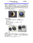
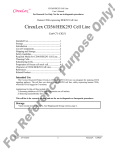
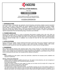
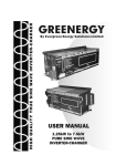
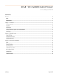
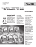
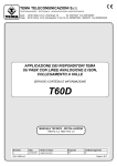
SolarNAPL
TR-51600
Operator’s
Manual
Version 1.2
Durham Geo Slope Indicator
2175 West Park Court
Stone Mountain, GA 30087
USA
Phone: 800-837-0864 or +1.770.465.7557
Fax: 770.465.7447
e-mail: [email protected]
www.DurhamGeo.com
Table of Contents
APPLICATION, OPERATION AND MAINTENANCE GUIDE INTRODUCTION
ABOUT THE SOLARREM PRODUCT FAMILY.............................................1
INSPECTION....................................................................................................1
Unit Protection ..............................................................................................2
Storage .........................................................................................................2
SPECIFICATIONS ...........................................................................................2
Performance Specifications.........................................................................2
TECHNICAL SUPPORT ..................................................................................4
Returning Merchandise for Service.............................................................4
For Resellers Only:.......................................................................................4
Trademarks ..................................................................................................4
Disclaimer .....................................................................................................4
ABOUT THE SOLARREM ...............................................................................5
TECHNICAL DESCRIPTION – OVERVIEW ..................................................5
ABOUT THE COMPONENTS .........................................................................6
EXTERNAL COMPONENTS...........................................................................6
INTERNAL COMPONENTS ............................................................................6
GENERAL SAFETY INFORMATION..............................................................8
INSTALLATION INSTRUCTIONS...................................................................9
HOW TO INSTALL OUR PRODUCTS RIGHT...THE FIRST TIME...............9
What’s the first thing I should do? ...............................................................9
Pole Installation and Mounting ....................................................................9
Electrical Wiring............................................................................................9
FREQUENTLY ASKED QUESTIONS ..........................................................10
2
1
INITIAL SET-UP OF THE SOLARNAPL.......................................................12
INTRODUCTION TO SETUP ........................................................................12
OPERATING THE SOLARREM....................................................................12
Starting Setup.............................................................................................12
The Components of the SolarREM unit are as follows: ...........................12
Setup Keys on the Optimate PLC Controller............................................14
Operation of the OptiMate PLC Controller................................................14
SYSTEM OPERATION ..................................................................................15
Start Up Screen..........................................................................................15
Air Discharge Set-Up Procedure...............................................................16
Checking System Operations....................................................................16
MAINTAINING THE SOLARREM .................................................................17
SYSTEM CHECKOUT ...................................................................................17
MAINTENANCE .............................................................................................17
Maintenance Procedures...........................................................................17
Glossary:.....................................................................................................23
3
Chapter
1
Application, Operation and Maintenance
Guide Introduction
SolarREM – The First Truly Environmental Remediation Product
About the SolarREM Product Family
SolarREM identifies the three provided for assistance in bioremediation of contaminated
sites, remote from an economical power supply, not quickly accessible, and subject to
long term remediation requirements.
1) The SolarDRIP provides fluid injection to the ground water table.
2) The SolarVENT provides low air flow to the ground for bioremediation of LNAPL
contaminants.
3) The SolarNAPL provides pneumatic pumping capabilities for removal of LNAPL
contaminants laying on the ground water table. It is provided with a storage tank level
sensor to shut the system down when full to prevent a surface spill.
4) The SolarPurge provides pneumatic pumping capabilities for low flow groundwater
pumping.
5) The SolarSPARGE provides higher air flow into the ground water table to promote
bioremediation and volatilization of LNAPL contaminants in the groundwater.
6) The SolarSKIM provides surface oil skimming equipment for removal of LNAPL
contaminants from surface waters.
Inspection
Upon receipt of shipment at the job site, carefully check the shipment against the bill of
lading. Make sure all units have been received. Inspect the carton or crating of each unit
and inspect each unit for damage. Repackage unit after verifying that all components are
included. Assure that the carrier makes proper notation of any shortages or damage on all
copies of the freight bill and that he completes a Carrier Inspection Report. Concealed
damage not discovered during unloading must be reported to the carrier within 15 days of
receipt of shipment. NOTE: It is the responsibility of the purchaser to file all necessary
claims with the carrier. Notify the SolarREM Traffic Department of all damage within fifteen
(15) days of shipment.
Unit Protection
Cover units on the job site with either shipping cartons, vinyl film, or an equivalent
protective covering. Cap the open ends of pipes stored on the job site. In areas where
painting, plastering, or the spraying of fireproof material has not been completed, all due
precautions must be taken to avoid physical damage to the units and contamination by
foreign material. Physical damage and contamination may prevent proper start-up and
may result in costly equipment clean-up. Examine all pipes, fittings, and valves before
installing any of the system components. Remove any dirt found on these components.
Storage
CAUTION
Do not store or install units in corrosive environments. Corrosive conditions and high
temperature or humidity can significantly reduce performance, reliability and service life.
Always move units in an upright position. Tilting units on their sides, or back may cause
equipment damage.
Upon the arrival of equipment at the job site, immediately store solar panel units in their
shipping cartons in a clean, dry area. Store units in an upright position at all times.
Specifications
The SolarREM units are designed to provide operating capabilities in remote locations
away from the power grid, and to be operated in a simple fashion, both in setup and in
operating mode. The units are designed for a no shock or explosion hazard environment.
A deep cycle battery is provided to withstand the rigors of weather and deep power draw.
The solar panel provides recharge of the battery to permit a longer operating period of the
units.
A low draw DC powered compressor pump provides the necessary compressed air for all
configurations.
The control center of the SolarREM units is a PLC unit and operator interface panel.
This permits factory default settings, or modifications to the cycle by the onsite
operator to provide a site specific cycle time for optimum product removal.
Performance Specifications
The Standard Base Model as supplied by SolarREM is designed to provide a sturdy low
maintenance air compressor providing programmable timing to maximize the on/off cycle
to the conditions of the site. The controller interface is located inside the steel box to
provide access only by authorized personnel. Access to total cycles and air compressor
on time information is provided to aid in reporting of equipment performance.
2
The battery and solar panel are sized to maximize operating time, providing up to 2 days
operations during periods with minimal sunlight (heavy rain). The solar panel ensures
quick recharge to get the battery back into operation as the result of a long low sunlight
period.
A 7.5 gallon ASME air receiver tank is standard to provide optimum compressor pump
operation and minimize on off cycles that result in large battery draw.
The table on the following page summarizes the SolarREM family of equipment and
typical performance limits for standard operations.
No.
Application
Model
Type
Wells
Performance
gpd
1
SolarDrip
DB020
Basic
1
30
fluid injection
DM060
Programmable
3
60
cfd
2
SolarVent
BB060
Basic
1
200
pulsed air, low flow
BP060
Programmable
1
200
bioventing
BP120
Programmable
1
400
depth/psi
30/30
60/40
90/70
gpd
3
SolarNAPL
NB020
Basic
direct free product
NP060
Programmable
1
recovery
NP120
Programmable
1
NM060
Programmable
2
60
NM120
Programmable
4
120
1
30
22
15
60
50
40
120
100
80
50
40
100
80
gpd
4
SolarPurge
PB020
Basic
1
30
22
15
low flow
PP060
Programmable
1
60
50
40
groundwater
PP120
Programmable
1
120
100
80
pumping
PM060
Programmable
2
60
50
40
PM120
Programmable
4
120
100
80
water column/psi
10/5
20/10
30/15
cfd
5
SolarSparge
SB060
Basic
1
220
160
100
pulsed air sparging
SP060
Programmable
1
220
160
100
SP120
Programmable
1
440
320
200
gpd
6
SolarSkim
MB020
Basic
1
30
surface oil
MM060
Programmable
2
60
skimming
MM120
Programmable
4
120
The performance rates indicated above assumes six hours of sunlight, the units and pumps are installed
in accordance with the Manufacturer's Guidelines, and the soil environment can yield the indicated rates.
3
Technical Support
Information presented in this publication has been carefully checked for reliability.
However, no responsibility is assumed for inaccuracies. The information contained in this
document is subject to change without notice.
If a problem arises with your system, you should turn to your dealer or the manufacturer
for help first. Your system has most likely been configured by them, and they should have
the best idea of what hardware and software your system contains. Hence, they should be
of the most assistance. Further, if you purchased your system from a dealer near to you,
you can actually bring your system in to them to have it serviced, instead of attempting to
do so yourself (which can have expensive consequences).
Manufacturer
DURHAM GEO SLOPE INDICATOR
2175 West Park Ct
Stone Mountain, Ga 30087, USA
Tel: +1-770-465-7557
Fax: +1-770-465-7447
Returning Merchandise for Service
During the warranty period, contact your distributor or system vendor FIRST for any
product problems. This warranty only covers normal customer use and does not cover
damages incurred during shipping or failure due to the alteration, misuse, abuse, or
improper maintenance of products.
For Resellers Only:
A receipt or copy of your invoice marked with the date of purchase is required before any
warranty service can be rendered. You can obtain service by calling the manufacturer for
a Return Merchandise Authorization (RMA) number. The RMA number should be
prominently displayed on the outside of the shipping carton and the package should be
mailed prepaid, or hand-carried to the manufacturer. SolarREM will pay to have the unit
shipped back to you.
Trademarks
SolarREM is a trademark of the SolarREM Corporation.
All other trademarks are the property of their respective companies.
Disclaimer
Information presented in this publication has been carefully checked for reliability.
However, no responsibility is assumed for inaccuracies. The information contained in this
document is subject to change without notice.
4
Chapter
2
About the SolarREM
The SolarREM is a solar powered remediation unit capable of either free product recovery
system (SolarNAPL, SolarPURGE, SolarSKIM), fluid injection (SolarDRIP) or pressurized
air (SolarVent, SolarSPARGE). The unit is capable of running up to 2 days without
sunlight. By relying on solar power, SolarNAPL can be installed in any location where a
power supply necessary to run traditional pumping systems is not economically available.
SolarNAPL is a self-contained remediation system consisting of a solar panel, battery, air
compressor and pump and associated wiring and controls. The solar panel charges the
battery, which serves as the power supply for the air compressor and the system controls.
When activated, the compressed air is discharged to the pneumatic pump, forcing the
product up the pump discharge hose and into a holding tank. The operating
characteristics and performance of the SolarNAPL is determined in part by the
specifications of the solar panel, battery and pump. Operating parameters such as the
cycle time is by a programmable logic controller (PLC). The PLC is also programmed to
record system performance data.
To operate correctly and efficiently, air must be pumped into the pneumatic pump at a
pressure sufficient to displace the water column and overcome frictional losses in the
system. The injected air displaces the product collected in the pump and discharges it to
the collection system. This air and product cycling continues in the pump while the air is
available.
Technical Description – Overview
The power supply for SolarNAPL consists of a photo-voltaic array and battery. The
photovoltaic cells use sunlight to charge the battery. The battery in turn powers the
system controls and, the air compressor pump. The pump fills an air receiver tank that
provides the pressure and volume of air required to displace the product in the pneumatic
pump.
A voltage regulator is used to prevent the battery from overcharging. The voltage
regulator also prevents draining of the battery when there is not enough sunlight (e.g., at
night) to sustain flow of electricity from the solar panel to the battery.
The SolarNAPL is operated by a programmable logic controller (PLC). After an on-site
pilot test to determine optimum operating conditions including injection pressure and air
flow rate, the PLC is programmed through the controller interface for on and off cycles.
When the system is activated, the compressor pump pressurizes the air receiver tank.
When the pressure inside the tank drops below the lower set value, the pump turns on to
re-pressurize the tank until the air pressure reaches the high set value. At the set
intervals, the solenoid valve opens and allows the flow of air to the pneumatic pump.
5
Chapter
3
About the Components
External Components
1) Solar Panel:
The solar panel is capable of producing a minimum of 16 to 20 amphours per day at 75 percent sunlight for a minimum of six hours.. A minimum
configuration is a 60 Watt panel, with larger panels used as necessary for particular
sites or applications.
2) Battery: The battery supplies 12-volt DC power to the unit. It is capable of providing
back up power for up to two days for a typical SolarREM installation. The battery is an
industrial 12-volt deep cycle battery designed for use with solar panels. The minimum
size provides 120 amp-hours. The battery is an absorbed glass mat (AGM)
construction . We do not recommend use of typical lead acid batteries.
3) Weatherproof Enclosure: The weatherproof enclosure is designed to house and
protect all equipment except the solar panel and the air receiver tank. The enclosure
provides weather protection as well as vandalism protection of less durable
equipment. The weatherproof enclosure is enamel-coated steel for long wear.
Dimensions are 20 inches high by 16 inches wide by 6 inches deep, with a front
opening, locking panel.
4) Air Receiver Tank: The air receiver tank equalizes air flow and eliminates pulsing of
flow from the air compressor to the well point. The air receiver tank is a 7.5 gallon
tank meeting the ASME regulations.
5) Mounting Track and Mounting Rail: The SolarSPARGE system, including the solar
panel, weatherproof enclosure and air receiver tank are mounted on Schedule 40
galvanized steel piping, or Unistrut assemblies.
Internal Components
1) Photovoltaic Charge Controller: Also known as a charge regulator, this part of the
system provides safe charging of the battery by the solar panel, and regulates the
charge flow to maximize the operating life of the battery. The charge regulator also
prevents discharge of the battery back through the solar panel during periods of no
sunlight. The charge regulator shall be a Prostar 30, manufactured by Morningstar
Corporation, equipped with a link to a computer through an RS232 port.
6
2) Control Panel and Programmable Logic Controller (PLC): The control panel and
PLC control and automate the various functions of each piece of equipment. The
PLC includes ports for computer or telephone connections to monitor system
operation and performance. The control panel shall be manufactured with the DL105
PLC made by Direct Logic. The unit shall include 10 inputs and 8 outputs for system
monitoring and response.
3) Solenoid Valve: The solenoid valve is the open/close control point for air supply to
the well point. The solenoid valve is controlled by the PLC and is placed in line after
the air receiver tank. The solenoid valve shall be an ASCO Red Hat two-way solenoid
valve.
4) Pressure Switches: The high pressure switch shall have a range of 80-100 psi and
be equipped with a dual manual lever (Automatic-Off). The low pressure unit shall
have a range of 0 to 40 psi and operate on an automatic setting. The pressure
switches shall be supplied by Pumptrol, Grainger, or the equivalent.
5) Air Compressor Pump: The air compressor shall be one of two options, depending
on site conditions or user specifications. A Gast oil-free rocking piston pump (Model
75R645) is capable of producing a maximum pressure of 30 psi at 4.9 cfm open flow.
The alternative, a Gast twin cylinder pump (Model 6L) can produce a maximum
pressure of 50 psi at 6.2 cfm, and can be used where either higher pressure or air
flow or both are required.
6) Piping: All internal piping shall be high-pressure flexible hosing with Schedule 40
galvanized steel pipe external fittings and external screw threads. All fittings shall be
clamped or coated with Teflon tape to minimize air loss.
7
Chapter
4
General Safety Information
The SolarREM Equipment is designed to be safe when handled correctly. It is important
that all site safety procedures be followed, including all Occupational Heath and Safety
Administration (OSHA) site requirements.
Whenever working around any electrical equipment, care must be taken to avoid shock or
worse injury.
The solar panel cells are encapsulated between a tempered glass cover and an EVA
pottant, with PVF back sheet to provide maximum protection from the most severe
environmental conditions. The entire laminate is installed in an anodized aluminum frame
to provide structural strength and ease of installation.
8
Chapter
5
Installation Instructions
How to install our products right...the first time.
What’s the first thing I should do?
The first thing you should do is read this user’s manual. It contains important information
which will make configuration and setup much easier.
Pole Installation and Mounting
The next step is to properly attach the SolarREM unit and equipment to a secure mounting
pole. We recommend a three inch Schedule 40 steel pole mounted a minimum of four
feet into the ground with a concrete base of a least one foot around. The pole should
extend about seven feet high to allow for clearance of the solar panel from the box.
Electrical Wiring
Once the SolarREM unit, solar panel(s) and battery have been installed as per the
installation configuration, all components must be electrically connected, and grounded.
WARNING! To avoid possible injury or death due to electrical shock, carefully examine
the wiring, and connect to the appropriate battery and solar panel lead. The solar
controller will prevent cross connections from damaging the solarREM unit.
CAUTION! Use only copper conductors for field installed electrical wiring. All field
installed wiring, including electrical ground, must comply with the National Electrical Code
(NEC) as well as all applicable local codes. In addition, all field wiring must conform to
Class II temperature limitations described in the NEC. Consult the unit wiring diagram
located on the inside of the compressor access panel to ensure proper electrical hookup.
Once the solarREM unit is mounted on the platform provided by you, remove the four 10
Gauge wires from the packaging on the back of the control panel box.
The wires are labeled for the Battery and for the Solar Panel. Green is for positive, and
Black is for the negative. Connect each of the wires to the appropriate terminals on the
battery and solar panel, ensuring a tight connection is made.
9
Once this is completed, open the control box, front panel and familiarize yourself with each
of the components. Your will note that power should now be on at the Solar Controller,
PLC and Controller Panel.
Once the SolarREM unit is mounted and electrically connected, check that the solar
controller is signaling a battery charge, and the solar panel is charging the battery. If all
lights are operating, you are ready for the initial setup of the operating parameters. Refer
to the next section for details on running the SolarREM unit.
Frequently Asked Questions
Q: Why don’t I get a display after I connect the wiring.
A: Check for cross connections with the wiring. If you have inadvertently connected either
the battery or the solar panel to the wrong leads, you will not get a signal on the solar
controller. If the wiring is crossed, the same will apply, you will not get a signal.
Q: Why don’t I get an indication the solar panel is charging the battery?
A: First check the solar panel is connected to the solar controller, and with the correct
polarity. Second, check the solar panel is pointed at the correct angle and location to
receive the maximum sunlight during the day.
Q: What is a solar cell.
A: A solar cell is a kind of semiconductor device that takes advantage of the photo-voltaic
effect, in which electricity is produced when the semiconductor's PN junction is irradiated.
When light strikes a solar cell, part of it is reflected, part of it is absorbed, and part of it
passes through the cell. The absorbed light excites the bound electrons into a higher
energy state, making them free electrons. These free electrons move about in all
directions within the crystal, leaving holes where the electrons used to be, and the holes
also shift around the crystal. The electrons (-) collect in the N-layer, the holes (+) in the Player. When the outside circuit is closed, electricity flows.
Q: What about grounding of the SolarREM unit
10
A: The SolarREM unit is to be grounded to the mounting pole with the provided ground
wire.
11
Chapter
6
Initial Set-up of the SolarNAPL
Introduction to Setup
This manual describes the SolarREM Setup program. The setup program lets you modify
the basic system configuration settings. The settings are then stored in a dedicated
battery-backed memory, called CMOS RAM, that retains the information when the power
is turned off.
The processor in your SolarREM unit is a customized version of an industry-standard
programmable logic controller (PLC). The PLC provides critical low-level support for the
system central processing, memory, and I/O subsystems.
The PLC has been customized by adding important, but nonstandard, features such as
password protection, power management, and detailed fine-tuning of the chipset
controlling the system. The rest of this manual is intended to guide you through the
process of configuring your system using the controller interface.
Operating the SolarREM
Starting Setup
The Components of the SolarREM unit are as follows:
1) Solar Controller: Controls and monitors recharge of the battery, as well as the on/off
power supply to the unit.
2) PLC: Provides the functionality of the unit to allow operations to site conditions.
3) PLC Controller: Provides the operator interface to change the operating parameters,
as well as determine the system operating duration.
4) Regulator and Pressure Gauge: Provides the regulation point for system discharge
pressure, and can be adjusted to suit site specific requirements.
12
Once the SolarREM unit is installed and connected to the solar panel and battery, power
will be on through the system. The SolarREM PLC is immediately activated when you first
connect the battery power. The PLC starts a countdown to system activation based on the
default settings in the EPROM. The system automatically starts at the end of a five minute
countdown, or alternatively by pressing the F1 or START button.
You will note on the ProStar 20 Photovoltaic (Solar) Controller, that a green light will be on
indicating the battery type as SEALED. Your are shipped with a Solar Extender Advanced
Glass Matte (AGM) type battery. This is a sealed type battery, and is the recommended
battery for this unit. However, for optimum operation of this battery, select as a flooded
battery. Follow the instructions on the Solar Controller to change the battery type (touch
battery negative to terminal on solar controller with connecting wire to turn light off).
Ensure the air receiver tank bottom drain plug is fully closed (clockwise). Pull down on the
air regulator knob to engage it. Then turn the regulator counter-clockwise to remove all
discharge line pressure. Depress the red selector switch on the pressure sensor
(Pumptrol) down, or towards the pump, to the automatic position. You are now ready to
set up the system operation.
13
Setup Keys on the Optimate PLC Controller
The table below, shows how to navigate in Setup using the keyboard.
Key
Function
F1
System Start
F2
System Stop
F3
High Level Reset (For Internal Operations as Reset by External Stop)
F4
Reset to Default Factory Settings
F5
Reset Counters to “0”
Menu
To Enter Menu Selection
Up
Up Arrow to scroll through list, or increase value
Down
Down Arrow to scroll through list, or decrease value
Clear/Abort
To Return to previous screen
Enter
To change value and accept new set point
Operation of the OptiMate PLC Controller
Turn off the EXTERNAL red STOP button (depress). Then disconnect the power by
pressing the red power DISCONNECT button on the Solar Controller. A red light will flash
on the power button and the power will be disconnected.
Push the DISCONNECT button a second time to reconnect the power to the SolarREM.
You will note the lights on the solar controller cycle through and stop on the BATTERY
CHARGE condition. Power is then restored to the solarREM unit and you will note lights
on the PLC. The OptiMate operator control panel will display “Optimate Series Model 620
Terminal”, and then display:
SolarREM
Menu:Setup F1:Start
If this does not happen, cycle the DISCONNECT power button off and on again.
Alternatively, ensure the HIGH LEVEL FLOAT alarm is not signaling. You are unable to
change any settings until the high level alarm has been disabled, by emptying the
collected product from the storage tank. Turn off the EXTERNAL red STOP button
(depress). Once the float is returned to the normally closed position, with the STOP
button depressed, this will clear the float High Level setting, if it has been activated.
Select Menu, at which point, the display will show the following:
Air Cycle “ON” Time
Enter/Arrow/Clear
If you select ENTER, you will cycle to the display for setting the Well “ON” time, with the
default set to 120.0 seconds, (2.0 minutes), or previous settings if they have been
changed. Using the up and down arrows on the upper key pad level, change the ON time
14
to any value between 0 and 480.0 or 0 and 480.0 seconds, as each unit is 1/10 of one
second (0.1 second). Maintain the pressure on the key pad to increase the rate of change
of your setting.
When you have selected the appropriate “ON” time, press the ENTER button to accept
the selected time. The display will return to the previous screen. You can push ENTER
again to return to the screen. Your selected value will now be shown as the ON time.
Depress the CLEAR/ABORT key to return to the Main Menu.
When you select the MENU key, use the down and up arrow keys to cycle through the
following settings:
Selection
Identification
Air Cycle “ON” Time
Air Discharge Time
Air Cycle “OFF” Time
Air Off Time Between Cycles
Air Run (Reset)
Compressor Running Time (minutes) Can Be Reset
Air Run (No-Reset)
Compressor Running Time (minutes) Cumulative History
Air On Cycles
Air On Cycles to the Product Pump Since Last Reset
When you select one of the options by pressing the ENTER button, you are provided with
the option of adjusting the Time, or displayed information. To reset the compressor run
time, as well as the number of compressor cycles both to “0”, depress the F5 button.
To return to the previous screen, you must depress the CLEAR/ABORT button. This must
be done to return to the initial startup screen. Once you have recorded and accepted the
operating times and any resets, you can then start the unit operating.
For initial setup and installation confirmation purposes, you may want to set the air ON time to 600 (60.0
sec), and the OFF time to the setting of 600 (60 sec or 1 min). This will provide a quicker cycle time to
monitor the effectiveness of the equipment and establish suitable cycle times.
System Operation
Start Up Screen
When the SolarREM unit is first activated, it goes into a 2.5 minute countdown before
starting. This allows you to change the settings, or to start the system immediately based
on the stored settings.
Depress the F1 Start button. The compressor pump will start, as will the first rest cycle
before discharge of air to the product pump. This will allow charging of the air receiver
tank as it may have no air. The PLC Controller Panel will display the following initial
screen:
SolarREM: STARTING
Press F2 to Stop
15
Once the SolarREM has cycled through the operation for the first time, it will change to the
following screen:
SolarREM: STARTING
Press F2 to Stop
The compressor will turn off at the factory set high pressure range of between 70 and 80
psi. As air is consumed in the pneumatic pump operation, or sparging operation, the
pressure in the air receiver tank falls. At a pressure point between 65 and 70 psi, the low
pressure sensor connected to the compressor pump is activated, tripping the relay to the
compressor pump. The pump is then started and refills the receiver tank. The run time of
the compressor pump is stored in the PLC and can be monitored from the PLC Controller.
Air Discharge Set-Up Procedure
The operational effectiveness of the pneumatic discharge pump is dependant upon air
volume and pressure. Initially, you have closed off flow to the pump by turning the
pressure regulator valve counter-clockwise. After about 4 minutes of the compressor
pump operation, the air receiver tank should be at about 40 psi. At this time, slowly turn
the pressure regulator valve clockwise. As you turn the valve, you will note the pressure
gauge rise. This is the discharge pressure that is selected based on the site parameters
including amount of product to remove, and depth of well. Typical operating pressures are
between 40 and 70 psi.
Air Solenoid valve will not operate below 26 psi
Checking System Operations
Any time that you want to review air receiver tank pressures, or adjust the pressure
regulator, turn off the operation. Depress the STOP button on the outside of the unit, and
then depress the F2 key on the PLC Controller to disable the operation.
Any changes to be made to the SolarREM units require that the operating cycle be
stopped by pressing the F2 key on the PLC Controller. When the F2 key is depressed,
you return to the Main Menu screen and the operation is halted. You can then show the
system operations, and adjust any of the Menu parameters. In case of an automatic start
of the system, you must cycle the POWER button on and off to reset the OP620 menu
features.
Checking of the air receiver tank internal pressure can be completed by fully closing the air
pressure regulator valve (turning clockwise). Always make sure that you back off the
discharge pressure before restarting the SolarREM unit.
Once you have completed any changes to the system, or changed air discharge rates,
make sure you CLEAR/ABORT back to the main menu, then press F1 to restart the
system.
16
Chapter
7
Maintaining the SolarREM
SYSTEM CHECKOUT
When the installation is complete and the system is cleaned and flushed, follow the
system Checkout procedure outlined below.
1) Voltage: Ensure that voltage is within the utilization range specifications of the unit
compressor and fan motor.
2) Wiring: Ensure that fuses, breakers, and wire are sized correctly and that low voltage
wiring is complete.
3) System Cleaning: Properly clean the SolarREM unit periodically, especially the solar
panel to ensure optimum sunlight penetration.
4) Compressor: Ensure that compressor mounting bolts are tightened to reduce vibration
noise.
5) System Controls: To ensure that no catastrophic system failures occur, verify that
system controls are functioning and that the sequencing is correct.
6) Cabinet: Ensure that all cabinet panels are properly in place.
7) Miscellaneous: Note any questionable aspects of the installation.
MAINTENANCE
Maintenance Procedures
Perform the maintenance procedures outlined below periodically as indicated.
1) UNIT INSPECTION: Visually inspect the unit annually. Pay special attention to hose
assemblies. Repair any leaks and replace deteriorated hoses immediately.
2) COMPRESSOR PUMP MOTOR: All units are oil less motors. DO NOT lubricate.
Conduct amperage checks annually. Amperage draw should not exceed normal full
load or rated load amps by more than 10% of the values noted on the unit nameplate.
Maintain a log of amperage values to detect deterioration prior to component failure.
17
3) AIR RECEIVER TANK: Periodically open the drain at the base of the tank to drain any
accumulated water condensation.
4) SOLAR PANEL: Frequently clean the glass cover to remove dirt accumulations.
Ensure the unit is mounted in the correct alignment for maximum sun exposure.
5) WIRING: Ensure all wiring and connectors are secure. Refer to the wiring diagram for
correct connection point.
6) BATTERY: The battery should be boost-charged every ninety days when in storage,
or if its open circuit voltage falls below 12.5 volts for a 12 volt. Boost charge batteries
using a regulated constant potential charger, such that the output is 14.1 to 14.4 volts
(for 12 volt batteries). The battery will be fully charged when the current drops to
approximately 0.5 amperes for one hour.
7) PROSTAR METER: Refer to the Manufacturer’s information for maintenance and
testing requirements of this unit.
18
Appendix A
Replacement Parts
Item No.
1
2
3
4
5
6
7
8
9
10
11
12
13
14
15
16
17
18
19
20
21
22
23
24
25
26
27
28
29
30
31
32
33
34
35
36
37
38
39
40
41
Description
20" x 16" x 6" NEMA Type 3R Metal Enclosure
7.5 Gal. Stationary ASME Code Air Tank
110 Watt Solar Panel Kyocera KC60 3.55 Amps @ 16.9
12 Volt AGM Battery 105AH
Battery Box Plastic Enclosure
Interior White Panel
20 Amp Solar Controller
PLC Controller
PLC Operator Interface
PLC and Interface Cable
Motor Latching Relay
Motor Latching Relay Base
1/10 HP Air Compressor
Vibration Isolators for Motor
Compact Cylindrical Pressure Switch NEMA 4
"Piggyback" Filter/Regulator with Gauge
1/4" Normally Non-Passing Solenoid Valve
30 mm Connector for ARO 1/4" Valve
1/4" - 3 Way Hose Manifold
Emergency Stop Button
2-Pin Receptacle for High Level Float - Female
2-Pin Plug for High Level Float with Cable - Male
Liquid Level Switch
1/2" x 1 1/2" Nipple
1/2" x 90 Elbow
1/2" x 1/4" Bushing Reducer
1/4" x 5" Nipple
1/4" Tee
1/4" ASME Air Safety Valve
1/4" (M) NPT x Barb
1/4" (M) NPT Elbow Barb
1/4" Male x 1/4" Female 90 Street Elbow
1/4" Male x 1/8" Female Bushing
1/4" Female x 1/8" Male Adapter
1/4" x Close Nipple
1/4" SS Screw Clamps
1/4" Hex Lock Nut
1/4" Hex Socket Plugs
Universal Pneumatic Quick Coupler Female
2" Unistrut Brackets
Solar Panel Mounting Brackets
19
Req'd
Vendor
Number
1
1
1
1
1
1
1
1
1
1
1
1
1
3
1
1
1
1
1
1
1
1
1
1
1
1
1
2
1
2
2
2
1
1
2
4
1
2
1
2
2
6C718
2Z623
PVX-12105
2W827
PSR 20MC
F1-130DR-D
OP-620
OP-2CBL
6C873
2A582
5Z349
3CC01
46995K4
5Z415
4HN46
4HN55
4HK96
E22JLB2N8B
6897K84
6897K81
2A551
1A111
1A112
3P869
1A112
3P886
5A708
6X409
4A492
3P882
3P869
3P889
3P874
1A527
5P977
3P878
6CX02
2A111
2A112
High Power
The KC60 has 36 high efficiency (14%) multicrystal cells and is suited for any application
in any environment.
HIGHLIGHTS OF KYOCERA PHOTOVOLTAIC MODULES
Kyocera's advanced cell processing technology and automated production facilities have
produced a highly efficient multicrystal photovoltaic modules. The conversion efficiency of
the Kyocera solar cell is over 14%. These cells are encapsulated between a tempered
glass cover and an EVA pottant with PVF back sheet to provide maximum protection from
the severest environmental conditions. The entire laminate is installed in an anodized
aluminum frame to provide structural strength and ease of installation
Electrical Specifications
MODEL
KC60
Maximum Power
60 Watts
Maximum Power Voltage
16.9 Volts
Maximum Power Current
3.55 Amps
Open Circuit Voltage
21.5 Volts
Short-Circuit Current
3.73 Amps
Length
751 mm (29.6 in.)
Width
652mm (25.7in.)
Depth
52mm (2.0 in.)
Weight
7.8kg (17.2 1bs.)
Note:
The electrical specifications are under test conditions of Irradiance of tkW/m2 Spectrum of
1.5 air mass and cell temperature at 25~C
•
•
•
•
Kyocera reserves the right to modify these specifications without notice
QUALITY ASSURANCE
Kyocera multicrystal photovoltaic modules exceed government
specifications for the following tests
Thermal
cycling test
Thermal
shock test
Mechanical, wind and twist loading test Salt mist test Light and
water-exposure test Field exposure test
Electrical
isolation test
Hail impact
test
20
The map below shows the yearly average for an average December
(worst case) day
As you can see, in the winter it's an entirely different story. Much of the country now gets
an average of 4 hours or less of full sun hours per day.
21
This map shows the yearly average, in kilowatt-hours per square meter
for an average yearly day.
Translation: At high noon on a clear day, each square meter receives 1000 watts of sun
power. If you look at the large yellow areas, you will see that it gets around 6,000 watts on
an average day. So, even though the average day is exactly 12 hours, the power you
actually get on your panels is equal to about 5 to 6 hours of full sun per day. Since the
typical modern solar panel is about 12% efficient, you will get about 700 watts per square
meter of panel. So, if the map says that you live in a "six" area, you can expect sun power
equal to 6 hours per day over the entire year. Next map.
22
Glossary:
Active Material- electrode material which produces electricity during its chemical
conversion.
Ampere- Unit of electrical current.
Ampere-hour (Ah)- The capacity of a storage battery is measured in ampere-hours. One
ampere hour is defined as a current flow of one ampere for a period of one hour. Five
ampere-hours means a current flow of one ampere for five hours, a current flow of 2 1/2
ampere for 2 hours, or any multiple of current and time that will result in five. This
relationship can be expressed as follows: Capacity (In ampere hours)= I*T. Where I is the
current (in amperes) and T is the time (in hours). The capacity of a storage battery is
usually based on a given discharge rate, since the capacity will vary with the rate of
discharge. The capacity of an aircraft battery is usually based on a one hour discharge
rate. A 17 ampere hour battery will supply a current of approximately 17 amperes for a
period of one hour. A 34 ampere battery will deliver twice that amount of current over the
same period of time. If a very heavy load is applied to the battery, it may become
discharged in a few minutes.
Battery- A combination of two or more chemical cells electronically connected together to
produce electric energy.(Common usage permits this designation to be applied also to a
single cell used independently.)
Boost Charge- A charge applied to a battery which is already near a state of full charge,
usually of short duration.
C rate- Discharge or current rate in amperes; numerically equal to rated capacity of a cell
in ampere-hours.
Capacity- The quantity of electricity delivered by a battery under specified conditions,
usually expressed in ampere-hours.
Capacity, rated- See nominal capacity.
Cell- An electrochemical device composed of positive and negative plates, separator, and
electrolyte which is capable of storing electrical energy.
Cell reversal- Reversing of polarity within a cell in a multi-cell battery due to over
discharge.
Charge- The conversion of electrical energy from an external source, into chemical
energy within a cell or battery.
Charge Rate- The rate at which current is applied to a secondary cell or battery to restore
its capacity.
Charge retention- The tendency of a charged cell or battery to resist self-discharge.
Concavo-concave- RG batteries have one-way cell vent valves designed to relieve
excess positive internal pressure. Occasionally, when the atmospheric pressure is greater
than the internal pressure of the battery, caused by rapid decrease in altitude, the battery
case may become temporarily concave.
Constant Potential (CP) charge- Charging technique where the output voltage of the
charge source is held constant and the current is limited only by the resistance of the
battery.
Constant Current (CI) charge- Charging technique where the output current of the
charge source is held constant.
Counter EMF- Voltage or a cell or battery opposing the voltage of the charging source.
Current- The rate of flow of electricity. The movement of electrons along a conductor. It is
comparable to the flow of a stream of water. The unit of measurement is an ampere.
Cut off voltage- Battery voltage reached at the termination of a discharge. Also known as
end point voltage or EPV.
Deep discharge- Withdrawal of 50% or more of the rated capacity of a cell or battery.
23
Depth of discharge- The portion of the nominal capacity from a cell or battery taken out
during each discharge cycle, expressed in percent. Shallow depth of discharge is
considered as 10% or less, deep depth of discharge is considered 50% or more.
Discharge- The conversion of the chemical energy of a cell or battery into electrical
energy and withdrawal of the electrical energy into a load.
Discharge rate- The rate of current flow from a cell or battery.
Distilled Water- Water which has been freed of minerals by a process or vaporization and
subsequent condensation.
Dry charge- Process by which the electrodes are formed and assembled in a charged
state. The cell or battery is activated when the electrolyte is added.
Effective internal resistance Re- The apparent opposition to current within a battery that
manifests itself as a drop in battery voltage proportional to the discharge current. Its value
is dependent upon battery design, state-of-charge, temperature, and age.
Electrolyte- In a lead-acid battery, the electrolyte is sulfuric acid diluted with water. It is a
conductor and is also a supplier of hydrogen and sulfate ions for the reaction.
Electromotive Force (EMF)- Potential causing electricity to flow in a closed circuit.
Electron- That part of an atom having a negative charge.
End-of-discharge voltage- The voltage of the battery at the termination of a discharge
but before the discharge is stopped. See Cut off voltage.
End-of-life- The stage at which the battery or cell meet specific failure criteria.
End-point voltage- Cell or battery voltage at which point the rated discharge capacity had
been delivered at a specified rate-of-discharge. Also used to specify the cell or battery
voltage below which the connected equipment will not operate or below which operation is
not recommended. Sometimes called cutoff voltage or voltage end point.
Entrainment- The process whereby gases generated in the cell carry electrolyte through
the vent cap.
Fast charging- Rapid return of energy to a battery at the C rate or more.
Float charge- A method of maintaining a cell or battery in a charged condition by
continuous, long-term, constant voltage charging at level sufficient to balance selfdischarge.
Flooded cell- A cell design which incorporates an excess amount of electrolyte, also see
Vented Cell.
Gassing- The evolution of gas from one or more of the electrodes in a cell. Gassing
commonly results from local action (self discharge) or from the electrolysis of water in the
electrolyte during charging.
Ground- In aircraft use, the result of attaching one battery cable to the body or airframe
which is used as a path for completing a circuit in lieu of a direct wire from a component.
Hydrometer- A float type instrument used to determine the state-of-charge of a battery by
measuring the specific gravity of the electrolyte (i.e. the amount of sulfuric acid in the
electrolyte).
Internal impedance- The opposition to the flow of an alternating current at a particular
frequency in a cell or battery at a specified state-of-charge and temperature.
Internal Resistance- The opposition or resistance to the flow of a direct electric current
within a cell or battery; the sum of the ionic and electronic resistance of the cell
components. Its value may vary with the current, state-of-charge, temperature, and age.
With an extremely heavy load, such as an engine starter, the cell voltage may drop to
approximately 1.6. This voltage drop is due to the internal resistance of the cell. A cell that
is partly discharged has a higher internal resistance than a fully charged cell, hence it will
have a greater voltage drop under the same load. This internal resistance is due to the
accumulation of lead sulfate on the plates. The lead sulfate reduces the amount of active
material exposed to the electrolyte, hence it deters the chemical action and interferes with
the current flow.
Ion- Part of a molecule or group of atoms, positively or negatively charged, which
transports electricity through the electrolyte.
Joules- Unit of energy, equal to a watt/second (newton/meter).
24
Lead-acid- Terms used in conjunction with a cell or battery that utilizes lead and lead
peroxide as the active plate materials in a diluted electrolyte solution of sulfuric acid and
water. Nominal cell voltage about 2.1 volts.
Lead dioxide- A higher oxide of lead present in charged positive plates and frequently
referred to as lead peroxide.
Lead sulfate- A lead salt formed by the action of sulfuric acid on lead oxide during paste
mixing and formation. It is also formed electrochemically when a battery is discharged.
Load tester- An instrument which measures the battery voltage with an electrical load on
the battery to determine its overall condition and its ability to perform under engine starting
conditions or essential power requirements.
Nominal capacity- A designation by the battery manufacturer which helps identify a
particular cell model and also provides an approximation of capacity; usually expressed in
ampere-hours at a given discharge current.
Nominal voltage- Voltage of a fully charged cell or battery when delivering rated capacity
at a specified discharge rate.
Open-circuit voltage- The voltage of a battery when it is not delivering or receiving
power.
Overcharge- The forcing of current through a cell after all the active material has been
converted to the charged state. In other words, charging continued after 100% state-ofcharge is achieved. The result will be the decomposition of water in the electrolyte into
hydrogen and oxygen gas.
Oxygen recombination- The process by which oxygen generated at the positive plate
during charge reacts with the pure lead material of the negative plate and in the presence
of sulfuric acid and reforms water.
Parallel connection- A circuit in which battery poles of like polarity are connected to a
common conductor.
Polarity- The electrical term used to denote the voltage relationship to a reference
potential (+-).
Power- Rate at which energy is released or consumed (expressed in watts).
Rated Capacity- The number of Ahs a battery can deliver under specific conditions (rate
of discharge, end voltage, temperature).
Recombination- State in which the hydrogen and oxygen gases normally formed within
the battery cell during charging are recombined to form water.
Re-sealable- In a cell, pertains to a safety vent valve which is capable of closing after
each pressure release, in contrast to the non-resealable vent cap.
Sealed cell- Cells that are free from routine maintenance and can be operated without
regard to position.
Self discharge- The decrease in the state-of-charge of a cell or a battery, over a period of
time, due to the internal electro-chemical losses.
Separator- A porous, insulating material placed between plates of opposite polarities to
prevent internal short circuits.
Specific Gravity (S.G.)- The weight of the electrolyte is compared to the weight of an
equal volume of pure water, used to measure the strength or percentage of sulfuric acid in
the electrolyte.
Starved cell- A cell containing little or no free fluid electrolyte solution; this enables gases
to reach electrode surfaces readily, and permits relative high rates of recombination.
State-of-charge (SOC)- The available ampere-hours in a battery at any given time. Stateof-charge is determined by the amount of sulfuric acid remaining in the electrolyte (S.G.) at
the time of testing or by the stabilized open-circuit voltage.
Sulfation- In its common usage, the term refers to the formation of lead sulfate of such
physical properties that it is extremely difficult, if not impossible, to reconvert it to active
material.
Swelling- RG Battery cases swell or bulge when the cell vent valves maintain an internal
pressure that is greater than the outer (atmospheric) pressure.
Trickle charge- A continuous, low rate charge, the rate being just about sufficient to
compensate for self-discharge losses.
25
Vent valve- A normally sealed mechanism which allows the controlled escape of gases
from within a cell.
Vent cap- The plug on top of a cell. It can be removed to allow for electrolyte level
adjustments.
Venting- A release of gas either controlled (through a vent) or accidental.
Volt- Unit of electromotive force, voltage or potential. The volt is the voltage between two
points of a conductor carrying a constant current of one ampere, when the power
dissipated between these points is one watt.
26