1
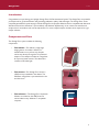
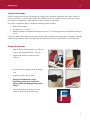
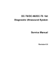
Omega Fluor™ and Omega Fluor Plus™ Gel Documentation Systems User Manual 01/2014 Table of Contents Section Omega Fluor Introduction Components and Parts Page 3 3 Omega Fluor System Specifications 4 System Placement 5 Setup Illustrations 5 Software Installation 6 Omega Fluor Plus Introduction Components and Parts Omega Fluor Plus System Specifications 12 12 13 System Placement 14 Setup Illustrations 14 Omega Fluor and Omega Fluor Plus Taking an Image 16 Omega Fluor Taking an Image on the Omega Fluor 17 Selecting Your Light Source 17 Capturing Your Image 18 Omega Fluor Plus Taking an Image on the Omega Fluor Plus 20 Selecting Your Light Source 20 Capturing Your Image 22 Omega Fluor and Omega Fluor Plus Overview of Software Features 23 Omega Fluor UV Cutoff Switch 27 Common Imaging Questions 28 Appendix A—Ordering Information 29 Appendix B—Routine Maintenance 30 Appendix C—Regulatory 33 Appendix D—Mitsubishi Electric P-95D Printer Driver Installation 36 Omega Fluor Appendix E—System Requirements 39 Omega Fluor Plus Appendix F—Installing or Changing Emission Filters 40 Appendix G—USB Installation Guide 41 Appendix H—Basic Tablet Operations 43 2 Omega Fluor 01/2014 Introduction Congratulations on purchasing your Aplegen Omega Fluor Gel Documentation System. The Omega Fluor is a powerful yet simple tool for gel documentation and generating publication quality, 16bit tiff images. The Omega Fluor comes completely assembled for quick startup. It includes Omega Fluor Acquisition Software which is compatible with Microsoft Windows XP and Vista, Windows 7 (32 and 64 bit), and Windows 8 (32bit only). It has a clean user interface and simple tools for annotations and contrast adjustments. For more in depth analysis, the data can be exported to a gel analysis software. Components and Parts The Omega Fluor system includes the following components: • The cabinet—The cabinet is a light tight imaging station. It includes a 302nm UV transilluminator on a pull out tray. Samples can be seen directly through the UV protected viewport. The viewport includes an orange filter for improved visual contrast. The cabinet also contains an EPI white light. • The camera—The Omega Fluor camera is a 5MP and is pre-installed in the cabinet. The 590/50nm orange filter is pre-assembled on the end of the lens • The software—The Omega Fluor Acquisition Software is included on the USB Drive and can be loaded on any Windows™ compatible computer. 3 Omega Fluor 01/2014 Omega Fluor System Specifications Specifications Camera Lens Field of View Cabinet Emission Filter Applications Certifications Product Footprint Computer Requirements • 5MP for high resolution images • USB connection for simple set up • Fast refresh rate for live imaging • High quality images ideal for downstream analysis 8mm F1.4 Lens 20 cm by 24 cm • 302 nm pull out UV transilluminator (or optional 365 nm) • UV viewing port • EPI white lights 590 nm • Fluorescent gel imaging • Visible gel imaging • Gel documentation CE; CSA; UL compliant 34.6cm x 31.1cm x 68.6cm Desktop Computers • Supported OS: Windows 8 32 bit; Windows 7/Vista 32 or 64 bit, Windows XP (with Microsoft .NET Framework 3.5) • Minimum hardware requirements: 1.4 GHz processor speed, 2GB RAM, 16 GB Free Hard Disk Space, 2 USB (camera and printer) Laptop Computers • Supported OS: Windows 8 32 bit; Windows 7/Vista 32 or 64 bit, Windows XP (with Microsoft .NET Framework 3.5) • Minimum hardware requirements: 1.4 GHz processor speed, 2GB RAM, 16 GB Free Hard Disk Space, 2 USB (camera and printer) 4 Omega Fluor 01/2014 System Placement As with all electrical instruments, the Omega Fluor imaging system should be located away from water, solvents, or corrosive materials, on a flat and stable surface with adequate clearance on all sides. The top of the system should have at least 10 cm clearance to allow sufficient air flow around the camera head. The system is intended for indoor use with the following ambient conditions: a. Altitude up to 2000 m; b. Temperature 5 °C to 40 °C; c. Maximum relative humidity 80% for temperatures up to 31 °C decreasing linearly to 50% relative humidity at 40 °C; Further, the system should be placed away from interfering electrical signals and magnetic fields. If possible, a dedicated electrical outlet should be used to eliminate electrical interference from other instrumentation in your laboratory. Setup Illustrations •Begin by placing the Omega Fluor on a flat, level surface with adequate clearance on all sides. •Plug the USB camera connection into the computer. •Connect the power supply and the AC adapter cord. • Plug the cord into a power outlet. • plegen recommends a surge A protecting powerstrip to protect against potential damage from power surges. •Install the Omega Fluor Software onto the computer which will run the instrument. 5 Omega Fluor 01/2014 Software Installation The Omega Fluor Acquisition Software is provided on the included USB drive. Installation should be completed by a user with administrator rights. A complete list of system requirements can be found in Appendix D. Windows 8, 32 Bit Installation To install the software on a Windows 8, 32 bit operation system you will need to disable the Secure Boot feature prior to installing the software and drivers. The Secure Boot feature is an advanced security feature new to the Windows 8 operating system. To disable the Secure Boot: • Open the Charms Bar, swipe with your finger from the far right side of the screen, to the left. • Select Settings. • Select Change PC Settings. • Select General. •Scroll down the list, Under Advanced Startup select Restart Now. The system will restart. 6 Omega Fluor • Select Troubleshoot. • Select Advanced Options. • Select Startup Settings. • Select Restart. •Use the USB keyboard to select number 7 (hit F7 or the number 7 key). The system will restart. You are now ready to install the printer driver. • •Turn on the printer and follow the directions that appear on the screen. 01/2014 To start, plug in the printer USB. 7 Omega Fluor 01/2014 With the Secure Boot disabled, plug in the USB. •Select the Omega Fluor Setup Program from the launch window. •Follow the directions on the screen. • You are now ready to use your Omega Fluor. 8 Omega Fluor 01/2014 Windows 7 Software Installation •To complete Windows 7 software installation, plug in the USB drive. • Follow the instructions on the screen. 1 2 3 4 5 A pop up may appear that says the Omega Fluor Camera has not passed Windows Logo testing. The camera driver is a standard camera driver and has been extensively tested to ensure compatibility. In addition, it is currently in process of Windows Logo verification. Click Continue Anyway to complete installation. 9 Omega Fluor 01/2014 Windows XP Software Installation •To install the software on a Windows XP machine, plug in the USB. •When prompted, select Omega Fluor Setup Program from the launch window. • Follow the instructions on the screen. 1 2 3 4 5 10 Omega Fluor 01/2014 You may also navigate directly to the OmegaFluorGDSSetup.exe through the Computer menu. • Select My Computer from the Application Menu • • Select the OmegaFluorGDS-Setup.exe and double click to run. Select the Omega Fluor (G:) drive The first time the camera is connected the Found New Hardware Wizard will pop up to install the camera driver. • To complete the installation select No not this time. • Select Install Software Automatically (Recommended). • When prompted click Finish to complete installation of the camera driver. A pop up may appear that says the Omega Fluor Camera has not passed Windows Logo testing. The camera driver is a standard camera driver and has been extensively tested to ensure compatibility. In addition, it is currently in process of Windows Logo verification. Click Continue Anyway to complete installation. 11 Omega Fluor Plus 01/2014 Introduction Congratulations on purchasing your Aplegen Omega Fluor Plus gel documentation system. The Omega Fluor Plus is a powerful yet simple tool for gel documentation and generating publication quality, 16bit tiff images. The Omega Fluor Plus comes completely assembled for quick startup, and includes Omega Fluor Acquisition Software. It has a clean user interface and simple tools for annotations and contrast adjustments. For more in depth analysis, the data can be exported to a gel analysis software. Components and Parts The Omega Fluor Plus system includes the following components: • The cabinet—The cabinet is a light tight imaging station. It includes a 302nm UV transilluminator on a pull out tray. The cabinet also contains an EPI white and EPI Blue light. • The camera—the Omega Fluor Plus camera is a 5MP, and comes installed on the cabinet. There is a 3 position filter wheel with an Orange 590/50 nm filter standard. • The software—The Omega Fluor Plus Acquisition Software is included on the USB Drive and can be loaded on any Windows™ compatible computer. 12 Omega Fluor Plus 01/2014 Omega Fluor Plus System Specifications Specifications Camera Lens Field of View Cabinet Emisssion Filter Applications Certifications Product Footprint • 5MP for high resolution images • USB connection for simple set up • Fast refresh rate for live imaging • High quality images ideal for downstream analysis 8mm F1.4 Lens 20 cm by 24 cm • 302 nm pull out UV transilluminator (or optional 365 nm) • EPI white lights 590 nm • Fluorescent gel imaging • Visible gel imaging • Gel documentation CE; CSA; UL compliant 34.6cm x 31.1cm x 68.6cm 13 Omega Fluor Plus 01/2014 System Placement As with all electrical instruments, the Omega Fluor Plus imaging system should be located away from water, solvents, or corrosive materials, on a flat and stable surface with adequate clearance on all sides. The top of the system should have at least 10cm clearance to allow sufficient air flow around the camera head. The system is intended for indoor use with the following ambient conditions: a. Altitude up to 2000 m; b. Temperature 5 °C to 40 °C; c. Maximum relative humidity 80 % for temperatures up to 31 °C decreasing linearly to 50% relative humidity at 40 °C; Further, the system should be placed away from interfering electrical signals and magnetic fields. If possible, a dedicated electrical outlet should be used to eliminate electrical interference from other instrumentation in your laboratory. Setup Illustrations • Begin by placing the Omega Fluor Plus on a flat, level surface with adequate clearance on all sides. Make sure to check inside the system and the tablet for additional packing materials and remove them prior to use. • Connect the camera cable. You will find it just below the tablet on the right side. 14 Omega Fluor Plus 01/2014 • Connect the power supplies. 1 Aplegen recommends a surge protecting powerstrip to protect against potential damage from power surges. 2 3 4 5 • Turn on the power to the tablet computer. Select the Omega Fluor tile from the startup screen. You are now ready to start using your Omega Fluor Plus. 15 Omega Fluor & Omega Fluor Plus 01/2014 Taking an Image The Omega Fluor Acquisition Software allows the user to take images with their Omega Fluor system, modify the visual aspects such as contrast and saturation, make general annotations and has simple arithmetic options. The user can also open and modify previously acquired images. Basic Imaging involves: 1.Centering your sample 2. Selecting your lighting source 3. Capturing your image Basic Applications The Omega Fluor is compatible with multiple sample types. Use the table below as a guide. UV Light Ethidium bromide SybR® Green Coomassie blue Protein gels Visible light gels Other UV gels White Light Conversion Screen Blue Light 16 Omega Fluor 01/2014 Taking an Image on the Omega Fluor Centering Your Image Place your gel either directly on the UV transilluminator or in one of the optional sample trays available from Aplegen. • Gel Handling Tray for UV Applications • Gel Handling Tray for White Light Applications • Blue Light Conversion Screen Selecting Your Light Source Use this table to determine the lighting source for your application. Dye Excitation Emission Ethidium Bromide 302/365 nm 590 nm Coomassie Blue White Light Silver Stain White Light SYBR® Gold Blue Light 540 nm SYBR® Green Blue Light 520 nm SYBR® Safe Blue Light 530 nm 302 nm 520 nm SYPRO® Ruby 302 nm or Blue Light 610 nm Deep Purple™ UV or Blue Light 610 nm GelStar® 17 Omega Fluor 01/2014 Capturing Your Image The Omega Fluor UV transilluminator emits at a wavelength of 302nm (365nm optional). It can be controlled through the Image Capture Window. Once you have selected the appropriate light source and sample tray or conversion screen, launch the Omega Fluor Acquisition Software. • Click Acquire. • Select UV light. • Click Auto Exposure or use the manual exposure icons to adjust the image preview. • When using Auto Exposure the rotating marquee will appear in the bottom left of the Image Capture window. 18 Omega Fluor • When the calculation is complete the marquee will change from red to green. • If satisfied with the preview, select Image Capture. Your image will be captured and open in a new window. 01/2014 Once the image is captured it can be further adjusted for contrast, annotations added, saved, and printed. 19 Omega Fluor Plus 01/2014 Taking an Image on the Omega Fluor Plus Centering Your Image Place your gel either directly on the UV transilluminator or in one of the optional sample trays available from Aplegen. • Gel Handling Tray—UV • Gel Handling Tray—White Light Conversion Screen Selecting Your Light Source Use this table to determine the lighting source for your application. Dye Excitation Emission Ethidium Bromide 302/365 nm 590 nm Coomassie Blue White Light Silver Stain White Light SYBR® Gold Blue Light 540 nm SYBR® Green Blue Light 520 nm SYBR® Safe Blue Light 530 nm 302 nm 520 nm SYPRO® Ruby 302 nm or Blue Light 610 nm Deep Purple™ UV or Blue Light 610 nm GelStar® 20 Omega Fluor Plus 01/2014 The Omega Fluor Plus has three lighting sources: the UV transilluminator, the Epi Blue lights, and the Epi White lights. • Begin the aquisition by selecting your light source. • Select your filter. • Click the Acquire icon. • The light source is controlled by the software. To turn on the light source, check the Illumination button. 21 Omega Fluor Plus 01/2014 Capturing Your Image • Click on the Auto Exposure icon for a preview of the image or use the manual exposure icons to adjust the image preview. • When using Auto Exposure the rotating marquee will appear in the bottom left of the Image Capture window. • When the calculation is complete the marquee will turn from red to green. • If satisfied with the preview, select the Image Capture button. Your image will be captured and open in a new window. Once the image is captured it can be further adjusted for contrast, annotations added, saved, and printed. 22 Omega Fluor & Omega Fluor Plus 01/2014 Overview of Software Features The Omega Fluor Software has a simple user interface. The top left Omega Fluor icon accesses the Application Menu, while all image acquisition and annotation functions can be accessed from the home tab. Software functions include: File Tab • Open—Open previously saved files. • Save—Save image file, or changes to files. Default file type is .tiff. • Save as—Save a copy of an image file, as either a .tiff or .jpeg, or to an alternative file location. • Close—Close the image file in the current tab. • Close all—Closes all open image files. Unsaved images will not close without prompting the user to save or discard. • Print Print—Print the currently open image tab. Page Setup—Change page layout and print options. Print Preview—Previews the page layout and how the image will appear on the page. • Create Flat—Create flat field correction file for image modification. • Apply Flat—Applies flat field correction to open image. • E-mail Settings—Configure the system settings for easy export of images. Contact your network administrator if you are unsure of the SMTP server or outgoing port. The e-mail address used will appear as the sender. • User Manual—Opens a PDF of the user manual. • About—Provides the user with the current software version number. Home Tab • Image Menu Acquire—Click the acquire button to launch the Image Capture Window. A preview of your sample will appear. Open—Opens an image from a saved file location. Save—Opens the Save or Save As dialogue boxes. Print—Opens the Print, Print Setup, or Print Preview Dialogue boxes. Crop—Opens the Crop Image tool. To crop , select the icon. A + sign will appear in place of the mouse arrow when hovering over the image. Click and drag the mouse across the desired area. A new image will open in a new tab. 23 Omega Fluor & Omega Fluor Plus 01/2014 Resize—An image can be resized up to 3 times its original size, or to a max size of 7776 – 5832 pixels. Resize to size—Manually enter the size in pixels of the image desired. • Width—Image size in the horizontal plane. • Height—Image size in the vertical plane. • Keep aspect ratio—Maintains the proportions of the original image Rotate • Rotate Right 90° •Rotate Left 90° •Rotate 180° •Rotate Arbitrary—Adjust the image angle via slide bar or by typing the desired angle in the text box. Flip Horizontal—Flip the image along the horizontal axis. Flip Vertical—Flip the image along the vertical axis. Image Info •Displayed Information—Image Width, Image Height, Bit Depth, Exposure Time (ms), Date Taken, Taken By, Comment. • E dit Image Information—Allows Edits to the Taken By and Comments Section of the Image Info. Undo—Undoes the last action completed by the tools in this menu. • Contrast Adjustments Menu Auto Contrast—Calculates a balanced contrast ratio. Negative—Gives the inverse of the image. Display Saturation—Oversaturated pixels appear in red, under-saturated pixels appear in green. Manual Contrast—Adjust black white and gamma levels via slider or entering number into text box. • Zoom Menu Zoom In—Zooms in on the image. Zoom Out—Zooms out on the image. Zoom Best Fit—Adjusts zoom to fill window. Displays % in the lower left corner of the window. Panning—Click and hold to move image right or left. 24 Omega Fluor & Omega Fluor Plus 01/2014 • Annotations Menu Pointer—This is the object selector. It allows selection of text boxes, objects, lines, etc in order to edit or delete them. For example, to change the color of a box, select the pointer, double click on the box to be changed, then select the color select tool and click on the color desired. Rectangle—Draw a box on the image. Ellipse—Draw a circle on the image. Line—Draw a line on the image. Pencil—Draw freehand. Text—Click on the text box to get a cursor. Click on the image where you want the test to appear and a text box will open. Select font and make edits to the text within the box. Rotate Clockwise—Rotates text box or other selected object clockwise. Rotate Counterclockwise—Rotates text box or other selected object counterclockwise. Pen Color—Select the color for objects or lines. Pen Width—Select the width of the line for your objects or lines. Delete—Deletes the selected object. To select an object, use the pointer, click on the desired object, then click on the Delete icon. Undo—Undoes the last action. Redo—Redoes the last action. • Send File Menu—Use to send files. Email must be setup and file saved before it can be sent. See page 17 for instructions on setting up the send e-mail option. •The Image Capture Window—Clicking the Acquire icon on the Home Tab launches the Image Capture Window. UV Light—Turns on the UV light for excitation of fluorescent dyes. Manual Exposure—Select an exposure time by sliding the tab along the manual exposure bar or by entering a number into the box. The range of exposure times is: 1-2394ms. Auto Exposure—Automatically determine optimal exposure time. An animated marquee appears during the calculation process. When the animation is red, the auto exposure is calculating. When the animation turns green and says “Auto exposure completed!” the system is ready to image. Show Grid—A 4x4 grid will be overlaid on the image. 25 Omega Fluor & Omega Fluor Plus 01/2014 Zoom In—Zoom in on the desired area, the capture size is indicated on the lower left frame. Zoom Out—Zoom back out up to the original size. Capture Image—Capture the image at the selected parameters. 26 Omega Fluor & Omega Fluor Plus 01/2014 Omega Fluor UV Cutoff Switch The Omega Fluor has a UV cutoff switch to protect against accidental UV exposure when opening the cabinet door. The cutoff switch can be overridden to allow the user to visualize or excise bands. Before you override the UV cutoff switch make sure you are wearing the proper UV protective equipment. UV light can damage living tissue. To override the cutoff switch: 1. Open the door and pull out the UV transilluminator door. 2. Place your sample on the UV surface. 3. Slide the UV transilluminator in and close the door. 4. Launch the software, click Acquire and select UV light. The light will automatically shut off after 5 minutes. If you need more time, select UV light again. 27 Omega Fluor & Omega Fluor Plus 01/2014 Common Imaging Questions What is the difference between saving images as a .tiff or a .jpeg? The main difference between a .tiff and a .jpeg is the amount of data processing and data compression. While the .tiff format retains information on saturation and contrast it does not compress the data. This means the .tiff format retains all of the detail in the raw image data file. The .tiff format can be saved as 8 bit or 16 bit depending on the amount of data that is collected by the sensor. The amount of data can be considerable. The .jpeg file by contrast, compresses the image into an 8 bit format. This format has reduced detail but is quickly read by image processing software, and the smaller image size allows for increased storage capacity and ease of sharing. Compression is a bit of a misnomer, as once the data has been compressed, it cannot be returned to its original state. I saved my image as a .jpeg and now I cannot make changes to my annotations, why? When you save your image as a .jpeg the image both the image data and the annotation data are compressed into a single 24 bit rgb file. The annotations have functionally become part of the image. If you save the image as a .tiff the annotations are saved as a separate part of the file and can be edited by clicking on the box to select it, and making the changes as desired. My image seems to be fuzzy, unclear, or unfocused. How can I focus the lens? The lens does not have a focus ring and comes pre-assembled with the correct backfocus. If the calibration is off, this can be corrected by following the procedure in Appendix B. I see a half moon shape on my image, bright blur, or other artifact in my image. What’s wrong? The most common cause of these artifacts are light leaks. In order to create a light tight seal around the lens there is a rubber gasket. Over time this rubber will age and cracks can form. Please follow the procedure in Appendix B, Replacing the Rubber Lens Gasket. When I look through the View Port I can see UV bulbs, but they don’t appear in my final image. Why not? he orange filter on the view port blocks UV an improves visual contrast. However it does not block all wavelengths T of light that the bulbs emit. Therefore, the bulbs are still visible. The emission filter on the end of the Omega Fluor camera lens by contrast eliminates all emissions, except in the 590/50nm range, so the bulbs are not visible in the final image. 28 Omega Fluor & Omega Fluor Plus 01/2014 Appendix A—Ordering Information Product Description Omega Fluor 302 nm configuration Includes imaging system with cabinet, camera and trans 302 nm UV and EPI White Light sources, and Omega Fluor capture software. Omega Fluor 365 nm configuration Includes imaging system with cabinet, camera and trans 365 nm UV and EPI White Light sources, and Omega Fluor capture software. Omega Fluor Plus 302 nm configuration Includes imaging system with cabinet, camera and trans 302 nm UV and EPI White Light sources, and Omega Fluor Plus capture software. Omega Fluor Plus 365 nm configuration Includes imaging system with cabinet, camera and trans 365 nm UV and EPI White Light sources, and Omega Fluor Plus capture software. Part Number Accessories Thermal Printer Print Method: Thermal printing on thermal sensitive paper; Dot Density: 1280 dot/100 mm (325 dpi). USB connection. Thermal Paper 4 rolls Gel Tray Gel Handling Tray for UV excited gels White Light Conversion Screen White light conversion screen for gels requiring transwhite illumination Blue Light Conversion Screen Converts UV light to blue light for use with Safe Dyes Desktop computer •O perating system: Windows 8 32 bit, Windows 7 32 or 64-bit, Windows Vista 32 or 64-bit, Windows XP (with Microsoft .NET Framework 3.5). •M inimum hardware requirements: 1.4 GHz processor speed, 1GB RAM, 16 GB Free Hard Disk Space, 2 USB (camera and printer) Laptop Computer • Operating system: Windows 8 32 bit, Windows 7 32 or 64-bit, Windows Vista 32 or 64 bit, Windows XP (with Microsoft .NET Framework 3.5). • Minimum hardware requirements: 1.4 GHz processor speed, 2GB RAM, 16 GB Free Hard Disk Space, 2 USB (camera and printer) 29 Omega Fluor & Omega Fluor Plus 01/2014 Appendix B—Routine Maintenance Cleaning the Omega Fluor or Omega Fluor Plus Basic care is all that is required to keep your Omega Fluor or Omega Fluor Plus in great shape. Clean up any spills as they happen. Wipe down the UV glass with a soft cloth only to prevent scratching. A simple green solution can be used to clean heavier soil. Replacing the UV Bulbs 1. Disconnect the power to the Omega Fluor or Omega Fluor Plus. 2. Open the main door and pull out the UV transilluminator. 3. Remove the 4 screws on the two sides of the UV transilluminator. 4. Remove the top cover. Exercise caution as the top cover has a glass plate. 5. Replace the failed bulb. 6. Reinstall the UV transilluminator top cover and close the UV transilluminator drawer. Replacing the Rubber Lens Gasket 1. Ensure that the system is powered down. 2.Unscrew the camera attachment knob at the back of the system. Keep one hand on the camera to prevent dropping. 3. Gently remove the camera from the gasket. 4.Using a Phillips head screwdriver remove the 4 screws from the top plate, holding the gasket in placee. 5. Remove and discard the rubber gasket. 6.Center the new gasket in place. There are pre-cut screw holes in the gasket, ensure they line up with the corresponding holes on the cabinet. 7. Replace the top plate and insert the 4 screws. 8. Replace the camera so that the gasket is snug and flush on the lens flashing. 9. Perform the Lens Calibration Procedure. Omega Fluor or Omega Fluor Plus Lens Calibration Procedure The lens on the Omega Fluor or Omega Fluor Plus is pre-assembled on the cabinet and calibrated prior to shipment. However, it may occasional become necessary to recalibrate the lens, after changing the gasket for example. To calibrate the lens follow the procedure here. 1.Note the lens focus ring markings “NEAR “ and “FAR.” 30 Omega Fluor & Omega Fluor Plus 2. Place a target with high resolution features in the center of the field of view. Most business cards are adequate for this step. You may leave the door open and focus by ambient light. 3.Launch the software, click on the acquire button, then zoom in completely in the preview window. The zoom option will grey out when you reach the end of the range. 4. Click on the Auto Expose option. 5. Loosen the focus ring locking screw. 6.Adjust focus until image is clearly focused then turn focus ring until the image is slightly out of focus in the “NEAR” direction. 01/2014 31 Omega Fluor & Omega Fluor Plus 7.Slowly adjust focus ring only in the “FAR” direction until the image is perfectly focused. 8.Lock focus ring in place with focus ring locking screw. 9. Remove target. 10.Zoom out completely (tool will grey out). 11. Take a test image to verify focus. 01/2014 32 Omega Fluor & Omega Fluor Plus 01/2014 Appendix C—Regulatory Waste Electrical and Electronic Equipment (WEEE) ENG This symbol indicates that the waste of electrical and electronic equipment must not be disposed as unsorted municipal waste and must be collected separately. Please contact an authorized representative of the manufacturer for information concerning the decommissioning of your equipment. FRA GER ITA SPA SWE Ce symbole indique que les déchets relatifs à l’équipement électrique et électronique ne doivent pas être jetés comme les ordures ménagères non-triées et doivent être collectés séparément . Contactez un représentant agréé du fabricant pour obtenir des informations sur la mise au rebut de votre équipement. Dieses Symbol kennzeichnet elektrische und elektronische Geräte, die nicht mit dem gewöhnlichen, unsortierten Hausmüll entsorgt werden dürfen, sondern separat behandelt werden müssen. Bitte nehmen Sie Kontakt mit einem autorisierten Beauftragten des Herstellers auf, um Informationen hinsichtlich der Entsorgung Ihres Gerätes zu erhalten. Questo simbolo indica che i rifiuti derivanti da apparecchiature elettriche ed elettroniche non devono essere smaltiti come rifiuti municipali indifferenziati e devono invece essere raccolti separatamente. Per informazioni relative alle modalità di smantellamento delle apparecchiature fuori uso, contattare un rappresentante autorizzato del fabbricante. Este símbolo indica que el equipo eléctrico y electrónico no debe tirarse con los desechos domésticos y debe tratarse por separado. Contacte con el representante local del fabricante para obtener más información sobre la forma de desechar el equipo. Denna symbol anger att elektriska och elektroniska utrustningar inte får avyttras som osorterat hushållsavfall och måste samlas in separat . Var god kontakta en auktoriserad tillverkarrepresentant för information angående avyttring av utrustningen. CE Conformity The following Omega Fluor Imaging Systems, Models: Omega Fluor and Omega Fluor Plus Are in conformity with the provisions of the following EC Directives, including all amendments, and national legislation implementing these directives: Low Voltage Directive 2006/95/EC EMC Directive 2004/108/EC And that the following harmonized standards have been applied: EN61010-1: 2001 EN61326-1: 1997+A1:1998+A2:2001+A3:2003 Class A EN61000-4-2,EN61000-4-3, EN61000-4-4, EN61000-4-5, EN61000-4-6, EN61000-4-11 Protection category: IP20 according IEC 60529 33 Omega Fluor & Omega Fluor Plus 01/2014 Copyright and Trademark Information All goods and services are sold subject to the terms and conditions of sale of the company within Aplegen International Inc. which supplies them. Aplegen, Inc. reserves the right, subject to any regulatory and contractual approval, if required, to make changes in specifications and features shown herein, or discontinue the product described at any time without notice or obligation. Contact an Aplegen, Inc. representative for the current information. Aplegen, Inc. 5880 West Las Positas Blvd., Suite 34 Pleasanton, CA 94588-8552 USA Phone: Fax: Email: (925) 225-2100 (925) 463-3416 [email protected] Tech Support: (925) 463-3410 Tech Support Fax: (925) 463-3416 Email: [email protected] Safety Warnings UV Safety Precautions CAUTION Because U.V. radiation can cause serious damage to unprotected eyes and skin, we recommend to wear U.V. protection glasses or face shield. The Omega Fluor and Omega Fluor Plus systems come with a built-in Ultra-Violet (UV 200-400nm) Trans-illuminator inside the system. Exposure to UV radiation can cause permanent damage to the eyes and skin. The system enclosure confines the radiation within the system and shields the user from exposure. The system is also equipped with a twoway safety interlock switch which automatically cuts off the power to the trans-illuminator when the door is open during normal use. The Omega Fluor and Omega Fluor Plus imaging systems belong to Class A equipment, and fulfills the limit values of table 3 but not table 4 of EN 61326:1997+A1+A2+A3. It may become necessary to defeat the safety lock or operate the transilluminator outside the system for service. In this case, be sure to use the following safety precautions: •Always wear UV-protected eyewear that is specified by the manufacturer as providing protection at the wavelength(s) used, making sure that the eyewear protects any areas wear radiation may come through (UV sunglasses may not prevent UV radiation from coming in through the sides or around the lenses). • Always cover all skin that may be exposed to UV light, especially the face, neck, hands, and arms. • Always make sure that any UV protection devices (such as the safety switch on the light cabinet apparatus) are working properly. If not, discontinue use until the device(s) are properly repaired. • Please use only UV lamps in the trans-illuminator. 34 Omega Fluor & Omega Fluor Plus 01/2014 Electrical Safety Precautions Be sure to take proper precautions when handling any electrical equipment. NEVER work on any live circuit, fixture, receptacle, or switch. Safety rules you should follow whenever working with any electrical appliance include: • Always shut off power at the main disconnect before changing a fuse. •Always shut off power to the circuit before repairing or replacing a switch, receptacle, or fixture. •Always tape over the main switch, empty fuse socket, or circuit breaker you are working on. •Always check that the circuit is dead before beginning work on it. Using a circuit tester or voltmeter can help you determine this. • Always unplug any appliance before repairing it. The earth terminal, intended for connection to an external protective conductor for protection against electric shock in case of a fault, is located on the inside of the back panel. Hot Surface Warning Under normal conditions, the temperature of glass surface of UV transilluminator is below 50 °C and safe to touch. However, if the system malfunctions, it is possible that the glass surface temperature exceeds 80°C. Please exercise caution when touch the glass surface with hand when this occurs. System Specifications Camera resolution 5 MP Epi-illumination White LED Trans-Illumination 302 nm/365nm Lens 8mm/F1.4, ultra low distortion Maximum Field of View 20 cm x 24 cm Image output 16-bit Tiff, Jpeg Power requirement DC 12V 5A < 60 W Dimensions (W x D x H) 34.6cm x 31.1cm x 68.6cm Weight 21.3 kg 35 Omega Fluor & Omega Fluor Plus 01/2014 Appendix D—Mitsubishi Electric P-95D Printer Driver Installation Windows 8 Driver Signature Enforcement is a new feature of Windows 8 that has certain signature requirements not yet implemented in the Mitsubishi Electric P-95D Printer. In order to install the printer driver you must disable the Driver Signature Enforcement on startup, install the driver, and then reboot the system. The Driver Signature Enforcement will reset upon rebooting, but once the driver has been installed it will remain. You will need a USB keyboard to complete the driver installation. To install the Mitsubishi Electric P-95D Printer Driver please take the following steps: • Open the Charms Bar, swipe with your finger from the far right side of the screen, to the left. • Select Settings. • Select Change PC Settings. • Select General. •Scroll down the list, Under Advanced Startup select Restart Now. The system will restart. 36 Omega Fluor & Omega Fluor Plus • Select Troubleshoot. • Select Advanced Options. • Select Startup Settings. • Select Restart. •Use the USB keyboard to select number 7 (hit F7 or the number 7 key). The system will restart. You are now ready to install the printer driver. • •Turn on the printer and follow the directions that appear on the screen. 01/2014 To start, plug in the printer USB. 37 Omega Fluor & Omega Fluor Plus 01/2014 •Or, you may install the printer from the control panel. To reach the control panel, open the Charms bar, select Control Panel. Detailed driver installation instructions are available in the Mitsubishi Electric P-95D Printer Installation Materials. 38 Omega Fluor 01/2014 Appendix E—System Requirements The following are the minimum system requirements to run the Omega Fluor system software. Aplegen recommends using a system with higher than the minimum requirements for optimum performance. • Windows XP, SP3 and Windows 7, Home or Pro Editions •.net Framework 3.5 or above •Pentium 300-megahertz (MHz) processor or faster • 128 megabytes (MB) of RAM or greater • 1.5 gigabytes (GB) Hard Drive or greater • At least one available USB port in addition to those needed for the keyboard, mouse, and optional printer. 39 Omega Fluor Plus 01/2014 Appendix F—Installing or Changing Emission Filters The Omega Fluor Plus has a three position sliding filter wheel. Optional filters may be purchased from Aplegen and installed by the user for those applications that require an emission band path that is different from the standard Orange filter (590/50nm). Installation is quick and requires no tools. Aplegen recommends that you wear disposable glove while handling filters to avoid getting fingerprints on the glass. In the case that prints are left behind they can be cleaned with ethanol and lens paper. Do not use regular paper towels as these may scratch the filter. First, locate an open filter position. When looking up into the cabinet you will see the Orange filter in Position 1. Position 2 is the middle position, and Position 3 is on the right hand side as you are looking into the cabinet. 2 1 3 Remove the lens from the packaging and insert it into the open filter position. The filter ring is threaded. Turn the filter clockwise to tighten. Take care not to cross the threads. 40 Omega Fluor Plus 01/2014 Appendix G—USB Hub Installation Guide The Omega Fluor Plus comes with an optional USB hub for those systems that are not going to be connected to a wireless network. Please use the following guide for easy installation of the hub. 1.Affix the USB hub to a convenient location on the cabinet. The Hub includes double stick tape for placement. 2. Remove the camera cable from the rear cubby. 3.Disconnect the camera USB from the right angle adapter. 4.Slide the camera USB cable through the cable guide and plug it into the Hub. 41 Omega Fluor Plus 01/2014 5. Connect the Hub USB mini cable to the Hub. 6.Connect the Hub USB mini cable to the right angle adapter. 7. Plug in the USB Hub power supply. 8.Roll up excess USB cable and tuck it back into the rear cubby. 42 Omega Fluor Plus 01/2014 Appendix H—Basic Tablet Operations The Omega Fluor Plus a touch screen tablet PC to run the imaging station. For in depth directions refer to the Acer Tablet User Manual. However, here are some basic navigation tips to help you get started. • Use your finger as you would a mouse. • One touch or tap to select. • To Scroll tap once, then drag the scroll bar as desired. • Double tap an icon to launch an application. • To “right click” touch and hold your finger to the screen. A circle will appear around the point, when it completes, lift your finger and the options menu will appear. • To exit the menu, tap anywhere on the desktop. • To enter text information touch and hold on the far left side of the screen. This will cause the virtual keyboard to appear as a tab. Touch the tab to select. • The windows button on the lower left side of the tablet can be used to open the Windows Main Menu. You can use the shortcut Windows logo key (+D). Please see Omega Fluor Windows 8 Software Installation to see the icon. • For ease of installation printer drivers for the Mitsubishi P93D Thermal Printer have been pre-installed. To complete the installation simply plug in the USB cable and follow the prompts on the screen. 43