1
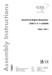
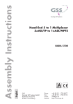
Head-End Digital Modulator COFDM - PAL KLASSE HDMT 2180 P CI English CLASS GSS Grundig SAT Systems GmbH Beuthener Strasse 43 D-90471 Nuremberg Phone: Fax: E-mail: Internet: +49 (0) 911 / 703 8877 +49 (0) 911 / 703 9210 [email protected] http://www.gss.de Contents 1 Safety regulations and notes............................................................................... 4 2 General information........................................................................................... 5 2.1 Packing contents.................................................................................... 5 2.2 Meaning of the symbols used.................................................................. 5 2.3 Technical data....................................................................................... 5 2.4 Description........................................................................................... 6 2.5 Software query...................................................................................... 7 3 Assembly........................................................................................................... 7 3.1 Installing the cassette.............................................................................. 7 3.2 EMC regulations.................................................................................... 8 3.3 Overview of the cassette......................................................................... 9 3.4 Connecting the cassette.......................................................................... 9 3.5 Updating the software............................................................................ 9 3.6 Retrofitting a CA module....................................................................... 10 4 The control panel at a glance............................................................................ 11 4.1 Menu items......................................................................................... 11 4.2 Control panel...................................................................................... 11 5 Programming................................................................................................... 12 5.1 Preparation......................................................................................... 12 5.2 Programming procedure....................................................................... 12 5.3 Programming the cassette .................................................................... 16 Selecting the cassette, displaying the software version.............................. 16 Selecting the channel strip.................................................................... 17 Switching the modulator off or on.......................................................... 18 Adjusting the output levels of the channel strips........................................ 18 Setting the TV standard of the output signal . .......................................... 19 Selecting channel / frequency setting..................................................... 19 Setting the output channel..................................................................... 20 Setting the fine-tuning........................................................................... 20 Setting the output frequency.................................................................. 20 Selecting the Tuner (only channel strip B)................................................ 21 Selecting channel or frequency setting (input).......................................... 21 Configuring the CA module (only channel strip A).................................... 21 Setting the input channel....................................................................... 23 Setting the input frequency.................................................................... 23 Setting the input signal......................................................................... 24 Setting the input symbol rate................................................................. 24 Channel selection................................................................................ 25 Selecting the TV station sound............................................................... 26 Setting the volume level........................................................................ 26 - 2 - HDMT 2180 P CI Setting the audio mode......................................................................... 26 Setting the audio output........................................................................ 26 Adjusting the picture format.................................................................. 27 Switching teletext mode off/on.............................................................. 27 Activating test lines.............................................................................. 28 Locking the regional window................................................................. 28 Subtitle settings.................................................................................... 28 Setting the time zone and summer time................................................... 30 Setting time-controlled, alternative channels............................................. 31 Switching the timer on and off............................................................... 31 Setting the duty cycle........................................................................... 31 Setting the days of the week.................................................................. 32 Selecting channel or frequency setting (timer, input)................................. 32 Selecting input channel or input frequency setting (timer).......................... 33 Setting the input signal / symbol rate (timer)........................................... 33 Channel selection (timer)....................................................................... 33 Selecting the TV station sound / Setting the volume level (timer)................. 34 Saving settings.................................................................................... 34 6 Final procedures............................................................................................... 35 7 Channel and frequency tables........................................................................... 36 - 3 - HDMT 2180 P CI 1 Safety regulations and notes • Assembly, installation and servicing should be carried out by authorised electricians. • Switch off the operating voltage of the system before beginning with assembly or service work or pull out the mains plug. • Do not perform installation and service work during thunderstorms. • Install the system so it will not be able to vibrate… - in a dust-free, dry environment -in such a manner that it is protected from moisture, fumes, splashing water and dampness - somewhere protected from direct sunlight - not within the immediate vicinity of heat sources - in an ambient temperature of 0 °C to +50 °C. In case of the formation of condensation wait until the system is completely dried. • Ensure that the head-end station is adequately ventilated. Do not cover the ventilation slots. • Beware of short circuits • No liability is accepted for any damage caused by faulty connections or inappropriate handling. • Observe the relevant standards, regulations and guidelines on the installation and operation of antenna systems. • The standards IEC/EN/DIN EN 50083 and IEC/EN/DIN EN 60728 must be observed. • For further information please read the assembly instructions for the headend station used. • Test the software versions of the head-end station and the cassette and update them if necessary. The current software versions can be found at ”www.gss.de”. Take action to prevent static discharge when working on the device! Electronic devices should never be disposed of in the household rubbish. In accordance with directive 2002/96/EC of the European Parliament and the European Council from January 27, 2003 which addresses old electronic and electrical devices, such devices must be disposed of at a designated collection facility. At the end of its service life, please take your device to one of these public collection facilities for proper disposal. - 4 - HDMT 2180 P CI 2 General information 2.1 Packing contents 1 cassette HDMT 2180 P CI 2 HF cables 1 Brief assembly instructions 2.2 Meaning of the symbols used 1 CD (assembly instructions) Important note —> General note • 2.3 Technical data The devices meet the following EU directives: 2006/95/EC, 2004/108/EC The product fulfils the guidelines and standards for CE labelling. Unless otherwise noted all values are specified as “typical”. HF input Frequency range:......................................................... 177,5 … 858 MHz Level range:..............................................................60 dBμV … 80 dBμV Channels DVB-T:................................................... C5 … C12, C21 … C69 Bandwidth DVB-T................................................................. 7MHz/8MHz Modulation / Symbol rate DVB-T:.................................. acc. to EN 300744 Channels DVB-C:.....................................................................C5 … C69 Modulation DVB-C:........................................... QAM 16/32/64/128/256 Symbol rate DVB-C:.............................................................. 1…7 MBaud HF output Channels:....................................................... C2 … C69 (incl. S2 … S41) Frequency range:............................................ 48.25 MHz … 855.25 MHz Standard:.......................................................................... CCIR PAL B/G Output level:.............................................................................. 98 dBμV Output level attenuation:.............................................................0 … 7 dB Output impedance:.......................................................................... 75 Ω Performing works - 5 - HDMT 2180 P CI Video interference level:.................................................................. 57 dB Video band width:.......................................................... 20 Hz … 5 MHz Audio interference level:..................................................................60 dB Audio band width:.......................................................... 40 Hz … 15 kHz Connections HF inputs:............................................................................2 IEC sockets HF output:............................................................................. 1 IEC socket Connection strip (10-pin):....................for supply voltages and control circuits RS 232 socket:...................................... serial interface for software update Conditional access:................................1 (2 channels can be descrambled) 2.4 Description The twin transmodulator cassette converts all stations modulated according to DVB-T or DVB-C standard into two PAL-modulated cable signals. The cassette has two HF inputs and one HF output. It is equipped with two channel strips. Each channel strip consists of a digital tuner, a digital signal preparation unit and a modulator. The cassette‘s channel strips are indicated by “Bx …A“ or “Bx …B” in the control unit display. The channel strip “A” can descramble scrambled channels via a corresponding CA module. Depending on the CA module and the smart card, two channels can be descrambled simultaneously with one CA module, with the second one supplied via channel strip “B”. Time controlled channel switching is possible by the integrated time control. The control of the cassette takes place via the control unit of the head-end station. Two LEDs provide an indication of the SAT IF input signal quality based on their colour. If the data of channel strip ”A” are used in channel strip ”B” the status LED of channel strip ”B” is switched off. The prepared input signals reach the HF output collector of the head-end station via the HF output socket. The common output level of the channel strips can be set at the HF output collector of the head-end station. When the head-end station is switched on, the two-line LC display briefly shows the software version of the control unit. To operate this cassette the software version of the control unit must be “V 41” or higher. You can find the current operating software for the control unit and the cassette, the software “BE-Flash” and the current assembly instructions on the website “www.gss.de”. The cassette is designed for use in the following head-end stations: STC 1200, STC 816 and PST 19-1. - 6 - HDMT 2180 P CI 2.5 Software query Control unit If necessary, you can activate the indication of the software version of the control unit manually: • Press any two keys on the control unit of the head-end station simultaneously until the display goes dark and afterwards the software version, e.g. “V 41” appears. Cassette After activating the cassette the software version of the cassette is displayed (see page 16). 3 Assembly 3.1 Installing the cassette – Ensure the head-end station is mounted so it will not be able to vibrate. Avoid, for example, mounting the head-end station onto a lift shaft or any other wall or floor construction that vibrates in a similar way. – Before installing or changing a cassette unplug the power cable from the mains power socket. • Remove the fastening screws 1 of an unoccupied slot from the bracket of the head-end station. • Insert the cassette in this slot and push it into the housing. • Align the cassette and apply slight pressure to connect it to the connections of the board and the HF bus bar. • Fasten the cassette with the screws 1. - 7 - HDMT 2180 P CI 1 HYBRID-VERSTÄRKER KASSETTE KASSETTE KASSETTE KASSETTE KASSETTE KASSETTE KASSETTE KASSETTE KASSETTE KASSETTE KASSETTE KASSETTE 0° ACHTUNG! Vor dem Kassettenwechsel unbedingt denNetzstecker ziehen. MESSAUSGANG –20 dBµV CAUTION! Before changing cassettes remove mains plug. AUSGANG max. 106 dBµV Grundig SAT Systems 1 3.2 EMC regulations KLASSE To comply with the current EMC regulations, it is necessary to connect the lines leading in and out of the head-end station using cable terminals. CLASS The attenuation of shielding of the connection lines must meet the requirements for “Class A”. When mounting the cassette in a head-end station which is installed in a 19” cabinet, make sure the connections leading in and out for the 19” cabinet are made using cable terminals. • Insert the required number of cable terminals in the openings provided in the head-end station or in the 19” cabinet. —> Cable terminals are not included in the scope of delivery. Tighten the nut on the cable terminal until the teeth on the lock washer have penetrated the exterior coating and a good connection is made between the housing and cable terminal. - 8 - HDMT 2180 P CI 3.3 Overview of the cassette 12 5 6 1 2 3 4 5 6 3.4 Connecting the cassette • Connect the HF input 3 (channel strip “A”) and HF input “B”) to the respective outputs of the HF input distributor. • Connect the head-end station to the mains power supply. 3.5 Updating the software The RS 232 interface of the cassette $ enables you to use a PC or a notebook and the “BE-Flash” software to update the software of the cassette. You can find the “BE-Flash” software and the current operating software of the cassette at the website “www.gss.de”. HF input (channel strip “B”) Status LED of the channel strip “B” HF input (channel strip “A”) Status LED of the channel strip “A” D-SUB socket “RS 232“ Slot for a CA module 1 (channel strip • Use a “one-to-one cable” to connect the cassette’s RS 232 interface and the PC according to the wiring scheme below. 9-pin D-SUB plug 34 1 2 3 4 5 6 7 8 9 1 2 3 4 5 6 7 8 9 9-pin D-SUB socket —> If necessary use a standard RS-232/USB adapter. • Start the “BE-Flash” software and update the software of the cassette. - 9 - HDMT 2180 P CI 3.6 Retrofitting a CA module The cassette is equipped with a common interface. It allows you to connect a CA module for various scrambling systems and service providers. Scrambled channels can only be descrambled with a CA module suitable for the scrambling system and the corresponding smart card. The smart card contains all the information for authorisation, descrambling and subscription. – Check with the distributor or manufacturer of the CA module to be used to ensure that it is suitable for descrambling several channels. – The hardware and software of this cassette have been thoroughly prepared and tested. – Any changes made by program providers to the structures in the program data might impair or even prevent this function. – When working with the CA module, please read the corresponding operating manual from the respective provider. • Insert the smart card 1 into the CA module 2 so that the chip 3 on the smart card faces the thicker side (top) of the CA module. • Insert the CA module into the guide rails of the CA slot 4 with the top side of the CA module facing the top side of the cassette. • Push the CA module without canting into the guide rails of the CA slot 4 and contact it to the common interface. 4 2 3 1 - 10 - HDMT 2180 P CI 4 The control panel at a glance 4.1 Menu items Program the cassette using the buttons on the control unit of the head-end station. The two-line display of the control unit then shows the menus. The parameters and functions to be set are underlined. Use the – Cassette – Channel strip – Modulator / output level – TV standard – Channel- / frequency selection – Output channel / output frequency – Input channel / input frequency – Input signal / - symbol rate – Channel selection – TV station sound / Volume – Audio mode / Audio output – Picture format / Teletext – Test lines – Regional window – Subtitle – Time zone and summer time – Timer settings 4.2 Control panel The key pad on the head-end station is used to scroll through the menus and menu items one at a time: BE-Remote V41 please wait . . . scrolls forward through the menus. select parameters in the menus. set values, initiate actions. selects sub-menus. scrolls backward through the menus. saves all entries. key to select the following main menu items: - 11 - HDMT 2180 P CI 5 Programming 5.1 Preparation • Test the software versions of the head-end station and the cassette and update them if necessary. The current software versions can be found on the website “www.gss.de”. • Connect the test receiver to the HF output or the test output of the head-end station. • Set the output channel / output frequency of the cassette (page 20) and adjust the TV test receiver to this channel / this frequency. • Switch on the modulator if necessary (page 18). • Balance the output levels of the channel strips “A” and “B” if the difference in level is ≥ 1 dB (see chapter “Modulator settings / Adjusting the output levels of the channel strips”, page 18). 5.2 Programming procedure Ein / On BE–Remote V 41 please wait … t > 10 s Box … …… ……… …… + Box 4 V4 Bx 1A TWIN-SAT Böx 4 TWIN-SAT Box 5 .............. C5-12,S3-24 C07 C5-12,S3-24 C07 .............. .............. T/C-PAL ––– A Page 15 B Bx 4A/B T/C-PAL ZDF C69 Bx 4A/B MODULATOR on Level -3 on / off Bx 4A/B CCIR *) NORM 5.5 FM A/B ◀/▶ 0 … - 7 dB - 12 - CCIR 5.5 FM … OIRT 6.5/6.3 FM HDMT 2180 P CI Bx 4A/B MODULATOR Level -3 on ◀/▶ 0 … - 7 dB on / off Bx 4A/B CCIR *) NORM 5.5 FM CCIR 5.5 FM … OIRT 6.5/6.3 FM *) HDMT 2180 P CI kann nur Norm CCIR erzeugen. Bx 4A/B HDMT 2180 P CI is only able to generate CCIR standard. OUTPUT Channel Channel / Freq. Bx 4A/B OUTPUT C69 ▶ Bx 4A/B ▶ C69 Fine Bx 4B Bx 4B Bx 4A OUTPUT 0 - 64 … 63 INPUT Tuner Line B Tuner A / Tuner B nur Kanalzug B only channel strip B Tuner B Bx 4A/B INPUT Channel > ▶ Tuner A Bx 4A CA-MENU Bx 4A MENU ▶ nur mit CA-Modul / only with CA module Channel / Freq. 1/6 Information **) ◀/▶ nur Kanalzug A / only channel strip A **) Die angezeigte Information ist abhängig vom verwendeten CA-Modul. The information displayed is dependent on the CA module used. Bx 4A/B C66 (834.0) Bx 4A/B INPUT ▶ Bx 4A OK ◀ C66 SYMBOL ◀/▶ COFDM 8MHz 6900***) INPUT 0 OK ***) nur bei QAM / only at QAM COFDM 7…8MHZ QAM 16…256 Bx 4A/B 01/09 + TV ZDF - 13 - HDMT 2180 P CI COFDM 7…8MHZ QAM 16…256 Bx 4A/B 01/09 + TV ZDF Bx 4A/B 01/02 AUDIO deu Bx 4A/B mpeg ◀/▶ - 6 dB AUDIO + 6 … - 26 dB ◀/▶ DUAL norm normal / swap mpeg … stereo Bx 4A/B VIDEO WSS on TXT on ◀/▶ on / off on / off Bx 4A/B TESTLINES on Bx 4A/B PIDS dynamic dynamic / fixed Bx 4A/B SUBTITLE Bx 4A/B off txt 150 Bx 4A/B dvb Bx 4A/B 14:20:11 ? TIME + 01 S ◀/▶ SUBTITLE west SUBTITLE 01 / 02 "deu" Bx 4A/B SUBTITLE black 40 / 10 - 12 … + 12 S / – - 14 - ◀/▶ ◀/▶ off / txt / dvb / black 100 … n west / east ◀/▶ Sprachauswahl Language selection ◀/▶ HDMT 2180 P CI Bx 4A/B 14:20:11 ? Bx 4A/B TIME + 01 S ◀/▶ - 12 … + 12 S/– TIMER off Bx 4A/B on / off TIMER ◀/▶ 05:00 – 10:00 on M A B Page 12 nicht bei Kombination Kanalzug B und Tuner A not in combination channel strip B with tuner A Bx 4A/B TIMER Days ◀/▶ MTWTFSS TIMER INPUT Channel Channel / Freq. INPUT ▶ TIMER OK ◀ C65 SYMBOL ◀/▶ TIMER C65 (826.0) TIMER INPUT 0 OK ***) nur bei QAM / only at QAM COFDM 8MHz 6900***) COFDM 7…8MHZ QAM 16…256 TIMER 01/07+ TV Das Erste TIMER 01/02 AUDIO deu ◀/▶ + 6 … - 26 dB Page 12 B M - 6 dB - 15 - A HDMT 2180 P CI 5.3 Programming the cassette —> Pressing the button for longer than 2 seconds cancels the programming procedure. This takes you back to the program item “Selecting the cassette” from any menu. Any entries that have not been saved are reset to the previous settings. —> Entries in the menus can be saved by pressing the key. You are taken back to the “Selecting the cassette” menu item. —> Using the button previous menus can be activated. • Switch on the head-end station —> The display shows the software version of the head-end station (e.g. ”V 41”). —> The processor reads the cassettes‘ data (approx. 10 seconds). Ein / On BE–Remote V 41 please wait … t > 10 s Selecting the cassette, displaying the software version Box … …… ……… …… + Box 4 V4 Bx 1A TWIN-SAT Böx 4 TWIN-SAT Box 5 .............. C5-12,S3-24 C07 C5-12,S3-24 C07 .............. .............. T/C-PAL ––– • Select the cassette you want to program (e.g. Box 4) by repeatedly pressing the button . —> The display shows e.g. the menu “Box 4 T/C-PAL“: “Box 4” stands for slot 4 ”T/C-PAL” type of cassette ”V 4” software version of the cassette - 16 - HDMT 2180 P CI Selecting the channel strip Selecting channel strip “A” • Press the button to select channel strip “A”. Box 4 T/C-PAL V4 Bx 4A ––– T/C-PAL V4 —> Button Selecting channel strip “B” C69 selects the previous cassette. Box 3 .............. Box 4 .............. .............. V4 Bx 4A T/C-PAL ––– T/C-PAL ZDF C69 Box 5 .............. .............. .............. Bx 4B T/C-PAL ARD C67 • Press the button to select channel strip “B”. —> The display shows e.g. the menu “Bx 4B T/C-PAL“ ARD C67 “Bx” stands for cassette (box), “4” for slot 4, “B” for channel strip “B” ”QPSK-PAL” Type of cassette ”C67” adjusted channel —> Button —> Button • Press the button. —> The “Switching the modulator off or on”, ”Adjusting the output levels of the channel strips” – ”MODULATOR” menu is activated. selects channel strip “A”. selects the following cassette. - 17 - HDMT 2180 P CI Switching the modulator off or on Adjusting the output levels of the channel strips In this menu, you can switch off and on the modulator and set the HF output levels of the channel strips “A” and “B” to the same values. Bx 4A/B MODULATOR on Switching the modulator off or on • By pressing , switch the modulator of the channel strip “off” or “on”. —> In position “off” the menu item ”Level“ is inactive. Adjusting the output levels of the channel strips • Measure and note down the output level of channel strip “A”. • Activate menu item ”Selecting the channel strip” using the button and select channel strip “B”. • Activate the “MODULATOR Level” menu. • If necessary switch on the modulator. • Measure and note down the output level of channel strip “B”. • Select the channel strip with the higher HF output level. • Activate the “MODULATOR” menu and position the cursor under “Level …”. • By pressing adjust the higher output level of one channel strip to the lower output level of the other channel strip incrementally from “0” to “–7”dB. • Activate channel strip “A”. Level -3 • Press the button. —> The “Setting the TV standard of the output signal” – “NORM” menu is activated. - 18 - HDMT 2180 P CI Setting the TV standard of the output signal In this menu you can set the TV standard of the output signal. Bx 4A/B CCIR • Press to select the TV standard of the output signal. —> Select “CCIR 5.5 FM” for cassette HDMT 2180 P CI • Press the button. —> The “Selecting channel / frequency setting” – “OUTPUT” menu is activated. Selecting channel / frequency setting In this menu, you can choose the channel or frequency setting for the adjustment of the HF output. Bx 4A/B Channel NORM 5.5 FM OUTPUT Bx 4A/B OUTPUT Freq. • Use • Press the button. —> The “Setting the output channel” or “Setting the output frequency” – “OUTPUT” menu is activated. to select channel setting “Channel” or frequency setting “Freq.”. - 19 - HDMT 2180 P CI Setting the output channel In this menu you set the output channel of the channel strip. Bx 4A/B OUTPUT C69 • Use the buttons to set the output channel. Setting the fine-tuning Only change the fine-tuning in exceptional circumstances, since once you change it, all connected television sets of the cable system must be adjusted to match it by means of corresponding fine-tuning corrections. Bx 4A/B C69 OUTPUT Fine 0 • Press the button. —> “FINE 0” appears in the display. • Set the fine-tuning using the buttons (”-64” … ”63“). • Press the button to return to the main menu. • Press the button (continue on page 21). Setting the output frequency In this menu you set the output frequency of the channel strip. Bx 4A/B OUTPUT 855.25 • Use the buttons to place the cursor under the digit to be set for the frequency display then use to set the output frequency wished. • Press the button. - 20 - HDMT 2180 P CI Channel strip A: —> The “Selecting channel or frequency setting (input)” – “INPUT Channel” menu is activated (page 21). Channel strip B: —> The “Selecting the Tuner” – “INPUT Tuner Line“ menu is activated. Selecting the Tuner (only channel strip B) In this menu you can select which tuner (input A or B) is to use (only for channel strip B). So the transport streams of the receiving stage “A” can be split into two output transport streams. If “Tuner Line A” is selected it is possible to descramble two scrambled channels using a CA module and a corresponding smart card. Bx 4B INPUT Tuner Line B • Press the • Press the button. Selection Tuner Line A: —> The “Channel selection” – e.g. “Bx 4B 01 / 09+ TV” menu is activated (page 24). Selection Tuner Line B: —> The “Selecting channel or frequency setting” – “INPUT Channel” menu is activated (page 21). Selecting channel or frequency setting (input) Configuring the CA module (only channel strip A) In this menu, you can select the channel or frequency setting for the adjustment of the HF input. If used, in this menu the settings of a CA module can be done (dependent on the CA module). buttons to select the tuner wished. - 21 - HDMT 2180 P CI Bx 4A/B INPUT Channel > ▶ Bx 4A CA-MENU Bx 4A MENU ▶ 1/6 Information *) nur mit CA-Modul / only with CA module nur Kanalzug A / only channel strip A Selecting channel or frequency setting (input) • Use buttons to select channel setting “Channel” or frequency setting “Freq.”. Configuring the CA module (only channel strip A) • Press the button to activate the menu of the CA module. Bx 4A MENU 01/06 Information —> The display shows e.g.: Bx 4A MENU 01/06 Information Meaning of the indicators: “Bx 4A” – Slot 4, channel strip “Tuner A” “MENU” – The menu of the CA module is activated. “01/06” – The first of six menu items is activated. “Information” – dependent on the CA module. For the explanation of further details please use the operating instructions of the CA module used. • Use the buttons to select the menu desired. • Press the button to activate the menu. • Use the buttons to select the function desired. • To set the CA module use the and buttons. • All settings are saved by pressing the button. • Press the button to return to the “Selecting channel or frequency setting (input)” – “INPUT Channel” menu. • Press the button. —> Depending on the setting the “Setting the input channel” or “Setting the input frequency” – “INPUT” menu is activated. - 22 - HDMT 2180 P CI Setting the input channel Setting the input frequency In this menu you set the input channel or the input frequency of the channel strip. If three dots “ … “ appear in the second line of the display, the cassette is in the “station search” mode. Please wait until the process has finished. Once the HF receiver has synchronised to the input signal “OK” is shown in the display. If “– –” appears in the second line of the display, there is no input signal present. Check the configuration of the antenna system and head-end station as well as the preceding settings of the cassette. Setting the input channel Bx 4A/B C66 (834.0) INPUT OK ▶ Bx 4A ◀ C66 OK • Use the buttons to set the input channel whished. • If required, press the button to activate the menu for the fine tuning (additionally “0” appears in the display). • Use the buttons for the fine tuning of the input channel. • Press the Setting the input frequency button to return to the main menu. Bx 4A/B INPUT OK 834,00 • Use buttons to position the cursor under the digit of the frequency displayed to be set. • Press to set the respective digit of the input frequency needed. INPUT 0 - 23 - HDMT 2180 P CI A status LED indicates the quality of the received transport stream: LED indicator Green Status LED Channel strip "A" Status LED Channel strip "B" Indication Signal quality is good Yellow Signal quality is poor Red No signal The LED of chan- In the channel strip ”B” the nel strip ”B” is data of channel strip ”A” are switched off. used. 2 Status LED (channel strip “B”) 4 Status LED (channel strip “A”) • Press the button. —> The “Setting the input signal / symbol rate” – “SYMBOL” menu is activated. Setting the input signal Setting the input symbol rate In this menu you can select the kind of modulation of the input signal. If a QAM modulated signal is selected the symbol rate can be set. Bx 4A/B SYMBOL QAM 64 6900 Bx 4A/B SYMBOL COFDM 7MHZ Set the input signal • With the buttons set the input signal wished: COFDM 7MHz/8MHz or QAM 16/32/64/128/256 Set the input signal rate (only if a QAM input signal is selected) • With the buttons to position the cursor the digit of the symbol rate to be set. • With the buttons set the symbol rate wished. • Press the button. —> The “Channel selection” – e.g. “Bx 4A 01/09+ TV” menu is activated. - 24 - HDMT 2180 P CI Channel selection As soon as the automatic station search has found all of the TV or radio channels, the corresponding data appear in the display of the head-end station. Bx 4A/B 01/09 + TV ZDF Meaning of the terms displayed in this example: “Bx 4A” Slot 4, channel strip “A”. “01/09” The 1st of 9 channels is displayed “ + ” means that the sound of the TV programme currently being shown is being broadcast in several languages. “TV” Television channel type “ZDF” Station name Further possible terms displayed: “RA” Radio channel type For radio stations, the screen of the connected TV or test receiver is darkened. A menu appears on the screen informing you about the radio station currently selected, the name of the broadcaster, the current time, the title of the current programme along with what time it started and finishes, as well as the title of the following programme. “ * ” The star means that the TV or radio station selected is scrambled. To enable the stations, the CA module and the appropriate smart card of the station provider are required. —> If a service number (e.g. “131”) appears instead of “TV” or “RA”, this indicates that an unnamed station or an undefined data stream is being received. • To select the TV or radio station wished out of the transport stream, use the buttons. • Press the button. —> The “Selecting the TV station sound”, ”Setting the volume level” – “AUDIO” menu is activated. - 25 - HDMT 2180 P CI Selecting the TV station sound Setting the volume level If two sound options in different languages or Dual sound (“2ch”) are broadcast for a TV station, you can select the desired audio stream from the transport stream in this menu. Additionally in this menu, you can balance unequal volume levels of TV and radio stations in the various channel strips. Bx 4A/B 01/02 - 6 dB Selecting the TV station sound • Press to select the desired sound option (e.g. ”deu” – German). Setting the volume level • Use to position the cursor under the audio level set (e.g. ”- 6 dB”). • Set the volume level to the same level as the levels of the other output channels using the buttons (+6 dB … -26 dB), if necessary. • Press the button. —> The “Setting the audio mode”, ”Setting audio output” – “AUDIO mpeg / Dual …” menu is activated. Setting the audio mode Setting the audio output In this menu you can define whether the Mono, Stereo or Dual Tone signal from the MPEG data stream or the VPS signaling (if available) is to be used (“mpeg” … “stereo”). In addition in this menu you can swap the languages for TV channels with dual tone. Bx 4A/B mpeg AUDIO deu AUDIO DUAL norm Setting the audio mode • Press the buttons to set the data stream (““mpeg” … “stereo”). - 26 - HDMT 2180 P CI Setting the audio output • Use to position the cursor under ”DUAL …”. • Press to swap languages (“Dual normal” / “Dual swap”). • Press the button. —> The “Adjusting the picture format”, ”Switching teletext mode off/on” – “VIDEO” menu is activated. Adjusting the picture format Switching teletext mode off/on If problems with the automatic picture format switchover (e.g. 4:3, 16:9, Letterbox) arise with the connected devices, you can switch “off” the Wide-ScreenSignaling (WSS) in this menu. In addition in this menu you can define whether the teletext of the channel set is transmitted or not. Bx 4A/B VIDEO WSS on TXT on Adjusting the picture format • Press to switch Wide-Screen-Signaling “on” or “off”. Switching teletext mode off/on • Use to position the cursor under ”TXT …”. • By pressing the teletext mode can be switched “on” or “off”. • Press the button. —> The “Activating test lines” – “TESTLINES” menu is activated. - 27 - HDMT 2180 P CI Activating test lines For specific applications test lines can be inserted in the teletext in this menu. Bx 4A/B TESTLINES on • Using the buttons switch the test lines “on” or “off”. • Press the button. —> The “Locking the regional window” – PIDS:” menu is activated. Locking the regional window In this menu the dynamic switch over between the main channel and the associated regional channels can be deactivated. Bx 4A/B PIDS dynamic • Press to switch on the dynamic regional switch over (“dynamic”) or off (“fixed”). • Press the button. —> The “Subtitle settings” – “SUBTITLE” menu is activated. Subtitle settings In this menu you define wether subtitles are to be transmitted or not. If the transmission of subtitles is switched on (“txt”) subtitles transmitted in the teletext are displayed directly in the station. For this you can activate the page wished. In addition in this menu you define the characters to display the languages. For the Western European languages set “West”; for Eastern European languages set “East”. If DVB subtitles are received, the language can be selected in this menu. But the respective menu only is displayed if the DVB data stream contains subtitles. Additionally in this menu a part of the TV picture is blanked, i. e. covered by a black strip. The vertical dimension and the position of the strip can be set. - 28 - HDMT 2180 P CI Bx 4A/B SUBTITLE Bx 4A/B off txt Bx 4A/B dvb SUBTITLE 150 west SUBTITLE 01 / 02 "deu" Bx 4A/B SUBTITLE black 40 / 10 • Press to switch on the ”Teletext operation” (“txt”), ”Transmission of subtitles” (”dvb”) or ”Frame suppression” (”black”) or to switch off the ”Subtitle settings” (“off”). —> If the subtitle settings menu is switched “off” press the button and continue with chapter ” Setting the time zone and summer time” (page 30). Setting teletext subtitle pages • If teletext operation / transmission of subtitles is switched on (“txt”) use the buttons to position the cursor under e.g. “150”. • If necessary, press to set the cursor under the 100th, 10th and 1st digit positions of the teletext subtitle page displayed and enter the numbers of the teletext subtitle page wished with the buttons. Setting the teletext standard • To set the teletext standard, if necessary, position the cursor under e.g. “west”. • Press to set teletext standard wished (“west” / “east”). DVB subtitle • If you want to activate subtitle pages from the DVB data stream, if available, activate “SUBTITLE dvb” menu in the “txt” menu item using the buttons. • Position the cursor under language selection (e.g. ”01/02”) using the buttons. • Activate the language you want using . —> The language selected is displayed in the menu (e.g. ”deu” for German). - 29 - HDMT 2180 P CI Frame suppression • If frame suppression is wished, activate the ”SUBTITLE black” menu in the “txt” menu item using the buttons. • Position the cursor under the vertical position display of the frame suppression (e.g. ”40”) using the buttons and set the position wished in the TV picture. • Position the cursor under the vertical dimension display of the frame suppression (e.g. ”10”) using the buttons and set the dimension wished. • Press the button. —> The “Setting the time zone and summer time” – “TIME” menu is activated. Setting the time zone and summer time This setting is necessary for “Radio display” and time-controlled channel switching. The internal clock of the cassette synchronises automatically to Greenwich Mean Time, longitude “0” (GMT). So that the programmes can be correctly displayed, the time zone (offset) that your location is in relation to GMT can be changed. Normally the time zone is taken from the transponder used. Bx 4A/B TIME 14:20:11 ? + 01 S “14:20:11 ?” Time (GMT + offset) The current time is displayed when the question mark “?” disappears. ”+ 01” + 1 hour (offset to GMT) is set. ”S”Summer time support is switched on. Example: Summertime support for the time zone of Germany (GMT + 1 hour) is in: If “S” is switched on, one hour is added in addition to offset (”+ 01”) during summer time. • Using the buttons set the time zone you live in (”-12” … ”+12”). • To set summer time support position the cursor under ”S” using the buttons. • Using the buttons switch summer time support on (“S”) or off (“–”). • Press the button. - 30 - HDMT 2180 P CI —> The “Setting time-controlled, alternative channels” – “TIMER” menu is activated. Setting time-controlled, alternative channels In this menu alternative channels can be switched on or off time-controlled. During the time set (“TIMER on“) the channel set in the timer is transmitted. Switching the timer on and off Bx 4A/B TIMER off • Use the buttons to switch the timer “on” or “off”. —> If the timer is switched off continue with chapter ”Saving settings” (page 34). Setting the duty cycle In this menu you set the duty cycle of the alternative channel. Bx 4A/B on • Use the buttons to position the cursor under the digits of the switch on time to be set (e.g. ”05:00”). • Press to set the desired switch on time. • Use the buttons to position the cursor under the digits of the switch off time to be set (e.g. ”10:00”). • Press to set the desired switch off time. • Press the button. —> The “Setting the days of the week” –“TIMER Days” menu is activated. TIMER 05:00 – 10:00 - 31 - HDMT 2180 P CI Setting the days of the week In this menu you set the days on which the timer has to be active. Bx 4A/B on letters – – – – – – – TIMER 05:00 – 10:00 “M T W T F S S“ mean: Monday Tuesday Wednesday Thursday Friday Saturday Sunday The M T W T F S S • Use the buttons to position the cursor under the day to be set. • Press to switch on (e.g. ”M”) or off (“ – “) the day on which the timer should and should not be active. • Press the button. —> The “Selecting channel / frequency setting (input)” – “TIMER INPUT Channel” menu is activated. —> If the combination “channel strip B” with “tuner line A” is set in the menu “Selecting the Tuner” – “INPUT” (page 21) is set, the menu “Channel selection (timer)” – e.g. “Bx 4A 01/07+ TV” is activated (page 33). Selecting channel or frequency setting (timer, input) TIMER INPUT Channel —> For setting see page 21. • Press the button. —> The “Selecting input channel or input frequency setting (timer)” – “TIMER INPUT” menu is activated (page 33). - 32 - HDMT 2180 P CI Selecting input channel or input frequency setting (timer) TIMER INPUT ▶ TIMER OK ◀ C65 C65 (826.0) TIMER INPUT 826,00 OK INPUT 0 OK —> For setting see page 21. • Press the button. —> The “Setting the input signal / symbol rate” – “TIMER SYMBOL” menu is activated. Setting the input signal / symbol rate (timer) TIMER SYMBOL QAM 64 TIMER 6900 SYMBOL COFDM 7MHZ —> For setting see page 23. • Press the button. —> The “Channel selection (timer)” – e.g. “Bx 4A 01/07+ TV” menu is activated. Channel selection (timer) TIMER 01/07+ TV Das Erste —> For setting see page 24. • Press the button. —> The “Selecting the TV station sound / Setting the volume level (timer)” – “TIMER AUDIO” menu is activated. - 33 - HDMT 2180 P CI Selecting the TV station sound / Setting the volume level (timer) TIMER 01/02 AUDIO deu - 6 dB —> For setting see page 25. Saving settings • Press the button. —> The settings are saved. —> You are returned to the “Selecting the cassette” menu (page 16). —> By pressing the button, you will be returned to the menu item “Selecting the channel strip” without saving the programmed data (page 17). - 34 - HDMT 2180 P CI 6 Final procedures After installing the head-end station, upgrading accessories or installing cassettes it is necessary to tighten all cable connections, cable terminals and cover screws in order to maintain compliance with current EMC regulations securely. • Securely tighten the cable connections fingertight using an appropriate open-ended spanner. • Measure the output levels of the other cassettes and tune them to a uniform output level using the appropriate level controls or software dependent on the head-end station used. Please regard the assembly instructions of the respective head-end station. —> In order to prevent interference within the head-end station and the cable system, the output levels of the analogue cassettes must be set higher by 8 dB compared to digital cassettes. • Mount the front cover (see assembly instructions of the head-end station). - 35 - HDMT 2180 P CI 217.25 224.25 231.25 238.25 245.25 252.25 Bildträgerfrequenz Picture carrier frequency [MHz] C 11 C 12 S 11 S 12 S 13 S 14 Kanal Channel Bildträgerfrequenz Picture carrier frequency [MHz] 175.25 182.25 189.25 196.25 203.25 210.25 5 6 7 8 9 10 S S S S S S 15 16 17 18 19 20 259.25 266.25 273.25 280.25 287.25 294.25 Bildträgerfrequenz Picture carrier frequency [MHz] Kanal Channel C C C C C C Kanal Channel 133.25 140.25 147.25 154.25 161.25 168.25 Bildträgerfrequenz Picture carrier frequency [MHz] 5 6 7 8 9 10 367.25 375.25 383.25 391.25 S S S S 33 34 35 36 399.25 407.25 415.25 423.25 Bildträgerfrequenz Picture carrier frequency [MHz] 29 30 31 32 Bildträgerfrequenz Picture carrier frequency [MHz] Kanal Channel S S S S S 37 S 38 S 39 S 40 S 41 431.25 439.25 447.25 455.25 463.25 Bildträgerfrequenz Picture carrier frequency [MHz] 335.25 343.25 351.25 359.25 Kanal Channel 25 26 27 28 Bildträgerfrequenz Picture carrier frequency [MHz] Kanal Channel S S S S Kanal Channel 303.25 311.25 319.25 327.25 C C C C C C C C C 791.25 799.25 807.25 815.25 823.25 831.25 839.25 847.25 855.25 Bildträgerfrequenz Picture carrier frequency [MHz] Kanal Channel Bildträgerfrequenz Picture carrier frequency [MHz] Kanal Channel Bildträgerfrequenz Picture carrier frequency [MHz] Kanal Channel Bildträgerfrequenz Picture carrier frequency [MHz] CCIR – Band IV/V (Frequency grid 8 MHz) Kanal Channel 21 22 23 24 Bildträgerfrequenz Picture carrier frequency [MHz] CCIR – Hyperband (Frequency grid 8 MHz) S S S S S S S S S S Kanal Channel 48.25 55.25 62.25 112.25 119.25 126.25 Kanal Channel C 2 C 3 C 4 S 2 S 3 S 4 Bildträgerfrequenz Picture carrier frequency [MHz] CCIR – Band I/III (Frequency grid 7 MHz) Kanal Channel Bildträgerfrequenz Picture carrier frequency [MHz] Channel and frequency tables Kanal Channel 7 C C C C C C C C C C 471.25 479.25 487.25 495.25 503.25 511.25 519.25 527.25 535.25 543.25 C C C C C C C C C C 551.25 559.25 567.25 575.25 583.25 591.25 599.25 607.25 615.25 623.25 C C C C C C C C C C 631.25 639.25 647.25 655.25 663.25 671.25 679.25 687.25 695.25 703.25 C C C C C C C C C C 711.25 719.25 727.25 735.25 743.25 751.25 759.25 767.25 775.25 783.25 21 22 23 24 25 26 27 28 29 30 31 32 33 34 35 36 37 38 39 40 41 42 43 44 45 46 47 48 49 50 - 36 - 51 52 53 54 55 56 57 58 59 60 61 62 63 64 65 66 67 68 69 HDMT 2180 P CI Service: Phone: Fax: Email: +49 (0) 911 / 703 2221 +49 (0) 911 / 703 2326 [email protected] Alterations reserved. Technical data E. & O.E. © by GSS GmbH V4/19032010