1
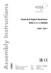
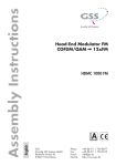
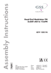
Head-End 5 to 1 Multiplexer
5xASI/IP to 1xASI/MPTS
KLASSE
HADA 5100
English
CLASS
GSS
Grundig SAT Systems GmbH
Beuthener Strasse 43
D-90471 Nuremberg
Phone:
Fax:
E-mail:
Internet:
+49 (0) 911 / 703 8877
+49 (0) 911 / 703 9210
[email protected]
http://www.gss.de
Contents
1 Safety regulations and notes............................................................................... 4
2 General information........................................................................................... 5
2.1 Packing contents.................................................................................... 5
2.2 Meaning of the symbols used.................................................................. 5
2.3 Technical data....................................................................................... 5
2.4 Description........................................................................................... 6
2.5 Software query...................................................................................... 7
3 Assembly........................................................................................................... 8
3.1 Installing the cassette.............................................................................. 8
3.2 EMC regulations.................................................................................... 9
3.3 Cassette overview................................................................................ 10
3.4 Connecting the cassette........................................................................ 10
4 The control panel at a glance............................................................................ 11
4.1 Menu items......................................................................................... 11
4.2 Control panel...................................................................................... 11
5 Programming................................................................................................... 12
5.1 Programming procedure............................................................................12
5.2 Programming the cassette..................................................................... 15
Selecting the cassette........................................................................ 15
Ethernet parameters.......................................................................... 16
Hardware IP address........................................................................ 16
Address range................................................................................. 17
Address of the gateway.................................................................... 17
UDP port......................................................................................... 18
Output parameters............................................................................ 18
ASI transmission rate......................................................................... 19
ASI options........................................................................................ 19
Output IP address............................................................................. 20
Switching the IP address off or on....................................................... 21
Transmission protocol........................................................................ 21
Port number..................................................................................... 21
Quantity of data packets................................................................... 22
Forward error correction................................................................... 22
Transmission channel........................................................................ 22
Input parameters.............................................................................. 23
Signal source................................................................................... 23
Switching the IP address off or on....................................................... 24
Transmission protocol........................................................................ 24
Port number..................................................................................... 24
Input IP addresses............................................................................. 25
- 2 -
HADA 5100
Station filter..................................................................................... 25
Manually selection............................................................................ 26
Hint for the Service IDs...................................................................... 27
Transport stream / ORGNET-ID.......................................................... 28
Output data rate............................................................................... 28
Factory reset.................................................................................... 29
Saving settings................................................................................. 29
6 Final procedures............................................................................................... 30
- 3 -
HADA 5100
1
Safety regulations and notes
• Assembly, installation and servicing should be carried out by authorised
electricians.
• Switch off the operating voltage of the system before beginning with assembly or service work or pull out the mains plug.
• Do not perform installation and service work during thunderstorms.
• Install the system so it will not be able to vibrate…
- in a dust-free, dry environment
- in such a manner that it is protected from moisture, fumes, splashing water and dampness
- somewhere protected from direct sunlight
- not within the immediate vicinity of heat sources
- in an ambient temperature of 0 °C to +50 °C. In case of the formation of
condensation wait until the system is completely dried.
• Ensure that the head-end station is adequately ventilated. Do not cover the
ventilation slots.
• Beware of short circuits
• No liability is accepted for any damage caused by faulty connections or
inappropriate handling.
• Observe the relevant standards, regulations and guidelines on the installation and operation of antenna systems.
• The standards IEC/EN/DIN EN 50083 and IEC/EN/DIN EN 60728 must
be observed.
• For further information please read the assembly instructions for the headend station used.
• Test the software versions of the head-end station and the cassette and
update them if necessary. The current software versions can be found at
”www.gss.de”.
Take action to prevent static discharge when working on the device!
Electronic devices should never be disposed of in the household rubbish. In
accordance with directive 2002/96/EC of the European Parliament and the
European Council from January 27, 2003 which addresses old electronic and
electrical devices, such devices must be disposed of at a designated collection
facility. At the end of its service life, please take your device to one of these
public collection facilities for proper disposal.
- 4 -
HADA 5100
2
General information
2.1
Packing contents
1 Cassette HADA 5100
6 BNC cable
2.2
Meaning of the symbols used
1 LAN cable
1 Brief assembly instructions
Important note
—> General note
•
2.3
Technical data
The devices meet the following EU directives:
2006/95/EC, 2004/108/EC
The product fulfils the guidelines and standards for CE labelling.
Unless otherwise noted all values are specified as “typical”.
LAN interface
Standard:..............................................................10-BASE-T, IEEE 802.3i
100-BASE-TX, IEEE 802.3u
1000-BASE-X , IEEE 802.3z
Data rate:...............................................................................≤ 180 MBit
Protocols:........................................................... UDP (User Data Protocol),
RTP (Real-Time Transport Protocol)
ASI interfaces
Standard:......................................................................DIN EN 50083-9
Format:.................................................................MPEG ISO IEC 13818-1
User data rate:.................................................................. 2 … 90 Mbit/s
Impedance:..................................................................................... 75 Ω
Max. data rate:.......................................................................180 MBit/s
Level (input / output):.......................................................800 mVPP ± 10%
Return loss (input):................................................ > 17 dB (5 … 270 MHz)
Performing works
- 5 -
HADA 5100
Connections
LAN:................................................................................. 1 RJ 45 socket
ASI inputs:............................................................... 5 BNC sockets, 75 Ω
ASI output:.................................................................1 BNC socket, 75 Ω
Connection strip (10-pin):....................for supply voltages and control circuits
RS 232 socket:...................................... serial interface for software update
2.4
Description
The cassette is a 5 to 1 multiplexer. It converts 5 ASI/SPTS/MPTS input channels
into one ASI/MPTS output channel. Each input channel has (selectively) one ASI
input (ASI – Asynchronous Serial Interface according to DIN EN 50083-9) and
one LAN interface (1 input IP address).
The fed in transport streams can be edited individually and will be combined into
one transport stream in the TPS module. This transport stream is emitted at the ASI
output or the LAN interface (1 output IP address). For operating the cassette in a
LAN network it can be assigned its own hardware IP address.
—> Two IP address ranges are used:
"Hardware" IP addresses (menu ETHERNET), which are used to
connect the cassettes in the network (e.g. 192.168.0.x).
"IPTV" IP addresses (menus OUT-IP, IP-INPUT), which are used to send
and receive the IPTV channels (multicast range e.g. 227.40.50.x).
Principle signal path:
LAN1: 227.40.50.1
ASI input 1
LAN 2: 227.40.50.2
ASI input 2
LAN 6: 227.40.50.6
LAN 3: 227.40.50.3
ASI input 3
TPS
ASI output
LAN 4: 227.40.50.4
ASI input 4
LAN 5: 227.40.50.5
ASI input 5
- 6 -
HADA 5100
The cassette is controlled with the head-end station control unit.
The LEDs for the LAN interface show whether a network connection exists and
whether a data transfer is in progress.
When the head-end station is switched on, the two-line LC display shows the
software version of the control unit.
To operate this cassette the software version of the control unit must be “V 42”
or higher. You can find the current operating software for the control unit and
the cassette, the software “BE-Flash” and the current assembly instructions on
the website “www.gss.de”.
The cassette is designed for use in the following head-end stations:
STC 1200, STC 816 and PST 19-1.
Five LEDs (6,
nal is present:
8, 0, @, $) indicate by their colour whether an input sigLED colour
Green
Red
123 4
56 78 90 !@ #$
%
^
2.5
Software query
Control unit
If necessary, you can activate the indication of the software version of the
control unit manually:
• Press any two keys on the control unit of the head-end station simultaneously until the display goes dark and the software version, e.g. “V 42” appears.
Indication
Signal present
no Signal
Cassette
After activating the cassette the software version of the cassette is displayed
(see page 15).
- 7 -
HADA 5100
3
Assembly
3.1
Installing the cassette
– Ensure the head-end station is mounted so it will not be able to vibrate.
Avoid, for example, mounting the head-end station onto a lift shaft or any
other wall or floor construction that vibrates in a similar way.
– Before installing or changing a cassette unplug the power cable from the
mains power socket.
• Remove the fastening screws 1 of an unoccupied slot from the bracket of
the head-end station.
• Insert the cassette in this slot and push it into the housing.
• Align the cassette and apply slight pressure to connect it to the connections
of the board and the HF bus bar.
• Fasten the cassette with the screws 1.
1
ACHTUNG!
Vor dem Cassettenwechsel
unbedingt Netzstecker ziehen!
CASSETTE
CASSETTE
CASSETTE
CASSETTE
CASSETTE
CASSETTE
CASSETTE
CASSETTE
CASSETTE
CASSETTE
CASSETTE
CASSETTE
0°
MESSAUSGANG
KLASSE
CAUTION!
Before changing cassettes remove
mains plug!
A
CLASS
1
- 8 -
HADA 5100
3.2 EMC regulations
KLASSE
CLASS
To comply with the current EMC regulations, it is necessary to connect the lines
leading in and out of the head-end station using cable terminals.
When mounting the cassette in a head-end station which is installed in a 19”
cabinet, make sure the connections leading in and out for the 19” cabinet are
made using cable terminals.
The attenuation of shielding of the connection lines for ASI and antenna must
meet the requirements for “Class A”.
• Insert the required number of cable terminals in the openings provided in
the head-end station or in the 19” cabinet.
Tighten the nuts on the cable terminals until the teeth on the lock washer have
penetrated the exterior coating and a good connection is made between the housing and cable terminals.
- 9 -
HADA 5100
3.3
Cassette overview
123 4
1
2
3
4
5
6
7
8
9
0
!
@
#
$
%
56 78 90 !@ #$
%
^
Status LED of the LAN interface (data transfer)
LAN socket
Status LED of the LAN interface (network connection)
ASI output
ASI input 5
Status LED ASI input 5
ASI input 4
Status LED ASI input 4
ASI input 3
Status LED ASI input 3
ASI input 2
Status LED ASI input 2
ASI input 1
Status LED ASI input 1
D-SUB socket “RS 232“
—> The operating software of the cassette can be updated via the 9-pin
D-SUB socket “RS 232” using a PC or notebook and the software
“BE-Flash”. You can find the current operating software on the website "www.gss.de".
^
3.4
Connecting the cassette
• Connect the LAN socket 2.
• Connect the ASI inputs 5, 7,
peripheral ASI devices.
Type label + MAC address
9, !, # and the ASI output 4 to the
- 10 -
HADA 5100
4
The control panel at a glance
4.1
Menu items
Programme the cassette using the buttons on the control unit of the head-end
station. The two-line display of the control unit then shows the menus.
The parameters and functions to be set are underlined.
Use the
key to select the following main menu items:
– Ethernet parameter
– Output parameter
– Input parameter
– Transport stream and ORGNET-ID
– Displaying the data rate
– Factory reset
4.2
Control panel
The key pad on the head-end station is used to scroll through the menus:
V42
please wait . . .
scrolls forward through the menus.
select parameters in the menus.
set values, initiate actions.
selects sub-menus.
scrolls backward through the menus.
saves all entries.
BE-Remote
- 11 -
HADA 5100
5
Programming
5.1
Programming procedure
Ein / On
BE–Remote
V 42
please wait …
t > 10 s
Box 1
……
………
……
+
Box 4
Bx 1A
TWIN-SAT
Böx 4
TWIN-SAT
Box 5
……
C5-12,S3-24
C07
C5-12,S3-24
C07
………
……
TS-MUX
V1
0.128 – – –
A
B
Bx 4
stat
ETHERNET
=>
Options
▶
Bx 4
IP-ADDR
192.168.
0.128
Page 14
◀/▶
stat / DHCP
Bx 4
IP-MASK
255.255.255.
Bx 4
IP-GATEWAY
192.168.
Bx 4
0.
◀/▶
0
◀/▶
1
UDP-PORT
◀/▶
60000
0 … 65535
nur bei Auswahl "ASI"
only with selection "ASI"
Bx 4
ASI
OUTPUT
=>
▶
ASI RATE
◀/▶
108000 KBits
ASI/LAN
ASI OPTION
188
pos. cont.
- 12 -
◀ / ▶ 188 / 204
positiv / negativ,
positive / negative
HADA
5100
kontinuierlich
/ burst,
continuous / burst
ASI/LAN
ASI OPTION
188
◀ / ▶ 188 / 204
positiv / negativ,
positive / negative
kontinuierlich / burst,
continuous / burst
pos. cont.
nur bei Auswahl "LAN"
only with selection "LAN"
OUT-IP
227.
40.
50.
6
MODE / PORT
on
1234
UDP
PKTS / FEC
7
◀/▶
◀ / ▶ on / off
UDP / RTP,
0 … 65535
◀ / ▶ off / 10/9 … 20/19
Annex A / Annex B
off
1…7
1 …5
Bx 4
INPUT
1 LAN
OK =>
▶
IN 1
INPUT
LAN
ASI / LAN
INFO:
ASI/LAN
– – –/OK
nur bei Auswahl "LAN"
only with selection "LAN"
IN 1
on
MODE / PORT
UDP
IN 1
227.
1234
IP-INPUT
40.
IN 1
50.
1
◀ / ▶ on / off
UDP / RTP,
0 … 65535
◀/▶
FILTER
first / all /
cascaded / manual
all
IN 1
TV ± 001/016
Das Erste
- 13 -
nur bei Auswahl "manual"
only with selection "manual"
◀/▶
HADA 5100
first / all /
cascaded / manual
all
◀/▶
Das Erste
◀/▶
Bx 4
nur bei Auswahl "manual"
only with selection "manual"
TV ± 001/016
IN 1
TS/ONID
0x0001,0100
Bx 4
DATARATE
087/180
Page 12
Bx 4
FACTORY
Defaults
=>
▶
Bx 4
FACTORY
STORE
=> M
A
M
B
Page 12
- 14 -
HADA 5100
5.2
Programming the cassette
—> Pressing the
button for longer than 2 seconds cancels the
programming procedure. This takes you back to the program item
“Selecting the cassette” from any menu. Any entries that have not
been saved are reset to the previous settings.
—> Entries in the menus can be saved by pressing the
key. You are
taken back to the “Selecting the cassette” menu item.
—> Pressing the
button returns to the previous menus.
• Switch on the head-end station
Ein / On
BE–Remote
V 42
please wait …
t > 10 s
—> The display shows the software version (e.g. V 42)
—> The processor reads the cassettes‘ data (approx. 10 seconds).
Selecting the cassette
Box 1
……
………
……
+
Box 4
V1
Bx 1A
TWIN-SAT
Böx 4
TWIN-SAT
Box 5
……
C5-12,S3-24
C07
C5-12,S3-24
C07
………
……
TS-MUX
0.128 – – –
• Select the cassette you want to program (e.g. Box 4) by repeatedly pressing
the button
if necessary.
—> The display shows e.g. the menu"Box 4 TS-MUX":
"Box 4"
stands for slot 4,
"TS-MUX"
type of cassette
"V 1"
software version of the cassette
192.168."0.128"
hardware IP address of the cassette
- 15 -
HADA 5100
• Press the
button.
—> The "Ethernet parameters" – "ETHERNET" main menu is activated.
Ethernet parameters
In this menu you specify whether the Ethernet parameters for the cassette are
entered automatically by a connected server (“DHCP”), or whether you want
to enter them manually (“stat”).
—> To assign the cassette uniquely, each IPTV cassette must be allocated
its own IP address.
Bx 4
stat
ETHERNET
=>
Options
—> To skip the setting of the Ethernet parameter press the
button. The "Output parameters" – "OUTPUT" main menu is activated
(page 18).
• Press the
buttons to select manual setting (”stat”) or automatic setting
(”DHCP”) of the Ethernet parameters.
• Press the
button to activate the setting options (”Options”).
—> The “Hardware IP address” – “IP-ADDR” sub menu is activated.
Hardware IP address
To operate the cassette in a network, an IP address must be assigned to each
IPTV cassette. If a manually setting of the Ethernet parameters is selected, set
the IP address of the cassette in this menu. If “DHCP” is selected, the “IP-ADDR”,
“IP-MASK” and “IP-GATEWAY” sub-menus display the parameters that were assigned automatically by a connected DHCP server, e.g. “192.168.   0.128*”.
The star “ * ” in the display means that the data is provided by a DHCP server.
If no server is connected, “   0.   0.   0.   0” appears in the corresponding
menu.
Bx 4
IP-ADDR
192.168.
0.128
- 16 -
HADA 5100
• Use the
buttons to place the cursor under the digit of the IP address
displayed to be set and use
to set the IP address wished.
• Press the
button.
—> The “Address range” – “IP-MASK” sub menu is activated.
Address range
In this menu you define the address range for the cassettes connected to the
LAN network.
Bx 4
IP-MASK
255.255.255.
0
• Use the
buttons to place the cursor under the digit of the IP mask
displayed to be set and use
to set the IP mask wished.
• Press the
button.
—> The “Address of the gateway” – “IP-GATEWAY” sub menu is activated.
Address of the gateway
The address of a gateway (server/router) can be set in this menu. If no gateway is used you can skip this setting.
Bx 4
IP-GATEWAY
192.168.
0.
1
• Use the
buttons to place the cursor under the digit of the IP address
displayed to be set and use
to set the IP address wished.
• Press the
button.
—> The “UDP port” – “UDP-PORT” sub menu is activated.
- 17 -
HADA 5100
UDP port
The UDP port setting is required if the cassette shall be controlled via remote
access and the standard port 60000 can not be used.
Bx 4
UDP-PORT
60000
• Use the
buttons to place the cursor under the digit of the port number
displayed to be set and use
to set the port number wished (”0” …
”65535”).
• Press the
button.
—> The "Output parameters" – "OUTPUT" main menu is activated.
Output parameters
In this menu you select whether you whish to output the output transport stream
via the ASI output or the LAN. In addition you can set the output parameters
in the submenus.
Bx 4
ASI
• Use the
OUTPUT
Bx 4
OUTPUT
=>
LAN
=>
buttons to select the output wished ("ASI" or "LAN").
—> To skip the settings of the output parameters press the
button. The "Input parameters" – "INPUT" main menu is activated
(page 23).
• Press the
button.
—> If "ASI" is selected, the "ASI transmission rate" – "ASI RATE" submenu is activated.
—> If "LAN" is selected, the "Output IP address" – "OUT-IP" submenu is
activated (page 20).
- 18 -
HADA 5100
ASI transmission rate
In this menu you set the output transmission rate for the ASI component connected. For this setting please take the required information from the documentation (technical data) of the ASI component to be connected.
ASI RATE
108000 KBits
• Use the
buttons to place the cursor under the digits to be set for the
transmission rate then use the
buttons to set the transmission rate
wished.
• Press the
button.
—> The “ASI options” – “ASI OPTION” sub menu is activated.
ASI options
In this menu you define the size of the data packets, their polarity and the type
of transmission.
For this setting please take the required information from the documentation
(technical data) of the ASI component to be connected.
ASI OPTION
188
pos. cont.
• Press the
bits).
buttons to set the size of the data packets (“188” or “204”
• If the polarity of the data to be transmitted has to be changed, press the
buttons to place the cursor under “pos.” (positive – standard) and using the
buttons set to “neg.” (negative).
• To change the type of transmission press the
buttons to position the
cursor under “cont.” (continuous – standard) and using the
set to
“burst”.
—> Setting “cont.”
The data packets of the user data are collected to a great data
packet in the transport stream.
- 19 -
HADA 5100
—> Setting “burst”
The data packets of the user data are spaced out evenly in the transport stream.
• Press the
button.
—> You will be returned to the “Output parameters” – “OUTPUT” main menu
(page 18).
Output IP address
In this menu you set the IP address for the IP output.
OUT-IP
227.
40.
50.
6
—> Use an IP address of the multicast range (e.g. 227.40.50.x).
• Press the
buttons to position the cursor under the digit of the IP address to be set.
• Using the
buttons set the IP address wished.
• Press the
button.
—> The “Switching the IP address off or on, transmission protocol, port
number” – “MODE / PORT” submenu is activated.
- 20 -
HADA 5100
Switching the IP address off or on
Transmission protocol
Port number
In this menu you can switch off the IP address displayed, and define the transmission protocol and the port number.
MODE / PORT
on
UDP
1234
Switching the IP address off or on
• Press the
buttons to switch off (”off”) or (“on”) the IP address and the
service referred.
Selecting the transmission protocol
• Press the
button to position the cursor under ”UDP”.
• Using the
buttons to select the transmission protocol wished:
—> "UDP"– The User Datagram Protocol is for the connectionless transmission of data without acknowledgement from the receiver.
"RTP" – The Real-time Transport Protocol additional transmits time informations for runtime error correction at receiver side.
Setting the port number
• Press the
button to position the cursor under the port number e.g.
”  1234”.
• Use the
buttons to position the cursor under the digit of the port
number displayed to be set.
• Using the
buttons set the port number wished.
• Press the
button.
—> The “Quantity of data packets, Forward error correction, Transmission channel” – “PKTS / FEC” submenu is activated.
- 21 -
HADA 5100
Quantity of data packets
Forward error correction
Transmission channel
In this menu you set the quantity of the data packets to be transmitted, the
forward error correction FEC and the transmission channel. If the forward error correction is used additional redundant data are transmitted, so that the
addressee can correct transmission errors.
PKTS / FEC
7
off
Defining the quantity of data packets
• Using the
buttons define the quantity of MPEG data packets in one IP
data packet (”1” … ”7”).
—> Setting ”7” results the smallest overhead.
Setting the forward error correction
• Press the
button to position the cursor under ”off” .
—> In position ”off” the forward error correction (FEC) is switched off.
• Using the
”20/19”).
buttons set the value of the FEC wished (”off, 10/9” …
PKTS / FEC
7
10/09 AnnexB
Setting the transmission channel
• Press the
button to position the cursor under ”Annex…”.
• Use the
buttons to set the transmission channel wished (”AnnexA” /
”AnnexB”).
• Press the
button.
—> You will be returned to the “Output parameters” – “OUTPUT” main menu
(page 18).
• Press the
button.
—> The "Input parameters" – "INPUT" main menu is activated.
- 22 -
HADA 5100
Input parameters
In this menu you select the input, for which you would like to set the input parameters in the submenus.
Bx 4
INPUT
1 LAN
OK =>
—> The indications "LAN" and "OK" serve for information:
LAN - LAN is already set for input 1.
OK - input signal is present at input 1.
• Use the
buttons to select the input ("1" … "5"), for which you would
like to set the input parameters.
—> To skip the settings of the input parameters press the
button. The "Transport stream and ORGNET-ID" – "TS/ONID" main
menu is activated (page 27).
• Press the
button.
—> The "Signal source" – "IN x
INPUT" submenu is activated.
Signal source
In this menu you select the signal source wished for the selected input.
IN 1
LAN
• Use the
INPUT
IN 2
INPUT
ASI
buttons to select the signal source wished ("LAN" or "ASI").
—> If "ASI" is selected, the "Station filter" – "IN x Filter" submenu is
activated (page 25).
—> If "LAN" is selected, the "Switching the IP address off or on, Transmission protocol, Port number" – "IN x MODE / PORT" submenu is
activated.
- 23 -
HADA 5100
Switching the IP address off or on
Transmission protocol
Port number
In this menu you can switch off the IP address displayed, and define the transmission protocol and the port number.
MODE / PORT
on
UDP
1234
Switching the IP address off or on
• Press the
buttons to switch off (”off”) or (“on”) the IP address and the
service referred.
Selecting the transmission protocol
• Press the
button to position the cursor under ”UDP”.
• Using the
buttons to select the transmission protocol wished:
—> "UDP" – The User Datagram Protocol is for the connectionless transmission of data without acknowledgement from the receiver.
"RTP" – The Real-time Transport Protocol additional transmits time informations for runtime error correction at receiver side.
Setting the port number
• Press the
button to position the cursor under the port number e.g.
”  1234”.
• Use the
buttons to position the cursor under the digit of the port
number displayed to be set.
• Using the
buttons set the port number wished.
• Press the
button.
—> The "Input IP addresses" – "IN x IP-INPUT" submenu is activated.
- 24 -
HADA 5100
Input IP addresses
In this menu you set the IP address for the IP input selected.
IN 1
227.
IP-INPUT
40.
50.
1
—> Use an IP address of the multicast range (e.g. 227.40.50.x).
• Press the
buttons to position the cursor under the digit of the IP address to be set.
• Using the
buttons set the IP address wished.
• Press the
button.
—> The "Station filter" – "IN x Filter" submenu is activated.
Station filter
In this menu you select the stations (services) of the input transport stream
which shall be used.
IN 1
FILTER
all
• Use the
buttons to select the option wished.
—> "all" - all stations are used.
"cascaded" - setting for the "downstreamed" HADA 5100
when using several HADA 5100 cascaded – observe the following
hints about the service IDs (SIDs) as well as chapter "cascading"
(page 31).
"first" - only the first station of the transport stream is used.
"manual" - the additional submenu "Manually selection" will be
displayed next.
- 25 -
HADA 5100
Hints about the service IDs
Service IDs (SID)
New SIDs will be assigned to the selected services.
At settings "all", "first" und "manual" the assignment of the SIDs is done
"dynamically" according to the following scheme :
Input 1 - services 1 … 64—> SIDs 101 … 164
Input 2 - services 1 … 64—> SIDs 201 … 264
Input 3 - services 1 … 64—> SIDs 301 … 364
Input 4 - services 1 … 64—> SIDs 401 … 464
Input 5 - services 1 … 64—> SIDs 501 … 564
—> If more than 64 services per input are selected, this "overflow" is
assigned from SID 601 upwards.
—> At setting "cascaded" the assignment of the SIDs is done "statically".
Therefore an example is shown in chapter "cascading" page 31.
• Press the
button.
—> Is "all", "cascaded" or "first" selected, you will be returned to the
“Input parameters” – “INPUT” main menu (page 23).
—> Is "manual" selected, The "Manually selection" – "IN x xxx/yyy"
submenu is activated.
- 26 -
HADA 5100
Manually selection
In this menu you select the stations (services) of the input transport stream
which shall be used.
IN 1
TV ± 001/016
Das Erste
—> All stations (Services) of the input transport stream will be read, and
then displayed with name and station type.
—> If no station is found, the following message will appear in the display:
“FILTER no Service”.
In this case, check the configuration of the antenna system and headend station, as well as the previously adjusted settings for the cassette
and the components connected to the ASI/LAN input.
—> The display shows e.g.:
IN 1 TV + 001/016
Das Erste
Meaning of the indicators in the example:
"IN 1"
Number of the selected input
"TV"
Station type "Television"
"+"
The currently selected station is activated.
"001/016"
The 1st of 10 stations is being displayed.
"Das Erste"
Station name
Further possible terms displayed:
"RA"
Radio channel type
For radio stations, the background of the screen of
the connected TV or test receiver is darkened.
"—"
The currently selected station is deactivated.
"HD"
HD reception
—> If a service number (e.g. “131”) appears instead of “TV” or “RA”,
this indicates that an unnamed station or an undefined data stream
is being received.
• Use the
“ – ”).
buttons to call up the stations in sequential order, then use
to activate (indicated by “ + ”) or to deactivate them (indicated by
- 27 -
HADA 5100
If no station is found, the display shows "– – –" instead of the station name. In
this case, check the previously adjusted settings for the cassette and the components connected to the ASI/LAN input.
• Press the
button.
—> You will be returned to the “Input parameters” – “INPUT” main menu
(page 23).
—> If necessary set further inputs.
• Press the
button.
—> The “Transport stream / ORGNET-ID” – “TS/ONID” main menu is
activated.
- 28 -
HADA 5100
Transport stream / ORGNET-ID
If the stations (services) of several transponders are merged to one transport
stream, a new identification (ORGNET-ID) must be allocated to the transport
stream, to realise the channel search of the settop boxes connected without
mistakes.
Bx 4
TS/ONID
0x0001,0100
• Use the
buttons to position the cursor under the digit of the hexadecimal number to be set.
• Press
to set the respective digit of the hexadecimal number.
• Repeat the procedure by the quantity of the digits to be set.
• Press the
button.
—> The "Output data rate" – "DATARATE" main menu is activated.
Output data rate
In this menu the current output data rate is displayed.
Bx 4
DATARATE
087/180
—> "087" - current data rate.
"180" - maximum data rate
—> The maximum Data rate depends on the used/available output:
– 1 GBit LAN - 180 MBit
– 100 MBit LAN - 80 MBit
– ASI - ASI RATE setting (page 19)
• Press the
button.
—> The "Factory reset" – "FACTORY" main menu is activated.
- 29 -
HADA 5100
Factory reset
In this menu you can reset all settings to the factory defaults.
Bx 4
FACTORY
Defaults
=>
▶
Bx 4
FACTORY
STORE
=> M
A
M
B
• Press the
button.
—> The submenu “FACTORY STORE” is invoked.
—> By pressing the
button, you will be returned to the menu
item “Ethernet parameters” – “ETHERNET” without invoking the factory defaults (page 16).
• Press the
button.
—> The factory defaults are saved. The display shows “STORE”
—> Back to “Selecting the cassette” (page 15).
—> By pressing the
button, you will be returned to the menu
item “Ethernet parameters” – “ETHERNET” without invoking the factory defaults (page 16).
Saving settings
• Press the
button.
—> Back to “Selecting the cassette” (page 24).
—> The settings are saved.
- 30 -
HADA 5100
Cascading
If several HADA 5100 are cascaded, at the "downstreamed" cassette (cassette
6 of the example) the station filter (page 25) must be set to "cascaded".
Cascading, for example, is used to combine many transport streams each
containing one service to one transport stream.
Service
01…05
SID101,201,301,401,501
SID101,201,301,401,501
SID101,201,301,401,501
SID101,201,301,401,501
Service 21…25
SID101,201,301,401,501
Service 16…20
Service 06…10
06
07
08
09
10
"downstreamed"
Service 11…15
Service
Service
Service
Service
Service
01
02
03
04
05
Cassette 2
Service
Service
Service
Service
Service
Cassette 1
Example:
"upstreamed"
Cassette 6
Service 01…25
SID
SID
SID
SID
SID
101…105
201…205
301…305
401…405
501…505
Cassette 3
Cassette 4
Cassette 5
At setting "cascaded" the assignment of the SIDs is done "statically", so that
the SIDs of the services at the output of the "downstreamed" cassette (6) will
not change, if the input signal of one input of the "upstreamed" cassettes (1…5)
is discontinued.
"Static" SID assignment at setting "cascaded"
(for cassette 6 of the example):
Input
300
400
Input SID
SID at the output
101
101
201
301
401
201
102
202
302
402
301
103
203
303
403
401
104
204
304
404
501
105
205
305
405
Example: SID 301 at input 2 —> SID 203 at the output
100
200
- 31 -
500
501
502
503
504
505
HADA 5100
Table for "static" SID assignment at station filter setting "cascaded"
100
Input SID
101
102
103
104
105
106
201
202
203
204
205
206
301
302
303
304
305
306
401
402
403
404
405
406
501
502
503
504
505
506
101
111
121
131
141
151
102
112
122
132
142
152
103
113
123
133
143
153
104
114
124
134
144
154
105
115
125
135
145
155
Input
200 300 400
SID at the output
201 301 401
211 311 411
221 321 421
231 331 431
241 341 441
251 351 451
202 302 402
212 312 412
222 322 422
232 332 432
242 342 442
252 352 452
203 303 403
213 313 413
223 323 423
233 333 433
243 343 443
253 353 453
204 304 404
214 314 414
224 324 424
234 334 434
244 344 444
254 354 454
205 305 405
215 315 415
225 325 425
235 335 435
245 345 445
255 355 455
- 32 -
500
501
511
521
531
541
551
502
512
522
532
542
552
503
513
523
533
543
553
504
514
524
534
544
554
505
515
525
535
545
555
If more than one services
are present at one input of
the upstreamed cassettes
(cassettes 1…5 of the example), in the downstreamed
cassette (cassette 6 of the
example) the SIDs will be
assigned "statically" according to the table beside.
According to this table up
to 6 services per input (cassettes 1…5) can be processed.
Example:
If at input 2 of cassette 2
two services are present,
SID 202 is assigned to the
2nd service at the output of
cassette 2 (according to the
"dynamic" scheme at page
26). This SID 202 is present
at input 2 of cassette 6.
According to the table beside the SID is transformed
in cassette 6 to SID 212.
From the 7th service at one
input of the cassettes 1…5
on the SIDs will be transformed "dynamically" in
Cassette 6.
HADA 5100
6
Final procedures
After installing the head-end station, upgrading accessories or installing cassettes it is necessary to tighten all cable connections, cable terminals and cover
screws in order to maintain compliance with current EMC regulations securely.
• Securely tighten the cable bolted connections using an appropriate openended spanner.
• Mount the front cover (see assembly instructions of the head-end station).
- 33 -
HADA 5100
Service:
Phone:
Fax:
Email:
+49 (0) 911 / 703 2221
+49 (0) 911 / 703 2326
[email protected]
Alterations reserved. Technical data E. & O.E.
© by GSS GmbH
V1/09062010