1
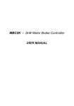
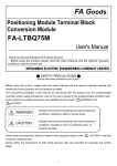
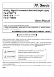
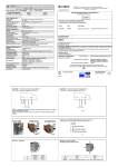
USER MANUAL
EN
KIT AUDIO DOOR PHONE basic
1 family
Harry Johnston
Call from the Outdoor panel’s key;
Full duplex hands-free audio communication;
Command of the access gate/door opening from the interior Terminal;
Audio monitoring of the entrance of the property, by the inhabitant;
Optional 1 audio Terminal in parallel;
UTP CAT 5e (AWG 24) cable required.
Harry Johnston
Outdoor panel
1 pc.
238 × 144 × 53 mm
Terminal
1 pc.
170 × 96 × 30 mm
Audio communication
Full-duplex
Data communication
Digital
Supply tension of the system
(supply of the control unit)
Maximum power expenditure from
the 230 V AC network
Supply control unit
1 pc.
130 × 141 × 73 mm
0,4 A AC
2.1 Technical features of the outdoor audio panel
Supply tension
12,0 ... 14,3 V DC (stabilized)
Keyboard
TOUCH type, permanently backlit
Display of the inhabitant's name
Backlit name space
Case
Aluminum profile painted in electrostatic field;
Secured glass screen, 8 mm thick
Mounting
Flush
Casing protection level (IP)
IP44
Operating temperature range
Transport and storage temperature
range
Dimensions
- 30° C ... + 60°C
238 x 144 x 53 mm
Weight
1,3 kg
- 33° C ... + 55° C
02
EN
2.2 Technical features of the audio Terminal
Supply tension
12,0 ... 14,3 V DC (stabilized)
Keyboard
TOUCH type, 4 keys, backlit on touch
Permanent RED signaling of the VOLUME key if the
Terminal is turned off.
Audio adjustments
Case
Audio communication volume: MAXIMUM LEVEL –
MEDIUM LEVEL – TURNED OFF
ABS
Glass screen, 3 mm thick
Mounting
Surface
Casing protection level (IP)
IP31
Operating temperature range
0°C ... + 45°C
Range of transport and storage
temperatures
- 33°C ... + 55°C
Dimensions
171 x 96 x 30 mm
Weight
0,4 kg
2.3 Technical features of the Supply control unit
Supply tension
Generated power tensions/
power capability
230V±10%/50Hz
+14V – GND : +14V DC (stabilised) / 2A DC
+Uv
– GND : +14V DC (stabilised) / 0,5A DC
Vcam – GND : +12V DC (stabilised) / 0.4 A DC
Case
Fireproof ABS
Mounting
On DIN rail: TH 35 x 15 or 35 x 7,5 in compliance
with DIN46277-3, EN50022, IEC60715
Surface: with A3,5 x 32 plastic screws and
ø 6 mm pins
Casing protection level (IP)
IP31
Operating temperature range
0°C ... + 45°C
Range of transport and storage
temperatures
- 33°C ... + 55°C
Dimensions
130 x 141 x 73 mm
Weight
0,4 kg
03
All additional products are sold separately.
OUTDOOR
INDOOR
3/
ACC
12V/7Ah
Accumulator
(Optional)
2/
(Optional)
Electromagnetic
lock DC / AC
3/
4/
3/ 230 VAC
Supply control unit
Panel
Terminal
Additional terminals in parallel (optional)
3
3
From the supply
control unit
/
/
4
4.1 Recommended cables
Outdoor panel
Supply control unit
Audio Terminal
UTP CAT5e (AWG24) cable for distances of maximum 70 m between the Outdoor panel and
the Supply control unit and 250m between the Outdoor panel and the audio Terminal.
For distances greater than 250 m, please request additional information from the producer.
Supply control unit
Electromagnetic lock (optional)
Flexible, multistrand cable, (Cu) 2 or 3 x 0,75 mm² for distances of maximum 50 m or
(Cu) 2 or 3 x 1 mm² for distances of maximum 100 m.
Supply control unit
230 V AC network
Flexible, multistrand cable, (Cu) 3 x 0,75 mm²
04
EN
4.2 Safety instructions for installation
è
è
è
è
è
è
è
è
è
è
è
AT TENTION! The installation, the connection to the 230V/50 Hz network and
the maintenance of the Supply control unit Supply control unit will only be
carried out by authorized personnel!
The installation of the Supply control unit is recommended to be made within
an electrical panel.
AT TENTION! DO NOT UNFASTEN THE FRONT LID! DANGER OF
ELECTRIC SHOCK!
Only the protection lids of the connections can be unfastened.
AT TENTION! It is mandatory for the supply of the Supply control unit from
the 230 V/50Hz network to be made through two automatic fuses of 10 A (on
phase and null). The connection of the F and N terminals of the Supply control
unit will be made through two isolated (Cu) wires, with a section of 0,75mm².
AT TENTION! During the installation, connection of the Supply control unit at
the 230 V/50Hz network and during service, the safety fuses from the panel
must be opened (POWER OFF).
The connection of the (Cu) 0,75mm² grounding wire between the grounding
terminal of the electrical panel
and the grounding terminal of the Supply
control unit
is MANDATORY.
IMPORTANT! Before connecting the Supply control unit's supply fuses, check
the precision of the connections in the system. Check both visually, and by
measurement with an ohmmeter.
IMPORTANT! Install the protection lids of the Supply control unit's
connections before connecting the 2 supply fuses (230V/50Hz).
PAY AT TENTION to the polarity of the terminals when connecting them to
the Supply control unit of a buffer accumulator (max. 7 Ah). The inversion of
the terminals leads to the failure of the accumulator. The installation and
connection of the accumulator will be carried out by authorized personnel.
DO NOT TOUCH the wires exiting from the connectors and the terminals of
the control supply unit. Disconnect the fuses (10 A) from the supply's phase
and null of the Supply control unit.
AT TENTION! Do not supply components of the installation separately
(Outdoor panel, connection boxes, Terminals etc.) at tensions higher than 15V
DC or directly from the network (230V/50Hz). DANGER OF ELECTRIC
SHOCK and of the door phone system's destruction.
Wall mounting
DIN rail mounting
1
2
DIN rail
3
Retainer
A3,5 x 32 screw (2 pcs.)
Protection lid (2 pcs.)
B2,9 x 13 screw (4 pcs.)
05
73,0
42,8
35,5
130,0
117,5
35,5
46,0
76,0
140,7
51,0
The accumulator will be connected to the terminals of the power supply, after the
commissioning of the system.
4.4 Installation of the audio terminal
A3,5 × 35(32) screw
(4 pcs.)
155 cm
1
2
The terminal will be placed at 155 cm
height (recommended height)
Cable length
(from the wall)
29,5
21
60,0
95,7
113,5
37,5
171,5
20,5
96,5
≈18 cm
48,2
06
EN
4.5 Installation of the Outdoor panel
The Outdoor panel is installed at the entrance of the property or building, on the body closest
to the access door, at a height of approx. 1.7 m (upper part) from the ground, protected from
rain and sunrays.
Before starting...
170 cm
The Outdoor panel
is installed at the
entrance to the
building, on the
body closest to
the entrance door.
Vedere frontală
Vedere laterală
Lateral
view
Frontal view
Vedere din spate
Back view
1
-5
c
-5 m
cm
2
3
Torx Screw
for antitheft protection
Door phone cable
Antitheft protection
1
2
3
Torx
Screw
The Torx screw must be completely screwed. Otherwise, when the system is powered, the panel emits a permanent acoustic signal.
This warning function is useful if an unauthorized person tries to open the Outdoor panel. The alarm turns on immediately after one starts
to unscrew the Torx. The function is turned off during the programming of the panel’s parameters.
Customization of the name display
Remove the plastic pad from Affix a sticker with the name, cut to size, on the white space
allocated to it.
the keyboard module
Insert the pad back in the
keyboard module
07
5
Accumulator (Optional)
230 V AC/50Hz
ACC
Electrical panel
12V/7 Ah
2x Sig. 10A
F
-ACC
N
+ACC
2 x 0,5 mm
cable
3 x 0,75 mm
cable
+14 V
CD
ORANGE
BLUE
BLUE
CD IN CD OUT
GREEN
GND
GREEN
GND
BROWN
P
Dbl
ORANGE
UTP CAT 5e
(AWG 24)
BROWN
APE.3S0.xxy
Panel
APE.3F0.xxy
+14V +14V
+Uv
Vin 1
GNV 2
Vout
GNV
OUT
BUT
Vin 2
LC
Vcam
LA/C
GNV 1
GND
PROG
OUTDOOR
INDOOR
ORANGE
BLUE
BLUE
UTP CAT 5e
(AWG 24)
GREEN
GND
P
ORANGE
BROWN
+14V
Doorbell
CD
GREEN
GND
BROWN
Terminal
Door Opening button (Optional)
Direct current electromagnetic lock (Optional)
or
Alternative current electromagnetic lock (Optional)
LA
AUX 2
AUX 1
Supply control unit
5.1 Installation of the electromagnetic lock (optional)
Direct current (DC)
Alternative current (AC)
Cable
BUT
LC
LA/C
LA
Supply control unit
Ÿ
Ÿ
Ÿ
Transformer
2 x 0.75 mm
230 V AC
LC1
LC2
Cable
BUT
LC
LA/C
LA
Direct current
electromagnetic lock (DC)
The Supply control unit can supply a current of
max. 1A for the supply of the lock.
The tension of +14 V DC is present on the LC
terminal of the Supply control unit.
The connection of a lock actuating button from
the interior of the building will be made at the
BUT and LC terminals of the Supply control
unit.
12 V AC
Supply control unit
Ÿ
2 x 0.75 mm
Alternative
current
electromagnetic
lock (AC)
The Supply control unit can supply a
current of max. 1A for the supply of the
lock.
08
EN
6
6.1 Description of the Supply control unit
The supply control unit includes:
*PROG. : programming button
*The kit does not require
programming. This
button is used only if you
add additional Terminals
or Panels to the system.
RED signaling
of PROG
= defect within
the system
TIME:
Lock timing adjustment
S1: presence of tension
at the +14V - GND terminals
S2: existence of tension
at the +Uv - GND terminals
Protection lid for
connections
Front lid
Protection lid for connections
Check the precision of the connections in the system!
The +14V , GND , CD signals are common to all components of the system.
Any short circuit between them leads to the non-operation of the entire system.
With an ohmmeter, check that there is no short circuit between any terminals, anywhere in the
system.
Make sure that the Torx screw of the Outdoor panel is completely screwed to prevent
turning on the anti-theft alarm.
Connect the Supply control unit to the 230 V AC network, by connecting the two automatic
10A fuses, installed on phase and null.
Optionally, connect the accumulator to the +ACC and –ACC terminals of the Supply control unit.
PAY AT TENTION to the polarity of the accumulator!
Check the existence of the supply tensions with the values mentioned below, at the terminals
of the Supply control unit (use a direct current voltmeter).
Ÿ
Ÿ
Ÿ
Tensions measured at the terminals of the Supply control unit : +14V – GND / 13,8 … 14,3V DC
The tension +Uv – GND / 13,5 … 14,3V DC is not used by the audio systems.
Tensions measured at the terminals of the Outdoor panel and at the terminals of the Terminals:
+ 14V - GND min. 12 V DC
09
6.3 Checking the functions and adjustments
Check anywhere in the installation, during the call and the communication, and make sure that the +14V
– GND supply tension is higher than 12,0V.
Check the functions of the Terminals and of the Outdoor panel: call, communication, access, audio
monitoring. The system is adjusted by the producer in what concerns the audio part, for standard
functioning conditions
How to adjust the volume of the audio Terminal
Through consecutive touches of the VOLUME key, different audition levels are obtained: OFF (mute) –
red LED, MEDIUM white-red LED, MAXIMUM – white LED
After checking, leave the Terminal on the open volume position (white LED on).
6.4 Troubleshooting
Any intervention in the system will be made with the system disconnected from
the 230VAC supply network (the phase and null fuses are opened) and from the
accumulator (the +ACC terminal is disconnected).
Possible causes
Solutions
Lack of tension from
the 230VAC network
Check the 10A fuses from
the electrical panel and
the 1,6A Fuse 1 from the
Supply control unit input.
Check the continuity of
the supply cables.
The system does not
function (supply
control unit without
accumulator)
Control unit:
Short circuit in the
S1: intermittent green
system between +14V
S2:
and GND
PROG:
Identify the spot of the
short circuit. Remedy the
defect and turn the
system on.
The CALL does
not function
Control unit:
S1: green
S2: green
PROG:
Terminal:
The keyboard is
functioning, it does
not take the call
command.
Outdoor panel:
Emits an error signal .
Connect the CD to the
Terminal or check the
continuity of the CD
wire from the audio
connection box to
the Terminal.
No.
Problem
0
The system functions
correctly
Control unit:
S1: green
S2: green
PROG:
1
The system does not
function (supply
control unit without
accumulator)
Control unit:
S1:
S2:
PROG:
2
3
Signaling
No CD connection
at the terminals of the
Terminal, or CD
wire interrupted
before reaching the
terminals of the
Terminal.
10
EN
4
The CALL does
not function
5
The system functions
(supply control unit
with accumulator)
6
7
The system functions
(Supply control unit
with accumulator)
The system functions
(supply control unit
with accumulator)
Control unit:
S1: green
S2: green
PROG: intermittent red
Short circuit between
Terminal:
Remedy the short circuit.
the CD and GND
The keyboard is
(by case)
functioning, it does
or +14V connections
not take the call
command.
Outdoor panel:
Emits an error signal.
The accumulator is in
charging mode
Control unit:
S1: red –intermittent
green
S2: green
acoustic signal
PROG:
Defect accumulator or
discharged
Lack of tension from
the 230V AC network
The system functions
powered by the
accumulator.
ok
Change or recharge
the accumulator
Check the 10A fuses from
the electrical panel and
the 1,6A Fuse 1 from the
Supply control unit input.
Check the continuity of
the supply cables.
11
7.2 Use of the audio Terminal
1
STAND-BY
At the first touch, the keyboard is backlit and the Terminal may receive the
following commands:
AUDIO MONITORING
Monitoring duration: 10 s
By touching this key, you may listen to what goes on at the entrance, in front of the
Outdoor panel. Monitoring is not possible if another Terminal of the system is
being called or is during communication.
VOLUME ADJUSTMENT OR
“TERMINAL TURNED OFF”
By successive touches of this key, the 3 volume levels are passed through:
maximum (white LED), medium (red-white LED) and turned off (red LED). The
red LED will remain permanently turned on until the key is pressed again.
2
CALL AND COMMUNICATION
Call duration: maximum 15 s (3calls )
ANSWER THE CALL
Call
Communication duration: maximum 2 min.
The LED of the key blinks.
By touching the key, communication is initiated. The LED does not blink
anymore.
Do not touch the
key during communication.
END COMMUNICATION
WITHOUT ACCESS!
The second touch of the key ends communication without granting access and
the Terminal returns to stand-by mode.
Communication
3
ACCESS
ACCESS and
END COMMUNICATION!
After the command, the lock is unblocked for 1...10 s for the access of the visitors.
// You cannot grant access without having a prior communication.
12
EN
7.3 Use of the Outdoor panel
1
STAND-BY
The key of the Outdoor panel and the inhabitant's name are permanently backlit.
Harry Johnston
2
CALL AND COMMUNICATION
Call duration: maximum 15 s (3 calls)
Communication duration: maximum 2 min.
Touch the key.
The call to the inhabitant is signaled acoustically. You may end the call by
pressing again the
key. If the inhabitant answers, communication is initiated.
If access is granted, the panel emits an acoustic signal, and the lock remains
unblocked for maximum 10 seconds. If the inhabitant does not answer, after a
minute, the panel returns to stand-by mode.
8
9
10 AUTHORIZED REPRESENTATIVE of ELECTRA S.R.L.
ELECTRA Building Communications GmbH
Parkring 10, Liebenberggasse 7 | 1010 Wien – Austria
Phone +43 1 516 33 – 3817 | Fax + 43 1 516 33 – 3000
[email protected]
Designed and Manufactured by ELECTRA
Made in EU
11.2014 USM.KIT.APB.1F0.ENY