1
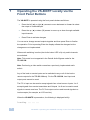
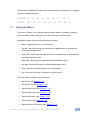
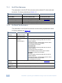
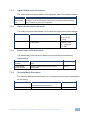
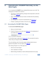
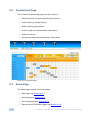
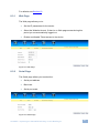
K R A ME R E LE CT R O N IC S L T D . USER MANUAL MODEL: VS-808TP 8x8 Twisted Pair Matrix Switcher P/N: 2900-300147 Rev 1 Contents 1 Introduction 1 2 2.1 2.2 Getting Started Achieving the Best Performance Using Twisted Pair Cable 2 2 2 3 Overview 3 4 Defining the VS-808TP 8x8 Twisted Pair Matrix Switcher 4 5 Installing the VS-808TP in a Rack 6 6 6.1 6.2 6.3 6.4 6.5 7 7.1 Connecting the VS-808TP Connecting a Serial Data Source to the VS-808TP RS-232 Data Port Connecting a Serial Controller to the VS-808TP Connecting to the VS-808TP via Ethernet Connecting the Balanced/Unbalanced Stereo Audio Output Wiring the CAT 5 Line In/Line Out RJ-45 Connectors Operating the VS-808TP Locally via the Front Panel Buttons Using the Menu 7 8 8 10 12 13 14 15 8 8.1 8.2 8.3 8.4 8.5 9 Operating the VS-808TP Remotely via the Web Pages Accessing the VS-808TP Web Pages Connections Page Setup Page User Management Firmware Technical Specifications 19 19 20 20 23 23 24 10 10.1 10.2 11 11.1 Default Parameters Default Communication Parameters Default Logon Credentials Kramer Protocol Kramer Protocol 2000 25 25 25 26 26 Figures Figure 1: VS-808TP 8x8 Twisted Pair Matrix Switcher Front Panel Figure 2: VS-808TP 8x8 Twisted Pair Matrix Switcher Rear Panel Figure 3: Connecting the VS-808TP 8x8 Twisted Pair Matrix Switcher Figure 4: Crossed Cable RS-232 Connection Figure 5: Straight Cable RS-232 Connection with a Null Modem Adapter Figure 6: Wiring for an RS-485 Serial Data Source Figure 7: Wiring for an RS-422 Serial Data Source Figure 8: Local Area Connection Properties Window Figure 9: Internet Protocol (TCP/IP) Properties Window Figure 10: Balanced Stereo Audio Connection Figure 11: Unbalanced Stereo Audio Connection Figure 12: CAT 5 Pinout Figure 13: Web Browser Address Bar Figure 14: Connections Page Figure 15: Web Page Contents 4 5 7 9 9 10 10 11 12 13 13 13 19 20 21 i Figure 16: Serial Page Figure 17: Port Name Page Figure 18: Data and Audio Processing Page Figure 19: User Management Page Figure 20: Firmware Page ii 21 22 22 23 23 VS-808TP - Contents 1 Introduction Welcome to Kramer Electronics! Since 1981, Kramer Electronics has been providing a world of unique, creative, and affordable solutions to the vast range of problems that confront video, audio, presentation, and broadcasting professionals on a daily basis. In recent years, we have redesigned and upgraded most of our line, making the best even better! Our 1,000-plus different models now appear in 11 groups that are clearly defined by function: GROUP 1: Distribution Amplifiers; GROUP 2: Switchers and Routers; GROUP 3: Control Systems; GROUP 4: Format/Standards Converters; GROUP 5: Range Extenders and Repeaters; GROUP 6: Specialty AV Products; GROUP 7: Scan Converters and Scalers; GROUP 8: Cables and Connectors; GROUP 9: Room Connectivity; GROUP 10: Accessories and Rack Adapters and GROUP 11: Sierra Video Products. Congratulations on purchasing your Kramer VS-808TP 8x8 Twisted Pair Matrix Switcher which is ideal for long range graphics distribution and multimedia applications. VS-808TP - Introduction 1 2 Getting Started We recommend that you: • Unpack the equipment carefully and save the original box and packaging materials for possible future shipment • Review the contents of this user manual Use Kramer high performance, high resolution cables • i 2.1 Use only the power cord supplied with the device Go to http://www.kramerelectronics.com to check for up-to-date user manuals, application programs and to check whether firmware upgrades are available (where appropriate). Achieving the Best Performance To achieve the best performance: • Use only good quality connection cables to avoid interference, deterioration in signal quality due to poor matching, and elevated noise levels (often associated with low quality cables) • Do not secure the cables too tightly or too loosely. Leave a small amount of slack • Avoid interference from neighboring electrical appliances that may adversely influence signal quality • Position your Kramer VS-808TP away from moisture, excessive sunlight and dust 2.2 Using Twisted Pair Cable Kramer engineers have developed special twisted pair cables to best match our digital twisted pair products; the Kramer: BC-DGKat524 (CAT 5 24 AWG), the Kramer: BC-DGKat623 (CAT 6 23 AWG cable), and the Kramer: BC-DGKat7a23 (CAT 7a 23 AWG cable). These specially built cables significantly outperform regular CAT 5/CAT 6/CAT 7a cables. 2 VS-808TP - Getting Started 3 Overview Thank you for purchasing the Kramer VS-808TP 8x8 Twisted Pair Matrix Switcher. This unique matrix switcher which utilizes economical TP (Twisted Pair) cabling often pre-installed in buildings these days, routes and distributes signals both from a local and/or remote source, and at extended ranges. It is designed especially for installations where a high level of control possibilities is required from extended distances. Typical uses include presentation and multimedia applications, as well as long-range graphics distribution and control for schools, hospitals, security, and stores. The VS-808TP features: • Eight inputs and eight outputs for remote connection to compatible TP transmitters and receivers • A switchable local input (built-in transmitter) and output (built-in receiver) allowing direct connection of the signals (up to WUXGA, audio and RS-232) for the units located near to the switcher (TP-133/TP-134 only) • Follow or breakaway switching for audio signals • Baud rate of up to 115200 for full-duplex RS-232 • Two-line LCD display for separate route indication of video, audio or RS-232 • Control via front panel buttons, RS-232, RS-485 and Ethernet • 15 user-programmable presets for quick-change configurations • Kramer 2000 communication protocol (limited) • 100-230V AC worldwide power supply • Standard 1U 19” rack mount size VS-808TP - Overview 3 4 4 Defining the VS-808TP 8x8 Twisted Pair Matrix Switcher Figure 1 defines the front panel of the VS-808TP. VS-808TP – Defining the VS-808TP 8x8 Twisted Pair Matrix Switcher Figure 1: VS-808TP 8x8 Twisted Pair Matrix Switcher Front Panel # Feature Function 1 AUDIO Button Press to display/switch audio status. Press again to display/switch video/RS-232 status 2 MENU Button Press to display the menu. Press again to escape the menu and display video switching 3 Arrow keypad When switching is displayed: press the left (◄) and right (►) arrows to move forward and backward to select the output of a switched pair. Press the up (▲) and down (▼) arrows to move up or down through available input channels. When the menu is displayed: press the up (▲) and down (▼) arrows to move up or down through available sub-menus. Press the left (◄) and right (►) a rrows to move through parameter values 4 ESC Button When the menu is displayed: press to move up one menu level or press repeatedly to exit the menu. When audio switching is displayed: press to display video switching 5 ENTER Button When audio switching is displayed: press to accept the selected out/in channels. When the menu is displayed: press to accept the selected parameter value 6 7 LCD Readout IN Display Displays the selected switched inputs OUT Display Displays the selected switched outputs VS-808TP – Defining the VS-808TP 8x8 Twisted Pair Matrix Switcher Figure 2 defines the rear panel of the VS-808TP. Figure 2: VS-808TP 8x8 Twisted Pair Matrix Switcher Rear Panel # Feature Function 8 9 10 11 Unbalanced AUDIO Connectors Balanced IN 3.5mm mini jack Connect to the output of the unbalanced stereo audio source (for example, the audio output of the laptop) OUT 3.5mm mini jack Connect to the input of the unbalanced stereo audio acceptor (for example, the audio input of the AV system) IN 5-pin terminal block Connect to the output of the balanced stereo audio source OUT 5-pin terminal block Connect to the input of the balanced stereo audio acceptor 12 RS-485/RS-422 5-Pin Terminal Block Connect to the serial controller 13 RS-232 (DATA) 9-pin D-sub Connector Connect to the serial data source 14 ETHERNET RJ-45 Connector Connect via a LAN to the Ethernet port on the PC controller 15 INPUTS 1 ~ 8 RJ-45 Connectors Connect to the TP transmitters (for example, TP-133 or TP-125) 16 OUTPUTS 1 ~ 8 RJ-45 Connectors Connect to the TP receivers (for example, TP-134 or TP-126) 17 Chassis Ground Terminal Terminal for grounding the chassis to the common ground of the system 18 19 20 AC Mains Module Mains socket Connect the mains power cord Mains fuse holder Fuse for protecting the device Mains switch Turn the device on and off 21 PC IN 15-pin HD VGA Connector 22 PC OUT 15-pin HD VGA Connector Connect to the output of the VGA (up to WUXGA) source (for example, PC graphics card) Connect to the input of the VGA acceptor (for example, LCD monitor) 23 RS-232 (CONTROL) 9-pin D-sub Connector Connect to the serial controller 5 5 6 Installing the VS-808TP in a Rack VS-808TP - Installing the VS-808TP in a Rack 6 Connecting the VS-808TP i Always switch off the power to any device before connecting it to your VS-808TP. After connecting your VS-808TP, connect its power and then switch on the power to the other devices. Figure 3: Connecting the VS-808TP 8x8 Twisted Pair Matrix Switcher To connect the VS-808TP as illustrated in the example in Figure 3: 1. For a local video and audio source connect: A VGA source (for example, the graphics output of a laptop) to the PC In 15-pin HD (M) connector VS-808TP - Connecting the VS-808TP 7 An audio source (for example, the audio output of a laptop) to the Audio In 3.5mm mini jack 2. For a local video and audio acceptor connect: The PC Out 15-pin HD (F) connector to the video input of the acceptor (for example, an AV system) The Audio Out 3.5mm audio jack to the audio input of the acceptor 3. For remote inputs and outputs: Connect up to eight compatible TP transmitters (for example, TP-133/TP-125) to the TP INPUTS 1 to 8 Connect up to eight compatible TP receivers (for example, TP-134/TP-126) to the TP OUTPUTS 1 to 8 Note: The TP-134 transmitter can be paired only with a TP-134 receiver, and the TP-125 transmitter can be paired only with a TP-126 receiver. Do not use both the TP-133/TP-134 and TP-125/TP-126 in the same system as depending on the switcher setup only one will work. 6.1 Connecting a Serial Data Source to the VS-808TP RS-232 Data Port You can connect a serial data source to the VS-808TP via RS-232 to control remote acceptors (for example, monitors). The RS-232 data source is connected to the RS-232 (DATA) port. A null-modem adapter is not required for this connection and a straight-through cable can be used. 6.2 Connecting a Serial Controller to the VS-808TP You can control the VS-808TP via one of three types of serial connections: 8 • RS-232 • RS-485 • RS-422 VS-808TP - Connecting the VS-808TP 6.2.1 Connecting an RS-232 Serial Controller to the VS-808TP RS-232 Control Port You can connect to the unit (the RS-232 CONTROL port) via a crossed RS-232 connection, using for example, a PC. A crossed cable or null-modem is required as shown in method A and B respectively. If a shielded cable is used, connect the shield to pin 5. Method A (Figure 4)—Connect the RS-232 9-pin D-sub port on the unit via a crossed cable (only pin 2 to pin 3, pin 3 to pin 2, and pin 5 to pin 5 need be connected) to the RS-232 9-pin D-sub port on the PC. Note: There is no need to connect any other pins. 5 4 3 2 9 8 7 6 9 8 7 6 1 5 4 3 2 PC 1 Figure 4: Crossed Cable RS-232 Connection Hardware flow control is not required for this unit. In the rare case where a controller requires hardware flow control, short pin 1 to 7 and 8, and pin 4 to 6 on the controller side. Method B (Figure 5)—Connect the RS-232 9-pin D-sub port on the unit via a straight (flat) cable to the null-modem adapter, and connect the null-modem adapter to the RS-232 9-pin D-sub port on the PC. The straight cable usually contains all nine wires for a full connection of the D-sub connector. Because the null-modem adapter (which already includes the flow control jumpering described in Method A above) only requires pins 2, 3 and 5 to be connected, you are free to decide whether to connect only these 3 pins or all 9 pins. 9 8 7 6 5 4 3 2 1 Null-Modem Adapter to PC Figure 5: Straight Cable RS-232 Connection with a Null Modem Adapter VS-808TP - Connecting the VS-808TP 9 6.2.2 Connecting an RS-485/RS422 Serial Data Source to the VS-808TP To connect an RS-485/RS-422 serial data source to the VS-808TP: • Connect the RS-485/RS-422 serial data source to the RS-485/RS-422 terminal block connector on the rear panel of the device as shown in Figure 6 or Figure 7 Figure 6: Wiring for an RS-485 Serial Data Source Figure 7: Wiring for an RS-422 Serial Data Source 6.3 Connecting to the VS-808TP via Ethernet You can connect the VS-808TP via Ethernet using either of the following methods: • • A crossover cable (see Section 6.3.1) for direct connection to the PC A straight through cable (see Section 6.3.2) for connection via a network hub or network router After connecting the Ethernet port, you have to install and configure your Ethernet Port. For detailed instructions, see the Ethernet Configuration Guide (Lantronix) in the technical support section on our Web site http://www.kramerelectronics.com. 6.3.1 Connecting the Ethernet Port directly to a PC A crossover cable is recommended for identification of the factory default IP Address of the VS-808TP during the initial configuration. 10 VS-808TP - Connecting the VS-808TP To configure your PC after connecting the Ethernet port: 1. Right-click the My Network Places icon on your desktop. 2. Select Properties. 3. Right-click Local Area Connection Properties. 4. Select Properties. The Local Area Connection Properties window appears. 5. Select the Internet Protocol (TCP/IP) and click the Properties Button. Figure 8: Local Area Connection Properties Window 6. Select Use the following IP Address and enter the details as shown in Figure 9. VS-808TP - Connecting the VS-808TP 11 Figure 9: Internet Protocol (TCP/IP) Properties Window 7. Click OK. 6.3.2 Connecting to the Ethernet Port via a Network Switch/Hub To connect to the Ethernet port on the VS-808TP via a network switch/hub: • Connect the PC to the Ethernet network switch/hub using a straight through cable 6.4 Connecting the Balanced/Unbalanced Stereo Audio Output This section illustrates how to wire the devices to the balanced audio output: 12 • A balanced stereo output connection, see Figure 10 • An unbalanced stereo output connection, see Figure 11 VS-808TP - Connecting the VS-808TP Figure 10: Balanced Stereo Audio Connection Figure 11: Unbalanced Stereo Audio Connection 6.5 Wiring the CAT 5 Line In/Line Out RJ-45 Connectors This section defines the CAT 5 pinout, using a straight pin-to-pin cable with RJ-45 connectors. i Note, that the cable Ground shielding must be connected / soldered to the connector shield. EIA /TIA 568B PIN 1 Wire Color Orange / White 2 Orange 3 Green / White 4 Blue 5 Blue / White 6 Green 7 Brown / White 8 Brown Pair 1 4 and 5 Pair 2 1 and 2 Pair 3 3 and 6 Pair 4 7 and 8 VS-808TP - Connecting the VS-808TP Figure 12: CAT 5 Pinout 13 7 Operating the VS-808TP Locally via the Front Panel Buttons The VS-808TP is operated using the front panels buttons as follows: • Press the left (◄) or right (►) arrows to move backward or forward to select the output of a switched pair • Press the up (▲) or down (▼) arrows to move up or down through available input channels • Press Enter to activate changes You can set or change several outputs together and then press Enter to finalize the operation. Prior to pressing Enter the display reflects the changes but the changes are not implemented. When audio switching is active (the Audio button LED is lit) only audio channels are switched. Note: This mode is not supported in the Data & Audio Bypass mode for the TP-125/126. Note: Performing a video switch overwrites a previously implemented audio switch. Any of the local or remote inputs can be switched to any or all of the local or remote outputs for the TP-133/134 only. For the TP-125/126, local input and output ports cannot be used. The PC In input can be used to accept signals from a local source. Inputs 1 to 8 accept signals from remote transmitters and Outputs 1 to 8 can be used to send signals to remote receivers. The PC Out output can be used to send signals to a local acceptor (for example, an LCD monitor). When the VS-808TP is powered on, the following is displayed briefly: Loading ......... 14 VS-808TP - Operating the VS-808TP Locally via the Front Panel Buttons The device then displays the last active video switching configuration, an example of which is displayed below. OUTPUT 01 INPUT 7.1 01 02 02 03 03 04 05 04 06 05 07 06 07 08 08 L L Using the Menu The menu is shown on the display when the Menu button is pressed. Pressing either the Menu button a second time or the Esc button exits the menu. Navigation through the menu is performed as follows: • Menu—display the menu or exit the menu • Up (▲)—scroll up through the sub-menus or parameters, or increase the selected parameter value • Down (▼)—scroll down through sub-menus or parameters, or decrease the selected parameter value • Right (►)—Move right through the selected parameter value • Left (◄)—Move left through the selected parameter value • Enter—Select the indicated sub-menu or parameter • Esc—Move up one level in the menu or exit the menu The main menu comprises seven sections: • Set IP Port (see Section 7.1.1) • Set Serial Port (see Section 7.1.2) • Adjust Video Level (see Section 7.1.3) • Adjust Audio Level (see Section 7.1.4) • Save/Load Profile (see Section 7.1.5) • Security Mode (see Section 7.1.6) • Data and Audio Processing (see Section 7.1.7) VS-808TP - Operating the VS-808TP Locally via the Front Panel Buttons 15 7.1.1 Set IP Port Sub-menu The parameters in the Set IP Port sub-menu set the network IP values and reset the device. For factory defaults see Section 10. Parameter Description IP Address Subnet Mask Gateway Default IP Settings Save and Reset the Device Exit Without Save Sets the IP network address Any valid IP address Sets the IP network mask Any valid subnet mask Sets the IP gateway address Any valid gateway address Sets the IP settings to the factory default (see Section 10.1) Saves changes made to settings and resets the device Exits without saving any changed settings 7.1.2 Options Set Serial Port Sub-menu The parameters in the Serial Port sub-menu set the serial port parameter values. For factory defaults see Section 10. Parameter Description Options Serial Port Address Baud Rate Sets the serial machine number Sets the serial port baud rate in bps Sets the serial port mode of communication 1 to 16 Serial Port Mode Default Serial Settings Save and Reset the Device Exit Without Save 16 9600, 19200, 38400 or 115200 RS-232 1. RS-232 (Data): Exchange data with the remote output acceptors 2. RS-232 (Control): Accept Kramer Protocol 2000 commands to switch the VS-808TP 3. RS-422/485: No function RS-422/RS-485 1. RS-232 (Data): Exchange data with the remote output acceptors 2. RS-232 (Control): No function 3. RS-422/485: Accept Kramer Protocol 2000 commands to switch the VS-808TP BYPASS 1. RS-232 (Data): Exchange data with the remote output acceptors 2. RS-232 (Control): Accept Kramer Protocol 2000 commands to switch the VS-808TP 3. RS-422/485: No function Sets the serial port parameters to the factory default (see Section 10.1) Save any changes to settings and reset the device Exit without saving and changed settings VS-808TP - Operating the VS-808TP Locally via the Front Panel Buttons 7.1.3 Adjust Video Level Sub-menu The Video Level sub-menu allows you to adjust the video level of each channel. 7.1.4 Parameter Description Optimize Video Output Port Video quality adjustment is done automatically at every connection change or it can be manually forced via the front panel or the Web pages. For local ports only the gain is adjusted Adjust Audio Level Sub-menu The Audio Level sub-menu allows you to adjust the audio level of each channel. 7.1.5 Parameter Description Options Audio Output Port Selects the audio output to adjust its level Audio Level Sets the audio level of the selected output or all outputs 01, 02,03, 04, 05, 06, 07, 08, All, L (local) Stored Values: 0-15 where 0 = mute, 01 = -25dB and 15 = 6dB Save/Load Profile Sub-menu The Save/Load Profile sub-menu allows you to save and recall switching configurations. 7.1.6 Parameter Description Options Load to a Profile Number Call a Saved Profile Number Saves the current configuration to the selected setup Recalls a saved setup to be the current configuration 0 to 15 0 to 15 Security Mode Sub-menu The Security Mode sub-menu allows you to set the security access and password for the device. Parameter Description Options Password Required Turns on and off the requirement for a password to access the menu Sets the password for access Yes, No Change password VS-808TP - Operating the VS-808TP Locally via the Front Panel Buttons 0000 to 9999 17 7.1.7 Data and Audio Processing Sub-menu The Data and Audio Processing sub-menu allows you set the processing for the model of TP transmitter being used. 18 Parameter Description Options Processing Mode Sets the processing mode for the data and audio depending on the TP transmitter in use: Default=TP133/134 Bypass=TP-125/126 Default, Bypass Default—Default VS-808TP - Operating the VS-808TP Locally via the Front Panel Buttons 8 Operating the VS-808TP Remotely via the Web Pages You can operate the VS-808TP using a standard Web browser over a LAN. The Web pages are divided into four sections: • Connections—Controls switching, video gain and compensation, and audio volume (see Section 8.2) • Setup—Controls Web, serial, port names, and data and audio processing (see Section 8.3) 8.1 • User Management—Controls user administration (see Section 8.4) • Firmware—Updating the firmware of the device (see Section 8.5) Accessing the VS-808TP Web Pages To access the VS-808TP Web pages: 1. Open your Internet browser. 2. Enter the IP address of the device (see Section 10) in the address bar of your browser (see Figure 13). Figure 13: Web Browser Address Bar For the default logon credentials see Section 10.2. We recommend for security reasons that you change the defaults at first logon. The main switching control Connections page is displayed which shows a graphical interpretation of the front panel (see Figure 14). After making changes on any of the pages click: • Submit to save the changes • Clear to abandon the changes • Default Setting (if available) to load the default parameters for the page VS-808TP - Operating the VS-808TP Remotely via the Web Pages 19 8.2 Connections Page The Connections (switching) page provides control of: • Combined video and audio switching (blue square) • Video switching (orange square) • Audio switching (gray square) • Video port gain and compensation optimization • Audio port volume • Saving and loading preset switching configurations Figure 14: Connections Page 8.3 Setup Page The Setup pages consist of four sub-pages: 20 • Web page (see Section 8.3.1) • Serial page (see Section 8.3.2) • Port Name page (see Section 8.3.3) • Data and Audio Processing page (see Section 8.3.4) VS-808TP - Operating the VS-808TP Remotely via the Web Pages For defaults see Section 10. 8.3.1 Web Page The Web page allows you to: • Set the IP parameters for the device • Select the Website timeout. If there is no Web page access during this period you are automatically logged out • Enable and disable Telnet access to the device Figure 15: Web Page 8.3.2 Serial Page The Serial page allows you to select the: • Serial port address • Baud rate • Serial port mode Figure 16: Serial Page VS-808TP - Operating the VS-808TP Remotely via the Web Pages 21 8.3.3 Port Name Page The Port Name page allows you to rename the ports. These names appear on the Connections page (see Section 8.2). Figure 17: Port Name Page 8.3.4 Data and Audio Processing Page The Data and Audio Processing page allows you to select either no processing or for the device to provide data and audio processing. Figure 18: Data and Audio Processing Page 22 VS-808TP - Operating the VS-808TP Remotely via the Web Pages 8.4 User Management The User Management page allows you to view, edit and delete current users, and add new ones (if you have user management rights authorization). Users can be given one of the following privilege levels: • User—Basic rights (perform switching, save and recall presets, and adjust audio level) • Super User—Full rights (no user management) • Administrator—Full rights and user management Figure 19: User Management Page 8.5 Firmware The firmware page allows you to upgrade the firmware of the device. Figure 20: Firmware Page VS-808TP - Operating the VS-808TP Remotely via the Web Pages 23 9 Technical Specifications SIGNAL INPUTS: SIGNAL OUTPUTS: CONTROL INPUTS/OUTPUTS: RESOLUTION (VIDEO): VIDEO CONTROL EQUALIZATION/GAIN AUDIO GAIN: MAXIMUM CABLE LENGTH: BAUD RATE (RS-232): POWER CONSUMPTION: DIMENSIONS: WEIGHT: ACCESSORIES: 24 8 CAT 5 remote transmitters on RJ-45 connectors 1 local RGBHV WUXGA on a 15-pin HD connector 1 local unbalanced stereo audio on a 3.5mm mini jack 1 local balanced stereo audio on a 5-pin terminal block 1 RS-232 (Data) input/output on a 9-pin D-sub connector 1 RS-485/RS-422 input/output on a 5-pin terminal block 8 CAT 5 remote receivers on RJ-45 connectors 1 local RGBHV WUXGA on a 15-pin HD connector 1 local unbalanced stereo audio on a 3.5mm mini jack 1 local balanced stereo audio on a 5-pin terminal block 1 RS-232 (Control) input on a 9-pin D-sub connector 1 Ethernet LAN on an RJ-45 connector Up to 1920 x 1200 @60Hz (WUXGA) depending on the transmitter/receiver Video quality adjustment is done automatically at every connection change or can be forced manually via the front panel 0-15 where 0=mute , 01=–25dB and 15=6dB 300m (984ft) 9600, 19200, 38400, 115200 100-240VAC, 50/60Hz, 23VA 19" x 9.4" x 1U (W, D, H) 3kg (6.6lbs) approx Power cord, rack “ears” VS-808TP - Technical Specifications 10 Default Parameters 10.1 Default Communication Parameters RS-232 Baud Rate 9600 Data Bits 8 Stop Bits 1 Parity None Command Format Hex Example (Output 1 to Input 1) H01H81H81H81 Ethernet To reset the IP settings to the factory reset values, power cycle the device while holding in the Factory Reset button located on the rear panel of the unit IP Address 192.168.1.39 Subnet mask 255.255.255.0 Default gateway 0.0.0.0 10.2 Default Logon Credentials Logon Credentials Name kramer Password kramer VS-808TP - Default Parameters 25 11 Kramer Protocol The VS-808TP supports the Kramer Protocol 2000. You can download our user friendly “Software for Calculating Hex Codes for Protocol 2000” from the technical support section at http://www.kramerelectronics.com. 11.1 Kramer Protocol 2000 This RS-232/RS 485/Ethernet communication protocol (Version 0.51) uses four bytes of information as defined below. For serial communication parameters, see Section 10.1. Table 1: Protocol Definitions MSB LSB DESTINATION INSTRUCTION 0 D N5 N4 N3 N2 N1 7 6 5 4 3 2 1 0 1 I6 I5 I4 I3 I2 I1 I0 7 6 5 4 3 2 1 0 O5 O4 N0 1st byte INPUT 2nd byte OUTPUT 1 O6 O3 O2 O1 7 6 5 4 3 2 1 1 OVR X M4 M3 M2 M1 7 6 5 4 3 2 1 O0 0 3rd byte MACHINE NUMBER M0 0 4th byte 1st BYTE: Bit 7 – Defined as 0. D – “DESTINATION”: 0 - for sending information to the switchers (from the PC); 1 - for sending to the PC (from the switcher). N5…N0 – “INSTRUCTION” The function that is to be performed by the switcher(s) is defined by the INSTRUCTION (6 bits). Similarly, if a function is performed via the machine’s keyboard, then these bits are set with the INSTRUCTION NO., which was performed. The instruction codes are defined according to the table below (INSTRUCTION NO. is the value to be set for N5…N0). 2nd BYTE: Bit 7 – Defined as 1. I6…I0 – “INPUT”. When switching (ie. instruction codes 1 and 2), the INPUT (7 bits) is set as the input number which is to be switched. Similarly, if switching is done via the machine’s front-panel, then these bits are set with the INPUT NUMBER which was switched. For other operations, these bits are defined according to the table. 3rd BYTE: Bit 7 – Defined as 1. O6…O0 – “OUTPUT”. 26 VS-808TP - Kramer Protocol When switching (ie. instruction codes 1 and 2), the OUTPUT (7 bits) is set as the output number which is to be switched. Similarly, if switching is done via the machine’s front-panel, then these bits are set with the OUTPUT NUMBER which was switched. For other operations, these bits are defined according to the table. 4th BYTE: Bit 7 – Defined as 1. Bit 5 – Don’t care. OVR – Machine number override. M4…M0 – MACHINE NUMBER. Used to address machines in a system via their machine numbers. When several machines are controlled from a single serial port, they are usually configured together with each machine having an individual machine number. If the OVR bit is set, then all machine numbers will accept (implement) the command, and the addressed machine will reply. For a single machine controlled via the serial port, always set M4…M0 = 1, and make sure that the machine itself is configured as MACHINE NUMBER = 1. Table 2: Instruction Codes for Protocol 2000 # INSTRUCTION DESCRIPTION DEFINITION FOR SPECIFIC INSTRUCTION INPUT OUTPUT 1 SWITCH VIDEO 2 SWITCH AUDIO 3 STORE VIDEO STATUS Set equal to video input which is to be switched (0 = disconnect) Set equal to audio input which is to be switched (0 = disconnect) Set as SETUP # 4 RECALL VIDEO STATUS Set as SETUP # Set equal to video output which is to be switched (0 = to all the outputs) Set equal to audio output which is to be switched (0 = to all the outputs) 0 - to store 1 - to delete 0 NOTE 1 1 1, 2 1, 2 Note: All values in the table are decimal, unless otherwise stated. Notes on the above table: NOTE 1 - For example, if the HEX code 01 85 88 83 was sent from the PC, then the switcher (machine 3) will switch input 5 to output 8. When the PC sends one of the commands in this group to the switcher, then, if the instruction is valid, the switcher replies by sending to the PC the same four bytes that it was sent (except for the first byte, where the DESTINATION bit is set high). NOTE 2 - SETUP # 0 is the present setting. SETUP # 1 and higher are the settings saved in the switcher's memory, (i.e. those used for Store and Recall). VS-808TP - Kramer Protocol 27 ! ! P/N: 2900- 300147 " " Rev: 1