1
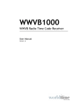
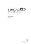
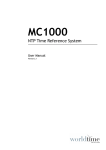
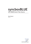
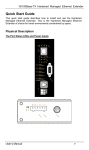
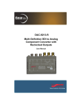
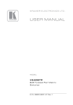
GPS6000-PRO
GNSS Time Receiver
User Manual
Version 1.0
Copyright
Software Licence
© 2015 World Time Solutions Limited. All Rights Reserved.
All information contained within this document is the property of
World Time Solutions Limited and cannot be used or reproduced
by any person or company without written consent from World
Time Solutions Limited.
World Time Solutions Limited reserves the right to make periodic
amendments to the information in this document without notice.
Trademarks
All registered trademarks and trademarks are property of their
respective owners.
RoHS Compliance
World Time Solutions Limited works with its suppliers to ensure
all products comply with the Restriction of Hazardous Substances
(RoHS) directive.
For further information, please visit our web site at:
www.worldtimesolutions.com/rohs.html
Disposal
This product contains proprietary World Time Solutions Limited
software. This software is supplied under the World Time
Solutions Limited Software Licence Agreement.
For further information or to view a copy of the software licence,
please visit:
www.worldtimesolutions.com
Limited Warranty
The GPS6000-PRO GPS Time Receiver is guaranteed against
failure due to faulty parts or workmanship for a period of five (5)
years from date of purchase.
In the event of product failure due to faulty parts or workmanship
within the warranty period, World Time Solutions Limited, at
its own discretion, will either (a) repair the product, (b) supply
a replacement product, (c) supply a functionally equivalent
replacement product, or (d) refund the purchase price of the
product.
The limited warranty will not apply if (a) the product has not been
installed or operated as per our instructions, (b) the product has
been modified in anyway.
In the event of failure, the GPS6000-PRO should be returned
to the manufacturer for inspection and repair. Please visit our
support pages for further details:
www.worldtimesolutions.com/support.html
Technical Support
Please dispose of this unit properly. To minimize pollution and
help protect the environment, this unit should be recycled.
For further information and/or to view a copy of the World Time
Solutions Limited Waste Electrical and Electronic Equipment
Policy, please visit our web site at:
To obtain help with the installation or operation of the
GPS6000‑PRO, please visit our web site at:
www.worldtimesolutions.com/support.html
www.worldtimesolutions.com/recycle.html
II
GPS6000-PRO - GPS Time Receiver - User Manual - Version 1.0
1 - Introduction
1.1 - Overview
The GPS6000-PRO accurately synchronises your time server with
international atomic standards. Incorporating the latest in GNSS
technology and multi-constellation support (GPS/GLONASS/Galileo
ready), the GPS6000-PRO ensures accurate and reliable time on
your systems, even in hostile RF environments.
With 32 satellite parallel tracking and class-leading high performance
design, the GNSS decoder supplies time data accurate to within 30
nsec of UTC. The user programmable cable delay compensation
ensures timing accuracy is maintained, even over long cable runs.
The system has been engineered to ensure reliable performance. The
high sensitivity GPS6000 decoder allows for operation in the most
demanding weak signal and hostile RF environments. The GPS6000
fully integrates with your time server, providing real time diagnostics
and active antenna monitoring. Advanced anti-jam technology and
multi-constellation support further increase system reliability.
Installing the GPS6000 is simple. All cables are supplied preterminated. The GPS6000 has also been purpose designed to allow
cost saving installation into your data centre, optionally connecting to
your time server via existing cat 5 structured cabling.
1.2 - Scope of supply
Scope of supply:
• 1 x multi-constellation GNSS anti-jam antenna
• 1 x multi-constellation GNSS decoder
• 1 x antenna mount
• 1 x lightning arrester
• 1 x 8m antenna coax cable
• 1 x 1m arrester coax cable
• 1 x 5m output cable
• 1 x user manual
GPS6000-PRO - GPS Time Receiver - User Manual - Version 1.0
1
Section 1: Introduction
1.3 - Options
• GPS6000-ANT-15: 15m (49ft) antenna cable
• GPS6000-ANT-25: 25m (82ft) antenna cable
• GPS6000-OUT-15: 15m (49ft) output cable
• GPS6000-OUT-50: 50m (164ft) output cable
• GPS6000-OUT-150: 150m (492ft) output cable
• GPS6000-PRO-GPS: GPS6000-PRO with GPS only support
• GPS6000-PRO-GLONASS: GPS6000-PRO with GLONASS
only support
2
GPS6000-PRO - GPS Time Receiver - User Manual - Version 1.0
2 - The GPS6000-PRO in detail
2.1 - The GNSS anti-jam antenna
The GNSS antenna receives data from the GPS and GLONASS global
navigation satellite systems. The antenna incorporates anti-jamming
technology and is designed to withstand extreme temperature
environments, excessive vibration, rain, snow and sunlight.
Figure 2.1 - The anti-jam antenna
2.2 - The GNSS decoder
The GNSS decoder converts satellite data into highly accurate time
information. The cable delay offset function ensures timing accuracy
is maintained over long cable runs.
OUTPUT
A
CABLE DELAY OFFSET
ANTENNA
B
C
D
STATUS
GPS6000 - GNSS TIME DECODER
www.worldtimesolutions.com
Figure 2.2 - The GNSS Decoder (front)
Figure 2.3 - The GNSS Decoder (rear)
2.3 - The lightning arrester
The multi-strike fast response lightning arrester connects between the
antenna and the GNSS decoder. The lightning arrester protects the
GNSS decoder and attached systems from damage due to a lightning
strike.
Figure 2.4 - The lightning arrester
GPS6000-PRO - GPS Time Receiver - User Manual - Version 1.0
3
3 - Installing the GPS6000
Installing the GPS6000-PRO is a straightforward procedure. All cables
are supplied pre-terminated and no specialist tools are required.
However, to ensure reliable and safe operation, care should be taken
selecting appropriate locations for the GNSS antenna and lightning
arrester.
Please follow the installation guidelines below to ensure a trouble-free
installation.
3.1 - System installation overview
GNSS antenna
Antenna mount
Antenna cable
(8m TNC - TNC
RG-58C/U coax)
Outside of building (on roof)
Inside building
Lightning arrester
(connected to low
impedance ground)
Arrester cable
(1m TNC - SMA
RG-58C/U coax)
CABLE DELAY OFFSET
GNSS decoder
ANTENNA
STATUS
GPS6000 - GNSS TIME DECODER
Output cable
(Belden 9502 /
structured cabling)
Time server
Figure 3.1 - System installation overview
4
GPS6000-PRO - GPS Time Receiver - User Manual - Version 1.0
Section 3: Installing the GPS6000-PRO
3.2 - Installing the antenna
3.2.1 - Selecting an installation location
The antenna should be installed externally, with the maximum
possible sky visibility. For most installations, the ideal location will
be the roof of your building (the antenna is able to withstand extreme
temperatures, excessive vibration, rain, snow and sunlight).
Ideally, the antenna should have a clear uninterrupted 360º view of
the horizon. For installations where an unobstructed view of the sky
is not practical, the antenna should be installed with as large a view
as possible of the sky towards the equator. Installing the antenna
with a substantially reduced view of the sky will degrade system
performance and may increase synchronisation time.
3.2.2 - Mounting the antenna
The antenna should be mounted with the top of the dome facing
directly upwards and secured using the stainless steel surface mount
antenna bracket. Care should be taken to ensure the fixings used (not
supplied) are suitable for the application. Figure 3.2 below details the
antenna mount fixing dimensions.
Fixing holes on a
27.25mm radius
3 x 7.5mm fixing holes
Figure 3.2 - Antenna mount fixing dimensions
3.2.3 - The antenna cable
The GPS6000-PRO is supplied as standard with an 8m (26ft)
pre‑terminated RG-58C/U TNC to TNC coaxial cable for connection to
the lightning arrester. Longer antenna cables are optionally available
if required.
GPS6000-PRO - GPS Time Receiver - User Manual - Version 1.0
5
Section 3: Installing the GPS6000-PRO
3.3 - Installing the lightning arrester
The multi-strike fast response lightning arrester connects between the
antenna and GNSS decoder. The lightning arrester provides surge
protection for the GNSS decoder (and attached systems) in the event
of a lightning strike.
Please note: The lightning arrester must not be
installed externally.
The lightning arrester should be installed internally at the point where
the antenna cable enters the building. It is important that the lightning
arrester is grounded to a low impedance ground system for proper
operation.
The lightning arrester is supplied with a separate
instruction sheet with full installation details. Please consult this separate instruction sheet
carefully when installing your lightning arrester.
3.4 - Installing the GNSS decoder
3.4.1 - Mounting the GNSS decoder
The GNSS decoder converts the raw satellite data into highly accurate
time information. The decoder should be installed internally, close to
the output of the lightning arrester (the system is supplied with a 1m
(3ft) pre‑terminated coaxial cable for connection between the lightning
arrester and the GNSS decoder).
Please note: The GNSS decoder is not suitable for
external installation.
The decoder should be secured in position using the integral surface
mounting brackets. Care should be taken to ensure the fixings used
(not supplied) are suitable for the application. Figure 3.3 below details
the enclosure bracket fixing dimensions.
2 x 5.5mm fixing points.
81.5mm centre spacing
Figure 3.3 - GNSS decoder enclosure mounting dimensions
6
GPS6000-PRO - GPS Time Receiver - User Manual - Version 1.0
Section 3: Installing the GPS6000-PRO
3.4.2 - Cable connections
The connection between the lightning arrester and the GNSS decoder
should be made using the supplied 1m (3ft) pre‑terminated RG-58C/U
TNC to SMA coaxial cable.
The system is supplied as standard with a pre‑terminated 5m (16ft)
output cable for the connection between the GNSS decoder and
your time server. Longer cables are optionally available if required.
Alternatively, the output cable may be extended using Belden 9502
cable up to a maximum total length of 150m (492ft). Table 3.1 details
the cable colour scheme.
Terminal ID
Cable colour code
Cable screen drain wire
GND
A
Black / Red
B
Red
C
Black / White
D
White
Table 3.1 - Output cable connection detail
For low smoke/plenum applications, the supplied cable should be
substituted for a Belden 82502 (or equivalent) type cable.
3.4.3 - Optional connection using structured cabling
To enable simple installation into a data centre or office complex,
the GNSS decoder may be connected to your time server using
category 5, category 5e or category 6 structured cabling.
Table 3.2 below details the suggested RJ45 / 8P8C pin connections.
Using this configuration, cable lengths of up to 300m (984ft) may be
used reliably.
RJ45 /
8P8C pin
T568A Colour
T568B Colour
GNSS decoder
output pin
1
White / Green
White / Orange
A
2
Green
Orange
B
3
White / Orange
White / Green
A
4
Blue
Blue
D
5
White / Blue
White / Blue
C
6
Orange
Green
B
7
White / Brown
White / Brown
GND
8
Brown
Brown
GND
Table 3.2 - RJ45 / 8P8C structured cabling wiring detail
GPS6000-PRO - GPS Time Receiver - User Manual - Version 1.0
7
Section 3: Installing the GPS6000-PRO
3.5 - The cable delay offset
The GPS6000-PRO is capable of providing time data accurate to
within 30 nsec of UTC. At this level of accuracy, taking account of
cable lengths becomes critical. Every metre of cable between the
GNSS antenna and your time server causes an additional error of
approximately 5 nsec (see note over page). For long cable lengths,
this accumulated error can become very significant.
The cable delay offset provides a simple solution to correct for errors
due to cable propagation delays. The total cable length between the
GNSS antenna and your time server is entered using the switch bank.
The GNSS decoder then automatically advances the time data by the
required offset to correct for the cable propagation delay.
GPS6000-PRO systems are supplied with the correct cable delay
offset value pre‑programmed. For a typical installation, this preset
value should not need any adjustment. However, if required, the
cable delay offset can be programmed using the following guidelines.
3.5.1 - Programming the cable delay offset
Please note: The preset cable delay offset should
not normally require any adjustment.
The cable delay offset is programmed in metres using the cable
delay offset switch bank. The total cable length (in metres) should be
encoded in an 8 bit binary format and entered into the switch bank.
Switches set to on (the upper position) are summed. As shown in
figure 3.4 below, the left-hand switch is the most significant bit (128m)
and the right-hand switch the least significant digit (1m).
CABLE DELAY OFFSET
ANTENNA
STATUS
GPS6000 - GNSS TIME DECODER
add 1m to cable length
add 2m to cable length
add 4m to cable length
add 8m to cable length
add 16m to cable length
add 32m to cable length
add 64m to cable length
add 128m to cable length
Figure 3.4 - The cable delay offset switch bank
8
GPS6000-PRO - GPS Time Receiver - User Manual - Version 1.0
Section 3: Installing the GPS6000-PRO
For example, to set a total cable length of 14m (or 00001110 in binary),
set the 8m, 4m and 2m switches on (as shown in figure 3.5 below).
CABLE DELAY OFFSET
ANTENNA
STATUS
GPS6000 - GNSS TIME DECODER
8m, 4m and 2m switches set on (up)
Figure 3.5 - Example 14m cable delay offset
Alternatively, to set a total cable length of 59m (or 00111011 in binary),
set the 32m, 16m, 8m, 2m and 1m switches on (as shown in figure
3.6 below).
CABLE DELAY OFFSET
ANTENNA
STATUS
GPS6000 - GNSS TIME DECODER
32m, 16m, 8m, 2m and 1m switches set on (up)
Figure 3.6 - Example 59m cable delay offset
A NOTE REGARDING THE CABLE DELAY OFFSET ACCURACY:
The GPS6000-PRO advances the time data by 5 nsec for every additional metre
added to the cable delay offset value. This 5 nsec per metre value has been
chosen as a good approximation to the velocity of propagation for RG-58C/U (at
66%, or 5.05 nsec/m). However, users wishing to achieve the highest level of
accuracy should take account of the nominal velocity of propagation for Belden
9502 (at 60% or 5.56 nsec/m) and correspondingly increase the programmed cable
delay offset at longer output cable lengths.
GPS6000-PRO - GPS Time Receiver - User Manual - Version 1.0
9
4 - System operation
Operation of the GPS6000-PRO is fully automatic. The following
theory of operation is supplied as a reference, to allow the user to gain
a basic understanding of the technology used in the GPS6000-PRO.
4.1 - Theory of operation
When first powered-up, the GPS6000-PRO initiates a cold start
search acquisition process. Satellites are tracked from all available
GNSS constellations (GPS/GLONASS/Galileo ready) and an initial
location/timing solution is computed. Typically, the search acquisition
process will complete within one minute.
After the search process has been successfully completed, the
GPS6000‑PRO begins downloading GNSS almanac data (containing
orbit and status reference information for each satellite vehicle, along
with UTC offset data). The GPS6000-PRO must continuously track
the GNSS satellites for around 15 minutes to download a complete
almanac.
Once the almanac download is complete, the GPS6000‑PRO begins
transmitting time data and enters self‑survey mode. In self-survey
mode, the GPS6000-PRO computes a highly accurate reference
location by averaging multiple position fixes.
After a successful self‑survey has completed (approximately 35
minutes of uninterrupted GNSS tracking), the computed reference
location is stored and the GPS6000-PRO moves to high-accuracy
timing mode. In this mode, the GPS6000-PRO is able to provide time
data accurate to within 30 nsec of UTC.
Note that if your GPS6000-PRO has previously performed a full
self‑survey and the location has not changed, a new self-survey will
not be performed. The GPS6000-PRO will move directly from almanac
download to high-accuracy timing mode. If the GPS6000‑PRO has
previously performed a full self-survey and the location has changed,
a new self-survey will be performed.
4.2 - Operation in non-static applications
The GPS6000-PRO is optimised for use in static installations. In
normal operation, the GPS6000-PRO performs a self-survey then
switches to high-accuracy timing mode (where the system corrects
only for clock errors). In this mode, the GPS6000-PRO assumes the
location does not change.
It is possible to use the GPS6000-PRO in non-static applications.
However, the system will not operate in high-accuracy timing mode
and timing accuracy will be degraded.
10
GPS6000-PRO - GPS Time Receiver - User Manual - Version 1.0
Section 4: System operation
4.3 - Anti-jam protection
The GPS6000-PRO combines two discrete layers of anti-jam
protection. When used together, these systems provide a high level
of resistance against the affects of both GNSS spoofing and GNSS
jamming.
The GNSS antenna incorporates class leading anti-jam technology,
providing reliable operation, even in hostile RF environments.
The GNSS decoder provides a second layer of protection, with
advanced anti-spoofing functionality.
Please contact us if you require further details regarding the operation
of these functions.
4.4 - Synchronisation status
The status LED provides a visual indication of the synchronisation
status of your GPS6000-PRO. In normal operation, the status
LED will be flashing green. A red LED indicates the system is not
synchronised or there is an error. See table 4.1 for more details.
LED
Solid red
Single red flash
Single green flash
Double red flash
Triple red flash
Status
System booting
Searching / downloading almanac data
Locked
Antenna disconnected
Antenna shorted
Table 4.1 - Status LED functions
More detailed status information can be accessed via your time server.
The GPS6000-PRO fully integrates with your time server, providing
real time diagnostics and active antenna monitoring. Please refer to
the user manual for your time server for further details.
GPS6000-PRO - GPS Time Receiver - User Manual - Version 1.0
11
A - Specifications
Timing performance:
Synchronised accuracy:
30 nsec (1 sigma)
GNSS decoder:
GNSS engine:
Anti-jam capable, multi-constellation,
32 satellite parallel tracking
Minimum acquisition
sensitivity:
-148dBm (cold start)
Minimum tracking
sensitivity:
-160dBm
Operating temperature:
0 to 50ºC
Relative humidity:
0% - 95%, noncondensing
Enclosure:
85 x 65 x 30mm (3.35” x 2.56” x 1.18”)
aluminium enclosure with wall mount
brackets
Weight:
0.2 kg
Cable delay compensation:
User programmable
Status monitoring:
Fully integrated diagnostic system with
active antenna monitoring. Multi-colour
status LED
Antenna:
Antenna:
Waterproof (to 1m), corrosion resistant
multi-constellation anti-jam antenna.
Designed to withstand extreme
temperature environments, excessive
vibration, rain, snow and sunlight
Gain:
30dB (@ 25ºC)
Noise:
3.3dB max (25ºC +/-5ºC)
Azimuth coverage:
360º (omni-directional)
Elevation coverage:
0º to 90º (hemispherical)
Operating temperature:
-40ºC to +80ºC
Dimensions:
78 x 66mm (3.05” x 2.61”)
Antenna mount:
Antenna mount:
105mm (4.13”) stainless steel antenna
mount
Lightning arrester:
Lightning arrester:
12
Multistage, multi-strike fast response
GPS6000-PRO - GPS Time Receiver - User Manual - Version 1.0
Appendix A: Specifications
Cabling:
Antenna cable:
8m (26ft) pre-terminated RG-58C/U TNC
to TNC coaxial
Arrester cable:
1m (3ft) pre-terminated RG-58C/U TNC
to SMA coaxial
Output cable:
5m (16ft) pre-terminated Belden 9502
(two pair plus drain 24 AWG stranded
cable with 100% foil shield and semirigid,
sunlight resistant, Polyvinyl
Chloride (PVC) jacket)
Standards compliance:
Electrical Safety:
BS EN 60950-1:2006
Radio Disturbance:
BS EN 55022:2006
Immunity Characteristics:
BS EN 55024:2003
RoHS:
RoHS-Compliant
Scope of supply:
GPS6000-PRO scope of
supply:
1 x multi-constellation GNSS decoder
1 x multi-constellation anti-jam antenna
1 x antenna mount
1 x lightning arrester
1 x 8m antenna coax cable
1 x 1m arrester coax cable
1 x 5m output cable
Options:
GPS6000-ANT-15:
15m (49ft) antenna cable
GPS6000-ANT-25:
25m (82ft) antenna cable
GPS6000-OUT-15:
15m (49ft) output cable
GPS6000-OUT-50:
50m (164ft) output cable
GPS6000-OUT-150:
150m (492ft) output cable
GPS6000-PRO-GPS:
GPS6000-PRO with GPS only support
GPS6000-PRO-GLONASS: GPS6000-PRO with GLONASS only
support
GPS6000-PRO - GPS Time Receiver - User Manual - Version 1.0
13
World Time Solutions Limited
1st Floor, Barclays House, Gatehouse Way, Aylesbury, Buckinghamshire, HP19 8DB, United Kingdom
+44 (0) 1296 331428 - [email protected]
www.worldtimesolutions.com