1
K R A ME R E LE CT R O N IC S L TD .
USER MANUAL
MODEL:
WP-577VH
Wall Plate
P/N: 2900-300311 Rev 2
Contents
1
Introduction
1
2
2.1
2.2
2.3
3
3.1
Getting Started
Achieving the Best Performance
Safety Instructions
Recycling Kramer Products
Overview
Using TP cables
2
2
3
3
4
5
4
4.1
Defining the WP-577VH Wall Plate
Defining the WP-577VH
7
7
5
5.1
6
6.1
6.2
6.3
6.4
6.5
Connecting the WP-577VH
Connecting the RS-232 Serial Port to a Remote Device
Principles of Operation
Input Selection
Input Connection Timeout
Audio Signal Priority
K-Link Active and Passive Local RS-232 Data Modes
K-Link Active and Passive DGKat RS-232 Data Modes
10
11
12
12
13
13
14
15
7
7.1
7.2
7.3
Operating the WP-577VH
Selecting an Input
K-Link: Selecting Active or Passive Local RS-232 Data Mode
Selecting Active or Passive DGKat RS-232 Data Mode
17
17
17
18
8
8.1
8.2
Configuring and Maintaining the WP-577VH
Setting the Configuration DIP-switch
Updating the Firmware
19
19
20
9
Wiring the DGKat TP RJ-45 Connectors
21
10
10.1
11
11.1
11.2
Technical Specifications
Default Communication Parameters
Protocol 3000
Kramer Protocol 3000 Syntax
Kramer Protocol 3000 Commands
22
22
23
23
26
Figures
Figure 1: WP-577VH Wall Plate Front Panel
Figure 2: WP-577VH Wall Plate Rear Panel
Figure 3: Connecting the WP-577VH Wall Plate
Figure 4: Connecting the RS-232 Serial Port to a Remote Device
Figure 5: Sample Setup using Active Mode from the Local RS-232 Port
Figure 6: Sample Setup using Passive Mode
Figure 7: Sample Setup using Active Mode over the Remote DGKat Link
Figure 8: The Configuration DIP-switch
Figure 9: TP Pinout Wiring
7
9
10
11
14
15
16
19
21
WP-577VH – Contents
i
1
Introduction
Welcome to Kramer Electronics! Since 1981, Kramer Electronics has been
providing a world of unique, creative, and affordable solutions to the vast range of
problems that confront video, audio, presentation, and broadcasting professionals
on a daily basis. In recent years, we have redesigned and upgraded most of our
line, making the best even better!
Our 1,000-plus different models now appear in 13 groups that are clearly defined
by function: GROUP 1: Distribution Amplifiers; GROUP 2: Switchers and Routers;
GROUP 3: Control Systems; GROUP 4: Format/Standards Converters; GROUP
5: Range Extenders and Repeaters; GROUP 6: Specialty AV Products; GROUP
7: Scan Converters and Scalers; GROUP 8: Cables and Connectors; GROUP 9:
Room Connectivity; GROUP 10: Accessories and Rack Adapters and GROUP 11:
Sierra Video Products; GROUP 12: Digital Signage; and GROUP 13: Audio, and
GROUP 14: Collaboration.
Congratulations on purchasing your Kramer WP-577VH/WP-577VHE Wall Plate
transmitter which is ideal for the following typical applications:
Small to medium to small boardroom connectivity
Interfacing with a variety of source to remote displays in schools and
businesses
Hotel rooms
“Bring-your-own” laptop environments
WP-577VH - Introduction
1
2
Getting Started
We recommend that you:
Unpack the equipment carefully and save the original box and packaging
materials for possible future shipment
i
2.1
Review the contents of this user manual
Go to http://www.kramerelectronics.com/support/product_downloads.asp
to check for up-to-date user manuals, application programs, and to check if
firmware upgrades are available (where appropriate).
Achieving the Best Performance
To achieve the best performance:
Use only good quality connection cables (we recommend Kramer highperformance, high-resolution cables) to avoid interference, deterioration in
signal quality due to poor matching, and elevated noise levels (often
associated with low quality cables)
Do not secure the cables in tight bundles or roll the slack into tight coils
Avoid interference from neighboring electrical appliances that may adversely
influence signal quality
Position your Kramer WP-577VH Wall Plate away from moisture, excessive
sunlight and dust
!
2
This equipment is to be used only inside a building. It may only be
connected to other equipment that is installed inside a building.
WP-577VH - Getting Started
2.2
Safety Instructions
!
2.3
Caution:
There are no operator serviceable parts inside the unit
Warning:
Use only the Kramer Electronics input power wall
adapter that is provided with the unit
Warning:
Disconnect the power and unplug the unit from the wall
before installing
Recycling Kramer Products
The Waste Electrical and Electronic Equipment (WEEE) Directive 2002/96/EC
aims to reduce the amount of WEEE sent for disposal to landfill or incineration by
requiring it to be collected and recycled. To comply with the WEEE Directive,
Kramer Electronics has made arrangements with the European Advanced
Recycling Network (EARN) and will cover any costs of treatment, recycling and
recovery of waste Kramer Electronics branded equipment on arrival at the EARN
facility. For details of Kramer’s recycling arrangements in your particular country
go to our recycling pages at http://www.kramerelectronics.com/support/recycling/.
WP-577VH - Getting Started
3
3
Overview
The WP-577VH accepts the following signals:
HDMI and PC graphics video
Unbalanced, stereo audio
An RS-232 control or data signal
The WP-577VH encodes these signals and transmits the encoded signal via
DGKat cable to a compatible DGKat switcher or receiver (for example, the
TP-578HDCP, TP-574 or PT-572+). The stereo audio can be embedded into the
output signal.
Using the WP-577VH, you can also communicate via the twisted pair cable:
EDID (Extended Display Information Data)
HPD (Hot Plug Detect) signals from the display device to the source to
trigger the auto-switching facility
The WP-577VH features:
HDCP support
HDTV compatibility
Support for HDMI with x.v. Color™ and 3D
Support for digital audio formats
Automatic live input detection based on 5V presence (HPD)
Automatic switching capabilities to the last connected or priority video input
Automatic analog audio detection and embedding, (auto detection may take
up to 10 seconds)
4
EDID PassThru – Passes EDID/HDCP signals from source to display
WP-577VH - Overview
Compatibility with all Kramer K-LINK devices which allows the use of
RS-232 for both control of other Kramer devices and sending data to remote,
external RS-232 devices
Equalization and re-clocking of the data
A maximum date rate of 4.95Gbps (1.65Gbps bandwidth per graphic
channel)
Support for Protocol 3000
PowerConnectPlus—a single connection to the transmitter or receiver
powers both units. The higher voltage PowerConnectPlus also powers
regular PowerConnect devices via auto-negotiation
Note: The WP-577VH can supply power to PowerConnect devices but can only
be powered by PowerConnectPlus devices.
The WP-577VH supports a range of:
Up to 90m (295ft) at 1080i, or up to 30m (98ft) at 1080p on shielded
BC-DGKat524 cable
Up to 90m (295ft) at 1080i, or up to 70m (230ft) at 1080p on shielded
BC-DGKat623 cable
Up to 100m (330ft) at 1080i or up to 90m (295ft) at 1080p on shielded
BC-DGKat7a23 cable
Note: The transmission range depends on the signal resolution, graphics card and
display used. The distance using non-Kramer CAT 6 and CAT 7a cables may not
reach these ranges.
3.1
Using TP cables
Kramer engineers have developed special twisted pair cables to best match our
digital twisted pair products; the Kramer BC-DGKat524 (CAT 5 24 AWG), the
Kramer BC-DGKat623 (CAT 6 23 AWG), and the Kramer BC-DGKat7a23 (CAT
7a 23 AWG) cables. These specially built cables significantly outperform regular
CAT 5/CAT 6/CAT 7a cables.
WP-577VH - Overview
5
Note: The WP-577VH cannot work with unshielded cables. The cable ground
shield must be connected/soldered to the shield of both RJ-45 connectors.
!
6
Warning:
Using a TP cable that is incorrectly wired will prevent
Power ConnectPlus™ from working
WP-577VH - Overview
4
Defining the WP-577VH Wall Plate
4.1
Defining the WP-577VH
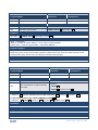
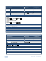
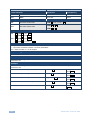
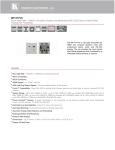
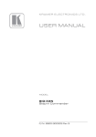
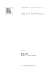
Figure 1 defines the front panel of the WP-577VH.
Figure 1: WP-577VH Wall Plate Front Panel
#
Feature
Function
1
HDMI IN Input Connector
Connect to the HDMI source
2
HDMI Signal LED
Lights green when all the following are true:
The port is selected
There is a valid HDMI signal present
The signal is being routed via the DGKat output
Lights red when any of the following is true:
No signal is connected
The signal is not valid
Routing is not working
WP-577VH - Defining the WP-577VH Wall Plate
7
8
#
Feature
Function
3
PC Graphics Signal LED
Lights green when all the following are true:
The port is selected
There is a valid PC graphics signal present
The signal is being routed via the DGKat output
Lights red when any of the following is true:
No signal is connected
The signal is not valid
Routing is not working
4
ON LED
The LED indicates the following:
Lights green—the device receives adequate power
Lights red—the power is insufficient
5
PC IN Input Connector
Connect to the PC graphics source
6
AUDIO IN 3.5mm Mini
Jack
Connect to the unbalanced, stereo audio source
WP-577VH - Defining the WP-577VH Wall Plate
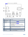
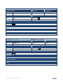
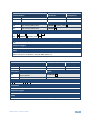
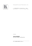
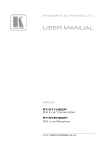
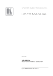
Figure 2 defines the rear panel of the WP-577VH.
Figure 2: WP-577VH Wall Plate Rear Panel
#
Feature
Function
1
CONTROL Connector
For future use
2
AUDIO Out 3-pin
Terminal Block
Connect to the unbalanced, stereo audio acceptor
3
SETUP 8-way
DIP-switch
Sets the device behavior, (see Section 8.1)
4
K-LINK Mode Switch
and LED
Press the switch to toggle between active and passive data modes
for the local RS-232 port, (see Section 6.4).
The LED indicates the following:
Lights green—the device is in active mode, (the wallplate is
being controlled)
Lights red—the device is in passive mode, (the external device
is being controlled)
5
RS-232 3-pin Terminal
Block
Connect to a remote, serial signal source or acceptor (for example,
a PC or a device to be controlled via a serial port).
Note: Serial commands are transmitted even when the video signal
is absent
6
12V DC Connector
Connect to the power adapter
7
Earth Terminal
Connect to the common ground (optional)
8
DGKat OUT RJ-45 TP
Connector
Connect to a compatible DGKat TP switcher or receiver (for
example, VS-62H or TP-578HDCP)
WP-577VH - Defining the WP-577VH Wall Plate
9
5
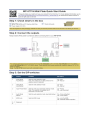
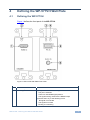
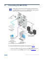
Connecting the WP-577VH
i
Always switch off the power to all devices before connecting them to
your WP-577VH. After connecting your WP-577VH, connect its power
and then switch on the power to the other devices.
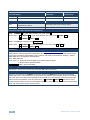
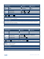
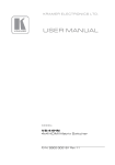
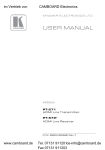
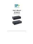
Figure 3: Connecting the WP-577VH Wall Plate
To connect the WP-577VH as illustrated in the example in Figure 3:
1. Connect the DGKat Out RJ-45 connector on the WP-577VH to the Line In
RJ-45 connector on the TP-578H using STP cable (see Section 3.1).
10
WP-577VH - Connecting the WP-577VH
2. Connect the RS-232 3-pin terminal block on the rear of the WP-577VH to a
remote serial device (controller or to be controlled).
3. If not using PowerConnect, connect the power adapter to the WP-577VH
and to the mains electricity (not shown in Figure 3).
4. Connect an HDMI source, (for example, a Blu-ray disk player) to the HDMI
input on the WP-577VH.
5. Connect a VGA source, (for example, a computer graphics source) to the
PC In on the WP-577VH.
6. Connect an unbalanced, stereo audio source, (for example, the audio output
of the laptop) to the Audio In 3.5mm mini jack on the WP-577VH.
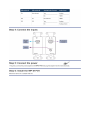
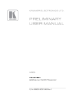
5.1
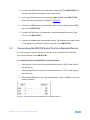
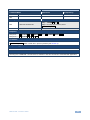
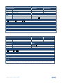
Connecting the RS-232 Serial Port to a Remote Device
You can connect a serial controller or a device to be controlled to the RS-232
3-pin terminal block on the WP-577VH.
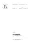
To connect a device to the RS-232 3-pin serial port:
Connect the TX pin on the 3-pin terminal block to pin 2 (RX) on the 9-pin Dsub connector
Connect the RX pin on the 3-pin terminal block to pin 3 (TX) on the 9-pin Dsub connector
Connect the GND pin on the 3-pin terminal block to pin 5 (GND) on the 9-pin
D-sub connector
Figure 4: Connecting the RS-232 Serial Port to a Remote Device
WP-577VH - Connecting the WP-577VH
11
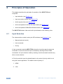
6
Principles of Operation
This chapter describes the principles of operation of the WP-577VH and
comprises:
Input selection (see Section 6.1)
Input connection timeout (see Section 6.2)
Audio signal priority (see Section 6.3)
Active and passive local RS-232 data modes (see Section 6.4)
Active and passive DGKat RS-232 data modes (see Section 6.5)
The WP-577VH selects video and audio inputs based on the following rules.
6.1
Input Selection
The video selection mode is set by the DIP-switches (see Section 8.1) to:
Manual (external control)
Last connected
Priority
In last connected mode the WP-577VH selects the input that was the last to be
connected. In manual mode the input is selected by sending Protocol 3000
commands. An input selection made by sending a serial command overrides any
other current selection.
In Priority mode the input is selected based on the order of priority which is set
using the control application. The default order of priority is:
1. HDMI
2. VGA
12
WP-577VH - Principles of Operation
This priority remains in force until any of the following occurs:
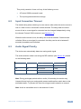
6.2
A Protocol 3000 command is sent
The input signals/connections change
Input Connection Timeout
The default delay when switching to a new source when either the active source is
lost or a new source is connected is three seconds. The delay when the active
source is lost or a new signal is connected can be changed independently using
the relevant Protocol 3000 command, (see Section 11.2).
When the active source is lost, the delay can be set to between 3 seconds and
unlimited. When a new signal is connected, the delay can be set to between 0
seconds (immediate) and unlimited.
6.3
Audio Signal Priority
The device can automatically detect an analog audio signal.
The audio selection mode is set using the DIP-switches (see Section 8.1) based
on the following table.
DIP-switch #1
DIP-switch #4
Analog Audio Present
Audio Used
On
Not relevant
Yes
Analog
No
HDMI
Off
On
Not relevant
HDMI
Off
Off
Yes
Analog
No
Analog (=mute)
Note: During prolonged periods with no audio (10 seconds), the device may
interpret this as having no analog audio present and therefore switch back to the
embedded audio. To prevent this from occurring set audio selection to manual.
Note: Audio is transmitted even in the absence of video.
WP-577VH - Principles of Operation
13
6.4
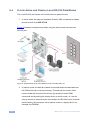
K-Link Active and Passive Local RS-232 Data Modes
The Local RS-232 port can be set to either active or passive mode.
1. In active mode, the data are treated as Protocol 3000 commands and these
provide control of the WP-577VH.
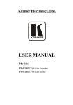
Figure 5 illustrates a sample setup when using the active mode from the local
RS-232 port.
Figure 5: Sample Setup using Active Mode from the Local RS-232 Port
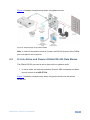
2. In passive mode, the data are treated as raw data and are transmitted over
the DGKat link with no local processing. This data can be used to either
communicate with remote K-link devices (by sending Protocol 3000
commands and by setting the remote device to active mode), or it can be
used to control an external device connected to the RS-232 port of a remote
device (either a K-Link device set to passive mode or a legacy device, for
example, the TP-574).
14
WP-577VH - Principles of Operation
Figure 6 illustrates a sample setup when using passive mode.
Figure 6: Sample Setup using Passive Mode
Note: In order for the passive mode to function, the RS-232 channel of the DGKat
port must also be set to passive.
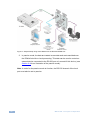
6.5
K-Link Active and Passive DGKat RS-232 Data Modes
The DGKat RS-232 port can be set to either active or passive mode.
1. In active mode, the data are treated as Protocol 3000 commands and these
provide control of the WP-577VH.
Figure 7 illustrates a sample setup when using active mode over the remote
DGKat link.
WP-577VH - Principles of Operation
15
Figure 7: Sample Setup using Active Mode over the Remote DGKat Link
2. In passive mode, the data are treated as raw data and are transmitted over
the DGKat link with no local processing. This data can be used to control an
external device connected to the RS-232 port of a remote K-link device, (see
Section 6.4 for an illustration of the passive mode).
Note: In order for the passive mode to function, the RS-232 channel of the local
port must also be set to passive.
16
WP-577VH - Principles of Operation
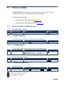
7
Operating the WP-577VH
This chapter describes the operation of the WP-577VH and comprises:
Selecting an input (see Section 6.1)
Selecting active or passive data modes (see Section 7.2)
The WP-577VH selects video and audio inputs based on the rules described
below.
7.1
Selecting an Input
To select an input in Manual mode:
Send a Protocol 3000 serial command selecting the required input, (see
Section 11.2)
7.2
K-Link: Selecting Active or Passive Local RS-232 Data
Mode
To switch between active and passive mode in local RS-232 data mode:
Press the K-Link mode switch on the front panel, (the mode status is
indicated by the K-Link LED)
–OR–
Send the KLINK_INF (active mode)/KLINK_CLS (passive mode) Protocol
3000 command, (the mode status is indicated by the K-Link LED), see
Section 11.2
Note: Protocol 3000 commands from the local RS-232 port need to be at 115200
baud rate , while data can only be sent at up to 9600 baud rate
Note: Data is still transmitted even in the absence of video and audio signals.
Note: In order for the passive mode to function, the RS-232 channel of the local
port must also be set to passive.
WP-577VH - Operating the WP-577VH
17
7.3
Selecting Active or Passive DGKat RS-232 Data Mode
To switch between active and passive modes in DGKat RS-232 data mode:
Send the KLINK_INF (active mode)/KLINK_CLS (passive mode) Protocol
3000 command at 9600, (see Section 11.2)
Note: The mode status is not indicated by the K-Link LED.
Note: In order for the passive mode to function, the RS-232 channel of the local
port must also be set to passive.
18
WP-577VH - Operating the WP-577VH
8
Configuring and Maintaining the WP-577VH
This chapter describes configuring and maintaining the WP-577VH and
comprises:
8.1
Setting the configuration DIP-switch (see Section 6.1)
Updating the firmware (see Section 6.1)
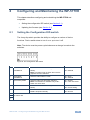
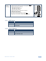
Setting the Configuration DIP-switch
The 4-way dip-switch provides the ability to configure a number of device
functions. Push a switch down to turn it on or up to turn it off.
Note: The device must be power-cycled whenever a change is made to the
switches.
Figure 8: The Configuration DIP-switch
#
Feature
Function
DIP-switch
1
Audio Mode
Auto/Manual
Sets the audio selection mode, (see table
below).
Note: This setting has no effect when the PC
graphics source is selected
On—Auto
Off—Manual
2
Video Mode
Auto/Manual
Sets the video selection mode
On—Auto
Off—Manual
3
Input Priority Mode
Sets the video input automatic selection.
Note: This selection is available only if DIPswitch 2 is set to Auto
On—Priority
Off—Last connected
4
Audio Mode Manual
Sets the audio selection mode, (see table
below)
On—Force embedded
Off—Force analog
5
Lock EDID
Locks the current EDID. When unlocked the
EDID is acquired normally
On—Lock
Off—Unlock
6
7
For future use
8
WP-577VH - Configuring and Maintaining the WP-577VH
19
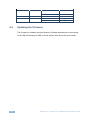
8.2
DIP-switch #1
DIP-switch #4
Analog Audio Present
Audio Used
On
Not relevant
Yes
Analog
No
HDMI
Off
On
Not relevant
HDMI
Off
Off
Yes
Analog
No
Analog (=mute)
Updating the Firmware
The firmware is updated using the Kramer K-Upload software and by connecting
via the RS-232 serial port. Refer to the K-Upload User Guide for more details.
20
WP-577VH - Configuring and Maintaining the WP-577VH
9
Wiring the DGKat TP RJ-45 Connectors
Connect/solder the cable shield to the RJ-45 connector shield.
!
Do not use a crossed TP cable with this product.
Using a TP cable that is incorrectly wired may cause permanent
damage to the device
Do not use unshielded TP cables with this product
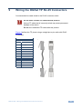
Figure 9 defines the TP pinout using a straight pin-to-pin cable with RJ-45
connectors.
EIA /TIA 568B
PIN
1
Wire Color
Orange / White
2
Orange
3
Green / White
4
Blue
5
Blue / White
6
Green
7
Brown / White
8
Brown
Pair 1
4 and 5
Pair 2
1 and 2
Pair 3
3 and 6
Pair 4
7 and 8
Figure 9: TP Pinout Wiring
WP-577VH - Wiring the DGKat TP RJ-45 Connectors
21
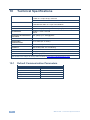
10
Technical Specifications
INPUTS:
1 HDMI on an HDMI connector
1 VGA on a 15-pin HD (F) connector
1 Unbalanced stereo audio on a 3.5mm mini jack
OUTPUT:
1 DGKat TP on an RJ-45 connector
1 Unbalanced audio on a 3-pin Terminal Block
PORTS:
1 Bidirectional serial RS-232 port on a 3-way terminal block
BANDWIDTH:
Up to 4.95Gbps (1.65Gbps bandwidth per graphic channel)
STANDARDS:
HDMI, x.v.Color™ and 3D
HDCP
MAXIMUM TRANSMISSION
DISTANCE:
90m (295ft) up to 1080p @60Hz
POWER CONSUMPTION:
12V DC, 700mA
OPERATING
TEMPERATURE:
0° to +40°C (32° to 104°F)
STORAGE TEMPERATURE:
–40° to +70°C (–40° to 158°F)
HUMIDITY:
10% to 90%, RHL non-condensing
DIMENSIONS:
US: 8.79cm x 4.3cm x 10.47cm (3.46" x 1.69" x 4.12”) W, D, H
WEIGHT:
0.2kg (0.44lbs) approx.
INCLUDED ACCESSORIES:
Power supply
Specifications are subject to change without notice at http://www.kramerelectronics.com
10.1
Default Communication Parameters
RS-232
22
Baud Rate
115,200
Data Bits
8
Stop Bits
1
Parity
None
Command Format
ASCII
WP-577VH - Technical Specifications
11
Protocol 3000
The WP-577VH can be operated using serial commands from a PC, remote
controller or touch screen using the Kramer Protocol 3000.
This section describes the:
11.1
Kramer Protocol 3000 syntax (see Section 11.1)
Kramer Protocol 3000 commands (see Section 11.2)
Kramer Protocol 3000 Syntax
11.1.1
Host Message Format
Start
Address (optional)
Body
Delimiter
#
device_id@
Message
CR
11.1.1.1
Simple Command
Command string with only one command without addressing:
Start
Body
Delimiter
#
Command SP Parameter_1,Parameter_2,…
CR
11.1.1.2
Command String
Formal syntax with commands concatenation and addressing:
Start
Address
Body
Delimiter
#
device_id@
Command_1 Parameter1_1,Parameter1_2,…|
Command_2 Parameter2_1,Parameter2_2,…|
Command_3 Parameter3_1,Parameter3_2,…|…
CR
11.1.2
Device Message Format
Start
Address (optional)
Body
delimiter
~
device_id@
Message
CR LF
11.1.2.1
Device Long Response
Echoing command:
Start
Address (optional)
Body
Delimiter
~
device_id@
Command SP [Param1 ,Param2 …] result
CR LF
CR = Carriage return (ASCII 13 = 0x0D)
LF = Line feed (ASCII 10 = 0x0A)
SP = Space (ASCII 32 = 0x20)
WP-577VH - Protocol 3000
23
11.1.3
Command Terms
Command
A sequence of ASCII letters ('A'-'Z', 'a'-'z' and '-').
Command and parameters must be separated by at least one space.
Parameters
A sequence of alphanumeric ASCII characters ('0'-'9','A'-'Z','a'-'z' and some special
characters for specific commands). Parameters are separated by commas.
Message string
Every command entered as part of a message string begins with a message
starting character and ends with a message closing character.
Note: A string can contain more than one command. Commands are separated by
a pipe ( '|' ) character.
Message starting character
'#' – For host command/query
'~' – For device response
Device ID (Optional, for K-NET)
K-NET Device ID followed by '@'
Query sign
'?' follows some commands to define a query request.
Message closing character
CR – For host messages; carriage return (ASCII 13)
CRLF – For device messages; carriage return (ASCII 13) + line-feed (ASCII 10)
Command chain separator character
When a message string contains more than one command, a pipe ( '|' ) character
separates each command.
Spaces between parameters or command terms are ignored.
24
WP-577VH - Protocol 3000
11.1.4
Entering Commands
You can directly enter all commands using a terminal with ASCII communications
software, such as HyperTerminal, Hercules, etc. Connect the terminal to the serial
or Ethernet port on the Kramer device. To enter CR press the Enter key.
( LF is also sent but is ignored by command parser).
For commands sent from some non-Kramer controllers like Crestron, some
characters require special coding (such as, /X##). Refer to the controller manual.
11.1.5
Command Forms
Some commands have short name syntax in addition to long name syntax to allow
faster typing. The response is always in long syntax.
11.1.6
Chaining Commands
Multiple commands can be chained in the same string. Each command is
delimited by a pipe character (“|”). When chaining commands, enter the message
starting character and the message closing character only once, at the
beginning of the string and at the end.
Commands in the string do not execute until the closing character is entered.
A separate response is sent for every command in the chain.
11.1.7
Maximum String Length
64 characters
WP-577VH - Protocol 3000
25
11.2
26
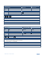
Kramer Protocol 3000 Commands
Command
Description
#
Protocol handshaking
AV
Switch audio and video
AV-SW-MODE
Set auto switch mode
AV-SW-TIMEOUT
Set auto switching timeout
BUILD-DATE?
Read device build date
CPEDID
Copy EDID data from the output to the input
DIR
List files in device
DISPLAY
Valid / Invalid output
FACTORY
Reset to factory default configuration
FS-FREE?
Get file system free space
GEDID
Read EDID data
HDCP-MOD?
Get HDCP mode
HDCP-STAT?
Get HDCP signal status
HELP
Get command list
KLINK_CLS
Set K-Link data mode
KLINK_INF
Set K-Link MCU direct mode
LDEDID
Write EDID data to input
LDFW
Load new firmware
LOAD
Load new Transwitch firmware
MODEL?
Read device model
NAME
Set machine (DNS) name
NAME-RST
Reset machine name to factory default (DNS)
PRIO?
Get input priority
PRIORITY
Set priority for all channels
PROT-VER?
Get device protocol version
RESET
Reset device
SECUR
Set current security state
SIGNAL
Valid / Invalid input
SN?
Read device serial number
VERSION?
Read device firmware version
VID
Switch video only
WP-577VH - Protocol 3000
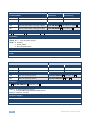
Command - #
Command Type - System-mandatory
Command Name
Permission
Transparency
Set:
#
End User
Public
Get:
-
-
-
Description
Syntax
Set:
Protocol handshaking
#␍
Get:
-
-
Response
~nn@␠OK␍␊
Parameters
Response Triggers
Notes
Use to validate the Protocol 3000 connection and get the machine number
Command - AV
Command Name
Command Type - Switch
Permission
Transparency
Set:
AV
End User
Public
Get:
-
-
-
Description
Set:
Syntax
Switch audio and video
#AV␠in>out, in>out,…␍
Get:
Response
~nn@AV␠in>out, in>out,…␍␊
Parameters
in - input number or '0' to disconnect output
> - connection character between in and out parameters
out - output number or '*' for all outputs
Response Triggers
Notes
WP-577VH - Protocol 3000
27
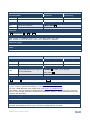
Command - AV-SW-MODE
Command Type - System
Command Name
Permission
Transparency
Set:
AV-SW-MODE
End user
Public
Get:
AV-SW-MODE?
End user
Public
Description
Syntax
Set:
Set input auto switch mode (per output)
# AV-SW-MODE␠layer,output_id, mode␍
Get:
Get input auto switch mode (per output)
# AV-SW-MODE?␠layer,output_id␍
Response
~ nn@AV-SW-MODE␠layer,output_id, mode␍␊
Parameters
layer
output_id - 1….num of system outputs
mode - 0 - manual
1 - priority switch
2 - last connected switch
Response Triggers
Notes
Command - AV-SW-TIMEOUT
Command Name
Command Type - System
Permission
Transparency
Set:
AV-SW-TIMEOUT
End User
Public
Get:
AV-SW-TIMEOUT?
End User
Public
Description
Syntax
Set:
Set auto switching timeout
#AV-SW-TIMEOUT␠action,time_out ␍
Get:
Get auto switching timeout
#AV-SW-TIMEOUT?␠action ␍
Response
~ nn@AV-SW-TIMEOUT␠action,time_out ␍
Parameters
action 0 - on video signal loss timeout
1 - on new video signal detected switch timeout
timeout - timeout in seconds
Response Triggers
Notes
28
WP-577VH - Protocol 3000
Command - BUILD-DATE
Command Type - System-mandatory
Command Name
Permission
Transparency
Set:
-
-
-
Get:
BUILD-DATE?
End User
Public
Description
Syntax
Set:
Get device build date
#BUILD-DATE␍
Get:
-
-
Response
~nn@BUILD-DATE␠date␠time␍␊
Parameters
date - Format: YYYY/MM/DD where YYYY = Year, MM = Month, DD = Day
time - Format: hh:mm:ss where hh = hours, mm = minutes, ss = seconds
Response Triggers
Notes
Command - CPEDID
Command Name
Command Type - System
Permission
Transparency
Set:
CPEDID
End User
Public
Get:
-
-
-
Description
Syntax
Set:
Copy EDID data from the output to
the input EEPROM
#CPEDID␠src_type, src_id, dst_type,
Get:
-
-
dest_bitmap␍
Response
~nn@CPEDID␠src_stg, src_id, dst_type, dest_bitmap␍␊
Parameters
src_type - EDID source type (usually output) (see Section 11.2.1 EDID Source)
src_id - number of chosen source stage (1.. max number of inputs/outputs)
dst_type - EDID destination type (usually input) (see Section 5.12 EDID Source)
dest_bitmap - bitmap representing destination IDs. Format: XXXX…X, where X is hex digit. The binary
form of every hex digit represents corresponding destinations. Setting ‘1’ says that EDID data has to be
copied to this destination
Response Triggers
Response is sent to the com port from which the Set was received (before execution)
Notes
Destination bitmap size depends on device properties (for 64 inputs it is a 64-bit word)
Example: bitmap 0x0013 means inputs 1,2 and 5 are loaded with the new EDID
WP-577VH - Protocol 3000
29
Command - DIR
Command Type - File System
Command Name
Permission
Transparency
Set:
DIR
Administrator
Public
Get:
-
-
-
Description
Syntax
Set:
List files in device
#DIR␍
Get:
-
-
Response
Multi Line:
~nn@DIR␍␊
file_name TAB file_size␠bytes,␠ ID:␠file_id␍␊
TABfree_size␠bytes.␍␊
Parameters
file_name - name of file
file_size - file size in bytes. A file can take more space on device memory
file_id - internal ID for file in file system
free_size - free space in bytes in device file system
Response Triggers
Notes
Command - DISPLAY?
Command Type - System
Command Name
Permission
Transparency
Set:
-
-
-
Get
DISPLAY?
End User
Public
Description
Syntax
Set:
-
-
Get:
Get output HPD status
#DISPLAY?␠out_id␍
Response
~ nn@DISPLAY ␠out_id,status ␍␊
Parameters
out_id - output number
status - HPD status according to signal validation
Response Triggers
After execution, response is sent to the com port from which the Get was received
Response is sent after every change in output HPD status ON to OFF
Response is sent after every change in output HPD status OFF to ON and ALL parameters (new
EDID, etc.) are stable and valid
Notes
30
WP-577VH - Protocol 3000
Command - FACTORY
Command Type - System-mandatory
Command Name
Permission
Transparency
Set:
FACTORY
End User
Public
Get:
-
-
-
Description
Syntax
Set:
Reset device to factory default
configuration
#FACTORY␍
Get:
-
-
Response
~nn@FACTORY␠OK␍␊
Parameters
Response Triggers
Notes
This command deletes all user data from the device. The deletion can take some time.
Command - FS-FREE?
Command Type - File System
Command Name
Permission
Transparency
Set:
-
-
-
Get:
FS-FREE?
Administrator
Public
Description
Syntax
Set:
-
-
Get:
Get file system free space
#FS-FREE?␍
Response
~nn@FS_FREE␠free_size␍␊
Parameters
free_size - free size in device file system in bytes
Response Triggers
Notes
WP-577VH - Protocol 3000
31
Command - GEDID
Command Type - System
Command Name
Permission
Transparency
Set:
GEDID
Administrator
Public
Get:
GEDID?
End User
Public
Description
Syntax
Set:
Set EDID data from device
#GEDID␠stage, stage_id ␍
Get:
Get EDID support on certain input/output
#GEDID?␠stage, stage_id ␍
Response
Set:
Multi-line response:
~nn@GEDID␠stage,stage_id,size␍␊
EDID_data␍␊
~nn@GEDID␠stage,stage_id␠OK␍␊
Get:
~nn@GEDID␠stage,stage_id,size␍␊
Parameters
stage - input/output (see Section 11.2.1 EDID Source)
stage_id - number of chosen stage (1.. max number of inputs/outputs)
size - EDID data size. For Set, size of data to be sent from device, for Get, 0 means no EDID support
Response Triggers
Response is sent to the com port from which the Set (before execution) / Get command was received
Notes
For Get, size=0 means EDID is not supported
For old devices that do not support this command, ~nn@ ERR 002␍␊ is received
32
WP-577VH - Protocol 3000
Command - HDCP-MOD
Command Type - System
Command Name
Permission
Transparency
Set:
HDCP-MOD
Administrator
Public
Get:
HDCP-MOD?
End User
Public
Description
Syntax
Set:
Set HDCP mode
#HDCP-MOD ␠ inp_id,mode ␍
Get:
Get HDCP mode
#HDCP-MOD?␠ stage_id ␍
Response
Set / Get: ~ nn@HDCP-MOD␠stage_id,mode ␍␊
Parameters
inp_id - input number (1.. max number of inputs)
mode - HDCP mode
Response Triggers
Response is sent to the com port from which the Set (before execution) / Get command was received
Response is sent to all com ports after execution if HDCP-MOD was set by any other external control
device (button press, device menu and similar) or HDCP mode changed
Notes
Set HDCP working mode on the device input:
HDCP supported - HDCP_ON [default]
HDCP not supported - HDCP OFF
HDCP support changes following detected sink - MIRROR OUTPUT
WP-577VH - Protocol 3000
33
Command - HDCP-STAT
Command Type - System
Command Name
Permission
Transparency
Set:
-
-
-
Get:
HDCP-STAT?
End User
Public
Description
Syntax
Set:
None
-
Get:
Get HDCP signal status
#HDCP-STAT?␠stage,stage_id␍
Response
Set / Get: ~ nn@HDCP-STAT␠stage,stage_id,mode␍␊
Parameters
stage – input/output
stage_id - number of chosen stage (1.. max number of inputs/outputs)
actual_status - signal encryption status - valid values ON/OFF
Response Triggers
Response is sent to the com port from which the Set (before execution) / Get command was received
Response is sent to all com ports after execution if HDCP-STAT was set by any other external control
device (button press, device menu and similar) or HDCP mode changed
Notes
Command - HELP
Command Name
Command Type - System-mandatory
Permission
Transparency
Set:
-
-
-
Get:
HELP
End User
Public
Description
Syntax
Set:
-
Get:
Get command list or help for specific
command
2 options:
1. #HELP␍
2. #HELP␠command_name␍
Response
1. Multi-line: ~nn@Device available protocol 3000 commands:␍␊command,␠command…␍␊
To get help for command use: HELP (COMMAND_NAME)␍␊
2. Multi-line: ~nn@HELP␠command:␍␊description␍␊USAGE:usage ␍␊
Parameters
Response Triggers
Notes
34
WP-577VH - Protocol 3000
Command – KLINK_INF
Command Type – System
Command Name
Permission
Transparency
Set:
KLINK_INF
Admin
Internal
Get:
-
-
-
Description
Syntax
Set:
Set K-Link MCU direct mode (DGKat
only)
#KLINK_INF␍
Get :
-
-
Response
KLNK_ACK␍␊
Parameters
None
Response Triggers
After receiving KLINK_INF command over DGKat/local RS-232
Notes
Command – KLINK_CLS
Command Type – System
Command Name
Permission
Transparency
Set:
KLINK_CLS
Admin
Internal
Get:
-
-
-
Description
Syntax
Set:
Set K-Link data mode (DGKat only)
#KLINK_CLS␍
Get:
-
-
Response
KLNK_ACK␍␊
Parameters
None
Response Triggers
Under receiving KLINK_CLS command over DGKat/RS-232
Notes
WP-577VH - Protocol 3000
35
Command - LDEDID
Command Name
Command Type - System
Permission
Transparency
Set:
LDEDID
End User
Public
Get:
-
-
-
Description
Syntax
Set:
Write EDID data from external
application to device
Multi-step syntax (see following steps)
Get:
None
None
Communication Steps (Command and Response)
Step 1: #LDEDID␠dst_type, dest_bitmask, size, safe_mode␍
Response 1: ~nn@LDEDID␠dst_type, dest_bitmask, size, safe_mode␠READY␍␊ or
~nn@LDEDID␠ERRnn␍␊
Step 2: If ready was received, send EDID_DATA
Response 2: ~ nn@LDEDID ␠dst_type, dest_bitmask, size, safe_mode␠ OK␍␊ or
~nn@LDEDID␠ERRnn␍␊
Parameters
dst_type - EDID destination type (usually input) (see Section 11.2.1 EDID Source)
dest_bitmask - bitmap representing destination IDs. Format: 0x********, where * is ASCII presentation
of hex digit. The binary presentation of this number is a bit mask for destinations. Setting ‘1’ means
EDID data has to be copied to this destination
size - EDID data size
safe_mode - 0 - Device accepts the EDID as is without trying to adjust
1 - Device tries to adjust the EDID
EDID_DATA - data in protocol packets
Response Triggers
Response is sent to the com port from which the Set (before execution)
Notes
When the unit receives the LDEDID command it replies with READY and enters the special EDID
packet wait mode. In this mode the unit can receive only packets and not regular protocol commands.
If the unit does not receive correct packets for 30 seconds or is interrupted for more than 30 seconds
before receiving all packets, it sends timeout error ~nn@LDEDID␠ERR01␍␊ and returns to the
regular protocol mode. If the unit received data that is not a correct packet, it sends the corresponding
error and returns to the regular protocol mode.
36
WP-577VH - Protocol 3000
Command - LDFW
Command Name
System - Packets
Permission
Transparency
Set:
LDFW
Internal SW
Public
Get:
-
-
-
Description
Syntax
Set:
Load new firmware file
Step 1: #LDFW␠size␍
Step 2: If ready was received, send
FIRMWARE_DATA
Get:
-
-
Response
Response 1: ~nn@LDFW␠size␠READY␍␊ or ~nn@LDFW␠ERRnn␍␊
Response 2: ~nn@LDFW␠size␠OK␍␊
Parameters
size - size of firmware data that is sent
FIRMWARE_DATA - HEX or KFW file in protocol packets (see Section 4)
Response Triggers
Notes
In most devices firmware data is saved to flash memory, but the memory does not update until
receiving the “UPGRADE” command and is restarted. Use this command in dedicated SW application
WP-577VH - Protocol 3000
37
Command - LOAD
Command Type - System - Packets
Command Name
Permission
Transparency
Set:
LOAD
Administrator
Public
Get:
-
-
-
Description
Syntax
Set:
Load file to device
#LOAD␠file_name,size␍
Get:
-
-
Response
Data sending negotiation:
* Device ~01@LOAD␠file_name,size␠READY␍␊
* End User (+Device)Send file in Protocol Packets
* Device ~01@LOAD␠file_name, size␠OK␍␊
Parameters
file_name - name of file to save on device
size - size of file data that is sent.
Response Triggers
Notes
Command - MODEL?
Command Name
Command Type - System-mandatory
Permission
Transparency
Set:
-
-
-
Get:
MODEL?
End User
Public
Description
Syntax
Set:
-
-
Get:
Get device model
#MODEL?␍
Response
~nn@MODEL␠model_name␍␊
Parameters
model_name - String of up to 19 printable ASCII chars
Response Triggers
Notes
38
WP-577VH - Protocol 3000
Command - NAME
Command Type - System (Ethernet)
Command Name
Permission
Transparency
Set:
NAME
Administrator
Public
Get:
NAME?
End User
Public
Description
Syntax
Set:
Set machine (DNS) name
#NAME␠machine_name␍
Get:
Get machine (DNS) name
#NAME?␍
Response
Set: ~nn@NAME␠machine_name␠OK␍␊
Get: ~nn@NAME?␠machine_name␍␊
Parameters
machine_name - String of up to 14 alpha-numeric chars (can include hyphen, not at the beginning or
end)
Response Triggers
Notes
The machine name is not the same as the model name. The machine name is used to identify a
specific machine or a network in use (with DNS feature on)
Command - NAME-RST
Command Name
Command Type - System (Ethernet)
Permission
Transparency
Set:
NAME-RST
Administrator
Public
Get:
-
-
-
Description
Syntax
Set:
Reset machine (DNS) name to
factory default
#NAME-RST␍
Get:
-
-
Response
~nn@NAME-RST␠OK␍␊
Parameters
Response Triggers
Notes
Factory default of machine (DNS) name is “KRAMER_” + 4 last digits of device serial number
WP-577VH - Protocol 3000
39
Command - PRIO
Command Type - System
Command Name
Permission
Transparency
Set:
PRIO
Administrator
Public
Get
PRIO?
Administrator
Public
Description
Syntax
Set:
Set input priority
#PRIO␠input_id,prio␍
Get:
Get input priority
#PRIO?␠input_id ␍
Response
~ nn@PRIO ␠input_id,prio␍␊
Parameters
input_id - window number setting new source
prio - assigned priority (1.. max priority)
Response Triggers
After execution, response is sent to the com port from which the Set/Get was received
After execution, response is sent to all com ports if PRIO was set by any other external control device
(button press, device menu and similar)
Notes
The PRIO max value may vary for different devices
Command - PRIORITY
Command Type - System
Command Name
Permission
Transparency
Set:
PRIORITY
Administrator
Public
Get:
PRIORITY?
Administrator
Public
Description
Syntax
Set:
Set input priority
Get:
Get input priority
# PRIORITY␠layer,PRIORITY1, PRIORITY2…
PRIORITYn ␍
# PRIORITY?layer ␍
Response
~ nn@ PRIORITY␠layer,PRIORITY1, PRIORITY2… PRIORITYn ␍␊
Parameters
layer
PRIORITY1 - priority of first input
PRIORITYn- priority of input n
Response Triggers
Notes
WP-577VH – layer parameter is not used
40
WP-577VH - Protocol 3000
Command - PROT-VER?
Command Name
Command Type - System-mandatory
Permission
Transparency
Set:
-
-
-
Get:
PROT-VER?
End User
Public
Description
Syntax
Set:
-
-
Get:
Get device protocol version
#PROT-VER?␍
Response
~nn@PROT-VER␠3000:version␍␊
Parameters
Version - XX.XX where X is a decimal digit
Response Triggers
Notes
Command - RESET
Command Name
Command Type - System-mandatory
Permission
Transparency
Set:
RESET
Administrator
Public
Get:
-
-
-
Description
Syntax
Set:
Reset device
#RESET␍
Get:
-
-
Response
~nn@RESET␠OK␍␊
Parameters
Response Triggers
Notes
To avoid locking the port due to a USB bug in Windows, disconnect USB connections immediately after
running this command. If the port was locked, disconnect and reconnect the cable to reopen the port.
WP-577VH - Protocol 3000
41
Command - SECUR
Command Type - Authentication
Command Name
Permission
Transparency
Set:
SECUR
Administrator
Public
Get:
SECUR?
Not Secure
Public
Description
Syntax
Set:
Start/stop security
#SECUR␠security_mode␍
Get:
Get current security state
#SECUR?␍
Response
Set: ~nn@SECUR␠security_mode␠OK ␍␊
Get: ~nn@SECUR␠security_mode ␍␊
Parameters
security_mode – 1/ON - enables security, 0/OFF - disables security
Response Triggers
Notes
The permission system works only if security is enabled with the “SECUR” command
Command - SIGNAL
Command Type - System
Command Name
Permission
Transparency
Set:
-
-
-
Get
SIGNAL?
End User
Public
Description
Syntax
Set:
-
-
Get:
Get input signal lock status
#SIGNAL?␠inp_id␍
Response
~ nn@SIGNAL ␠ inp_id,status ␍␊
Parameters
inp_id - input number
status - lock status according to signal validation
Response Triggers
After execution, a response is sent to the com port from which the Get was received
Response is sent after every change in input signal status ON to OFF, or OFF to ON
Notes
42
WP-577VH - Protocol 3000
Command - SN?
Command Name
Command Type - System-mandatory
Permission
Transparency
Set:
-
-
-
Get:
SN?
End User
Public
Description
Syntax
Set:
-
-
Get:
Get device serial number
#SN?␍
Response
~nn@SN␠serial_number␍␊
Parameters
serial_number - 11 decimal digits, factory assigned
Response Triggers
Notes
For new products with 14 digit serial numbers, use only the last 11 digits
Command - VERSION?
Command Name
Command Type - System-mandatory
Permission
Transparency
Set:
-
-
-
Get:
VERSION?
End User
Public
Description
Syntax
Set:
-
-
Get:
Get firmware version number
#VERSION?␍
Response
~nn@VERSION␠firmware_version␍␊
Parameters
firmware_version - XX.XX.XXXX where the digit groups are: major.minor.build version
Response Triggers
Notes
WP-577VH - Protocol 3000
43
Command - VID
Command Name
Command Type - Switch
Permission
Transparency
Set:
VID
End User
Public
Get:
VID?
End User
Public
Description
Syntax
Set:
Set video switch state
Get:
Get video switch state
#VID␠in>out, in>out,…␍
#VID?␠out␍
#VID?␠ * ␍
Response
Set: ~nn@VID␠in>out ␍␊
~nn@VID␠in>out ␍␊ …
Get: ~nn@VID␠in>out ␍␊
~nn@VID␠in>1, in>2, … ␍␊
Parameters
in - input number or '0' to disconnect output
> - connection character between in and out parameters
out - output number or '*' for all outputs
Response Triggers
Notes
When AFV switching mode is active, this command also switches audio and the unit replies with
command ~AV.
Examples
When AFV switching mode is active, this command also switches audio and the unit replies with
command ~AV.
Switch video and audio input 3 to output 7
#AV 3>7CR
~01@AV
3>7CRLF
Switch video input 2 to output 4
#V 2>4CR
~01@VID
2>4CRLF
Switch video input 4 to output 2 in machine 6
#6@VID 4>2CR
~06@VID
4>2CRLF
Disconnect video and audio output 4
#AV 0>4CR
~01@AV
0>4CRLF
Switch video input 3 to all outputs
#V 3>* CR
~01@VID 3>*
CRLF
44
WP-577VH - Protocol 3000
Chaining
multiple
commands
11.2.1
11.2.2
#AV 1>* | V 3>4, 2>2, 2>1, 0>2 | V 3>9 | A 0>1 | V? * CR
1. Switch audio and video from input 1 to all outputs
2. Switch video input 3 to output 4,
video input 2 to output 2,
video input 2 to output 1 and
disconnect video output 2
3. Switch video input 3 to output 9 (non-existent)
4. Disconnect audio output 1
5. Get status of all video links
Command processing begins after entering CR
A response is sent for each command after processing
~AV 1>*CRLF
~VID 3>4 CRLF
~VID 2>2 CRLF
~VID 2>1 CRLF
~VID 0>2 CRLF
~VID ERR003
CRLF
~AUD 0>1CRLF
~VID 2>1, 0>2,
1>3, 3>4 CRLF
EDID Source
Number
Value
0
Input
1
Output
2
Default EDID
Signal Validation
Number
Value
0
Signal or sink is not valid
1
Signal or sink is valid
2
Sink and EDID is valid
WP-577VH - Protocol 3000
45
For the latest information on our products and a list of Kramer distributors, visit
our Web site where updates to this user manual may be found.
We welcome your questions, comments, and feedback.
Web site: www.kramerelectronics.com
E-mail: [email protected]
!
P/N:
SAFETY WARNING
Disconnect the unit from the power
supply before opening and servicing
2900- 300311
Rev: 2