1
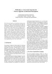
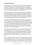
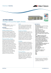
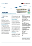
GFK - 1884 J1320-G003 Rev 2.5 June 2002, Firmware Build 127 Series Six Parallel I/O Interface Series Six Parallel I/O Interface Module (S6PIO) Features • I/O Interface specifications similar to IC600BF900C I/O Transmitter module. • Asynchronous scanning runs in parallel with host program logic execution. • Supports normal or expanded channel scanning. • Each S6PIO module supports up to 8 channels, (8000 inputs and 8000 outputs). • Bus length of up to 2000’ made up of 4x500’ segments. • Will drive up to 10 Series Six I/O racks in series. • DMA window mode supported to emulated Series Six memory tables. • Two front panel DB37 connectors, connects to Series Six Parallel I/O Bus. S6PIO BRDOK CHAIN PARITY ISOK ACTIVE RESET CONSOLE U P S T • Failsafe bus operation. • 1,500 volts dielectric isolation. • Front panel RJ11 RS232 serial console port for configuration and debugging. • Six front panel status LED’s. • Supports passive mode operation. Allows monitoring of the I/O in an existing Series Six system. • Redundancy configurations supported through use of passive mode and user application program logic. • Onboard Flash may be upgraded in the field. D • Software configuration, (no DIP switches or jumpers) apart from bus termination when used in a 90-70 PLC system. O R E A M W N Functions S T This Series Six Parallel I/O Interface (S6PIO) module provides an interface between GE Fanuc 90-70 PLC systems and the GE Fanuc Series Six Parallel I/O bus. The S6PIO module allows users to update their existing Series Six installations without having to replace all of the installed I/O. R E A M rtc Figure 1 - Module front View Real Time Consultants Pty Ltd PO Box 688 Mornington Victoria, 3931, AUSTRALIA Page: 1 Email: [email protected] Series Six Parallel I/O Interface GFK - 1884 J1320-G003 Rev 2.5 June 2002, Firmware Build 127 Series Six Parallel I/O Interface Module (S6PIO) Installation Series Six I/O Bus Attachment • Installation should not be attempted without referring to the S6PIO User Manual and the applicable Programmable Controller Installation Manual. • Make sure rack power is off. • Install in any slot of rack 0 or a local expansion rack, (except for slot 1). • Connect the applicable Series Six I/O bus cable or cables depending on the required configuration of the I/O bus. Refer to the Series Six Plus Programmable Controller User Manual for details on how a Series Six I/O chain may be configured. Depending on configuration of the Series Six Plus system, a number of scenarios are possible. 1. Single chain originating from the Series Six Plus I/O Control module. 2. As per item 1 plus a second chain originating from the Auxiliary I/O module. 3. Expanded channels originating from the CPU or downstream I/O racks via I/O transmitter modules configured for expanded mode operation. When replacing the I/O chains, a rule of thumb is to use an S6PIO module for each chain originated from the Series Six CPU rack. • Turn on power. An example of a Master mode application with an S6PIO module originating the I/O chain is shown in Figure 2. An example of a Passive mode application with a Series Six CPU as the Master and the S6PIO module daisy chained within the I/O chain as shown in Figure 3. Up to four S6PIO modules may be installed in a given 90-70 CPU rack or local expansion rack. I/O Bus Termination SERIES 6 CPU RACK The module as shipped has bus terminations fitted for operation at the beginning of the I/O chain. If it is desired to daisy chain the module in the middle of the chain (for example in passive mode configuration), these jumper positions must be moved. Refer to the S6PIO User Manual for more details. A U X C C M 3 I O C L O G I C A R I T H L O G I C M E M O R Y C O N T R O L C O N T R O L P/S I O C VME RACK P/S VME RACK C P U P/S C P U S 6 P I O S 6 P I O S 6 P I O S 6 P I O SERIES SIX AUXILIARY I/O SERIES SIX AUXILIARY I/O SERIES SIX MAIN I/O SERIES SIX MAIN I/O P/S P/S P/S I O R I O T I O R I O T To other Auxiliary I/O racks Max Total 50 feet To Expanded I/O racks Max Total 500 feet To other Main I/O racks Max Total 50 feet To Expanded I/O racks Max Total 500 feet P/S I O R I O T I O R I O T To other Auxiliary I/O racks Max Total 50 feet To Expanded I/O racks Max Total 500 feet To other Main I/O racks Max Total 50 feet To Expanded I/O racks Max Total 500 feet Figure 3 - Example of Passive Mode configuration Figure 2 - Example of Master Mode configuration Real Time Consultants Pty Ltd PO Box 688 Mornington Victoria, 3931, AUSTRALIA Page: 2 Email: [email protected] Series Six Parallel I/O Interface GFK - 1884 J1320-G003 Rev 2.5 June 2002, Firmware Build 127 Series Six Parallel I/O Interface Module (S6PIO) 1 2 3 FWE Enabled JP1 JP2 JP3 Default Jumper Positions JP4 Not Mounted 1 T xD GND 1 2 RxD 13 1 2 3 Termination ON ON JP29 JP5 JP6 JP7 JP8 14 JP26 JP25 1 2 3 0 1 JP30 20 1 2 3 ON JP24 RQ3Z RQ2Z RQ1Z RQ0Z 19 JP34 1 2 3 ON JP23 2 1 1 2 3 ON JP22 1 2 3 ON JP21 ON 1 2 3 JP20 14 13 JP18 JP28 T CK T DI GND T DO T MS T CK T DI GND T DO T MS IACIN/OUT Enabled ON 1 2 3 JP19 2 1 JP27 2 1 1 2 3 JP32 JP35 ON 3 8 4 JP33 1 1 2 3 ON JP17 ON 1 2 3 JP15 ON 1 2 3 JP14 JP9 19 20 SYSFAIL ON 1 2 3 JP16 1 2 JP31 1 2 3 ON JP13 ON 1 2 3 JP12 1 2 3 ON JP11 JP10 Figure 4 - S6PIO Module showing Jumpers in “As Shipped” position. Real Time Consultants Pty Ltd PO Box 688 Mornington Victoria, 3931, AUSTRALIA Page: 3 Email: [email protected] GFK - 1884 J1320-G003 Rev 2.5 June 2002, Firmware Build 127 Jumper Settings Refer to Figure 4 for the locations of onboard jumpers. The S6PIO module is shipped with all jumpers set for plug and play mode in a 90-70 PLC and the I/O bus terminated. These settings are correct for the majority of applications. Jumpers JP1, JP2 and JP3 Microcontroller Mode Selection. These are factory set and cannot be changed. Factory default positions: Series Six Parallel I/O Interface Series Six Parallel I/O Interface Module (S6PIO) VME Configuration from FLASH Mode This mode is intended to be used when the S6PIO module is installed in a standard VME system. The VME slave address and address modifier are programmed into onboard FLASH memory during module configuration prior to first use. • JP5 1 • JP6 1 VME Disabled Mode In this mode the VME bus is disabled. • JP1 2-3 • JP2 1-2 • JP5 0 1-2 • JP6 1 • JP3 On revision 2.00 and later boards these jumpers are not physically fitted. Boot From FLASH or RAM Jumper JP4 – FLASH Memory Protect FLASH memory protect jumper. This jumper is set to the disabled position in the factory and should not be moved unless field upgrading the on board FLASH memory. JP7 specifies whether to boot from a program in FLASH or RAM. This mode is only used during module testing. The factory default position is to boot from FLASH. Jumpers JP5, JP6, JP7 and JP8 - Configuration Configuration jumpers JP5 & JP6 specify the JP5 configuration mode for the module. The JP6 JP7 diagram at left shows the default settings JP8 (1,0,1,1 from top) 0 1 Plug & Play Mode This is the factory default position. In this mode the S6PIO module automatically senses the slot number into which it is plugged and configures its VME slave interface according to the slot number. Refer to the S6PIO User Manual for details of the actual slave interface address and address modifiers. This mode is the normal mode of operation for a 90-70 PLC system. • JP5 1 • JP6 0 Manufacturing Test Mode In this mode the S6PIO module continually runs manufacturing self-tests. The progress of the self-tests is indicated on the front panel LED’s. Refer to the S6PIO User Manual for more details. • JP5 0 • JP6 0 Real Time Consultants Pty Ltd PO Box 688 Mornington Victoria, 3931, AUSTRALIA Position 1 Boot from FLASH Boot Into Onboard Monitor JP8 specifies whether to boot into a monitor program for diagnostic and testing purposes or the application program. The factory default is to boot into the application program. • Position 0 Boot into monitor program • Position 1 Boot application program Jumper JP9 – VME SYSFAIL Diagram at left shows SYSFAIL enabled (normal position) move jumper to top two pins to disable SYSFAIL. JP9 SYSFAIL JP4 Position 0 Boot from RAM • Jumpers JP10 through JP25 - Bus Termination These jumpers are Series Six Bus termination jumpers. In the default position pins 1 to 2 are JP10 jumpered to terminate all signals on the two DB37 connectors with 150ohm resistors. This is the setting when the module is in master mode, and is at the start of an I/O chain, with only one Series Six I/O cable plugged into a DB37 connector (generally the bottom one). Jumpers JP10 through JP25 should be placed in pins 2 to 3 position when the module is used in passive mode, where the module is not at the beginning of an I/O chain. That is when there are Series Six I/O bus cables plugged into both DB37 connectors. Jumpers JP10 through JP25 should also be placed in pins 2 to 3 position if the external 150ohm terminator plug is used. 1 2 3 Diagram at left shows jumper in disabled position ON FWE Enabled • Page: 4 Email: [email protected] GFK - 1884 J1320-G003 Rev 2.5 June 2002, Firmware Build 127 2 1 14 13 IACIN/OUT Enabled Jumper JP32 – IACKIN/OUT Daisy Chain Positions 1 to 2 and 3 to 4 to bypass the IACK daisy chain Positions 1 to 3 and 2 to 4 to enable the IACK daisy chain. 4 2 1 3 The diagram at left shows the chain JP32 bypassed. JP33 Header JP33 – I/O Bus Test Signals Header JP33 makes certain I/O test signals available. This is useful for troubleshooting purposes. 2 – ADS, address strobe 4 – IS, input strobe 6 – CP, card present 8 – PE, parity error 10 – PAR, bus parity Status Indications The six green LED’s at the top of the module provide status information as shown in Table 1. During module initialization all LED’s are cycled twice by an LED test routine. During manufacturing test mode, these LED’s assume special functions. Refer to the S6PIO User Manual for details. LED BRDOK CHAIN PARITY Series Six Parallel I/O Interface Series Six Parallel I/O Interface Module (S6PIO) This LED is turned on for 200msec whenever a command is given to the S6PIO over the VME Bus. RESET RST LED. In Master Mode this LED is on if RST is NOT asserted. When RST is asserted this LED flashes. In passive mode, this LED is off. Table 1 - LED Indicators Console Port The console port is an RJ-11 RS232 port. The pin out connections for this port are shown in Table 2. This pin out is compatible with the GE Fanuc Station Manager Cable IC693CBL316B that may be used to connect to a standard PC DB9 serial port. Console port communication speed is 57600 baud. The console port is designed to be used with a windows 98/NT based console program. The user may use this program to reprogram onboard FLASH memory or to retrieve I/O chain alarms. Refer to the S6PIO User Manual for details. RJ-11 Pin Signal 1 CTS 2 TD Description 3 SG Board OK. Initial state after RESET is off. After configuration is complete and the module is ready for operation the LED shall be on. 4 5 6 RTS Chain OK. (CHOK) This LED is on if power is on at all downstream stations and continuity is OK to all upstream points. If any of these conditions are not met the LED will be off. Chain Parity (CHPAR). The LED is on if output parity is OK at all downstream stations and off if there is an output parity error at one or more stations. The LED state is based on the condition of the bus parity signal and will flicker during DMA cycles (in passive mode) as the parity bus signal line is used for another purpose during DMA windows. ISOK Isolated Power LED. This LED is on if the output voltage of the isolated +5V DC-DC converter is within tolerance and the isolated interface is operational. ACTIVE Command Handler active (CHACT) Real Time Consultants Pty Ltd PO Box 688 Mornington Victoria, 3931, AUSTRALIA RJ-11 Port Pin Description DB9 Pin Signal Clear to send (i/p) 7 RTS Transmitted data (o/p) 2 RD Signal ground 5 SG SG Signal ground 5 SG RD Received data (i/p) 3 TD Request to send (o/p) 8 CTS Table 2 – Console Connections DB37 Male Port A male DB37 port provides for a connection to an upstream Series Six I/O Bus. If an upstream connection is not required, this port should be left unconnected. In this case termination jumpers must be fitted on the board. DB37 Female Port A female DB37 port provides for a connection to a downstream Series Six I/O Bus. If a downstream connection is not required, this port should be left unconnected. In this case termination jumpers must be fitted on the board. Page: 5 Email: [email protected] Series Six Parallel I/O Interface GFK - 1884 Series Six Parallel I/O Interface Module (S6PIO) J1320-G003 Rev 2.5 June 2002, Firmware Build 127 C Blocks The 90-70 PLC interface software is in the form of a collection of C Blocks. The C blocks provide the interface between the 90-70 PLC application program and the S6PIO module. At the completion of processing a C block returns a comprehensive status to the user program. Name Description S6SCAN S6STAT Master Scan interface. Block to get or clear S6PIO status counters Master Scan analog output interface. Master Scan analog input interface. Passive Mode interface DMA Windowing interface Expanded DMA Windowing interface Data Move interface Test for presence of S6PIO module Set or clear special card map for passive mode analog I/O demultiplexing. Clear or retrieve event log, system error log or DMA headers S6AOP S6AIN S6PSV S6WIN S6XWIN S6MOVE S6NOOP S6PMAP S6EVTLG Parameter Pairs 6 3 6 6 6 4 6 Bit 2 3 4 Mnemonic RESERVED RESERVED PARITY RETRIES 5 PARITY FATAL 6 7 8 RESERVED RESERVED ISO PS BAD 9 10 11 12 13 14 15 16 CHAIN OK CHAIN PARITY RST ASSERTED RESERVED RESERVED MODE_1 MODE_2 PRIORITY INPUT Table 5 – I/O Status Register 5 1 4 Scan Options C Blocks that initiate I/O Scans accept a 16 bit scan options register with the following meanings: 5 Bit 1 Bit Addressing Mnemonic RESERVED 2 PRIORITY INPUT MODE 3-4 SCAN SPEED Table 3 – C Block Summary Most C Blocks take the Series Six I/O addresses in bit format. Valid bit numbers range from 1 to 8192. Channel Number 0 1 2 3 4 5 6 7 Series Six Designation I/O0001-I/O1000 I/O1+0001-I/O1+1000 I/O2+0001-I/O2+1000 I/O3+0001-I/O3+1000 I/O4+0001-I/O4+1000 I/O5+0001-I/O5+1000 I/O6+0001-I/O6+1000 I/O7+0001-I/O7+1000 Start Bit Number 1 1025 2049 3073 4097 5121 6145 7169 End Bit Number 1000 2024 3048 4072 5096 6120 7144 8168 Table 4 – Bit Addressing Verses Channel Number I/O Status Register Most C Blocks return an I/O status register as a part of their return data. This register consists of 16 bits with the following meanings: Bit 1 Mnemonic TIMEOUT Description Always reads 0. Always reads 0. Parity retries occurred during an I/O scan. Parity retries exceeded during an I/O scan. Always reads 0. Always reads 0. Isolated power supply and/or interface is BAD Chain OK is BAD. Chain parity OK is BAD. RST Asserted. Always reads 0. Always reads 0. S6PIO mode bit 1 S6PIO mode bit 2 Priority input mode Description Command timeout Real Time Consultants Pty Ltd PO Box 688 Mornington Victoria, 3931, AUSTRALIA 5 6 EXPANDED MODE USE_CP 7 PDT WINDOW 8 FORCE IDLE MODE 9 DMA FLOW THROUGH 1016 RESERVED Description Set to zero for future compatibility. If set, scan in priority input mode. Allows inputs to be read without updating outputs. b4=0,b3=0 default scan speed b4=0,b3=1 medium scan speed b4=1,b3=0 fast scan speed. b4=1,b3=1 very fast scan speed Note fast & very fast must not be used with Series Six I/O Expanded channel scanning. Only copy input data for which a valid CP was received. Only for S6SCAN & S6AOP blocks. Issue PDT window after scan. Only for S6SCAN C Block. Force idle mode on watchdog timeout. Only for S6SCAN, S6AOP & S6AIN C Blocks. Causes DMA data to be copied across to the corresponding 90/70 memory location. Applicable only to S6SCAN blocks with the PDT window option set. Set to zero, may be used in future versions of software. Table 6 – Scan Options Register Page: 6 Email: [email protected] GFK - 1884 J1320-G003 Rev 2.5 June 2002, Firmware Build 127 Asynchronous Mode Certain C Blocks support an asynchronous mode of operation. Currently supported asynchronous blocks are S6SCAN and S6PSV. Asynchronous operation is very useful when the 90-70 is driving multiple S6PIO cards. Refer to the S6PIO User Manual for more details. Emulated Series Six Memory The S6PIO emulates Series Six memory locally onboard. To devices on the Series Six Bus the S6PIO looks like a version 130 Microcode Series Six CPU with 32K Logic Memory and 16K Register memory and a CPUID of 1. DMA windows initiated by the S6PIO result in data transfers to and from the emulated Series Six memory, not the 90-70 memory tables. Refer to the S6PIO User Manual for more details. S6SCAN C Block The S6SCAN C Block provides an interface to the S6PIO module for use in master scan mode. This block provides the ability to scan in normal or expanded mode and can optionally issue a PDT window at the completion of the scan. Note that a PDT window is required if Genius Bus controllers are to be supported, or if there is another S6PIO listening on the bus in passive mode. The C Block asserts power flow if and only if there are no errors encountered. If errors are encountered, the return error status register and the I/O status register will identify the problem. S6SCAN does not copy any input data if an error is encountered. Parm X1 Data Type Word X2 Byte array X3 Word X4 Word X5 Word X6 Y1 Word Word Series Six Parallel I/O Interface Series Six Parallel I/O Interface Module (S6PIO) Parm Y2 Y3 Y4 Y5 Y6 Data Type Byte array Word Word Array Word Word Real Time Consultants Pty Ltd PO Box 688 Mornington Victoria, 3931, AUSTRALIA Pointer to input table. This is the table within the 90-70 to receive input data. I/O status register. Refer to Table 5. Software build numbers. This is an array of 2 registers to receive the C block and S6PIO build numbers. Dummy parameter, not used Dummy parameter, not used Table 7 – S6SCAN Parameter List S6STAT C Block The S6SSTAT C Block provides a means to set or clear various status counters within the S6PIO module Parm X1 X2 Data Type Word Word X3 Y1 Y2 Word Word Word Array Y3 Word Comment Rack in high 8 bits, slot in low 8 bits. Set to 0 to get status from S6PIO. Set to 1 to clear status in S6PIO. Dummy parameter, not used. Return error status An array of 16 registers holding 8 32 bit status counters. The contents of each counter are described below. Dummy parameter, not used Table 8 – S6SSTAT Parameter List Register Offset Data Type Comment 0 DWORD 2 4 6 8 10 12 14 DWORD DWORD DWORD DWORD DWORD DWORD DWORD Number of VME commands issued to the S6PIO module. Number of VME command errors. Number of I/O chain errors. Number of fatal parity errors. Number of parity error retries. Number of analog input scan errors Number of DMA window errors. Number of expanded channel change errors1 Comment Rack in high 8 bits, slot in low 8 bits. If the most significant bit is set then run in asynchronous mode, issue the command to the S6PIO and return immediately. Pointer to output table. This is the table within the 90-70 to be output to the Series Six I/O. Start channel and address. The address is specified in standard Series Six bit notation. Refer to Table 4 for details. This address refers to the FIRST bit in the scan. End channel and address. The address is specified in standard Series Six bit notation. Refer to Table 4 for details. This address refers to the LAST bit in the scan. RST status. Bit 1 (first bit)=0 means RST de-asserted. RST is the Series Six Bus reset line and if asserted will cause the I/O modules to go to their default states. Scan options. Refer to Table 6. Return error status Comment Table 9 – S6SSTAT Status Counter Description 1 New status counter introduced in build 123 firmware Page: 7 Email: [email protected] GFK - 1884 J1320-G003 Rev 2.5 June 2002, Firmware Build 127 S6AOP C Block The S6AOP C Block provides an interface to the S6PIO module for use in master scan mode to output data to analog output cards. The S6PIO module automatically scans and multiplexes the data to output to the four analog output channels on each card. Parm Data Comment Type X1 X2 X3 Word Word array Word X4 Word X5 Word X6 Y1 Y2 Word Word Byte array Y3 Y4 Word Word Array Y5 Byte Array Y6 Word Rack in high 8 bits, slot in low 8 bits. Pointer to analog output data. 4 registers per card Start channel and address. The address is specified in standard Series Six bit notation. Refer to Table 4 for details. This address refers to the FIRST bit in the scan. Note that a channel may NOT be crossed. Number of analog output cards. Maximum 62 cards if starting at the beginning of a channel. RST status. Bit1 (first bit) =0 means RST deasserted. RST is the Series Six Bus reset line and if asserted will cause the I/O modules to go to their default states. Scan options. Refer to Table 6. Return error status Pointer to input table. This is the table within the 90-70 to receive input data. Note that scanning analog output cards also results in input data being returned to the 90-70 PLC. I/O status register. Refer to Table 5. Software build numbers. This is an array of 2 registers to receive the C block and S6PIO build numbers. Pointer to the output table. The S6PIO copies analog output bit data to the output table image. If this pointer is not NULL, the C Block copies the image data to this address. It is recommended that this pointer point to the area in 90-70 I/O memory corresponding to the analog output module address. Dummy parameter, not used Table 10 – S6AOP Parameter List Series Six Parallel I/O Interface Series Six Parallel I/O Interface Module (S6PIO) Parm X3 Data Type Word X4 Word X5 Word X6 Y1 Y2 Word Word Word Array Word Word Array Y3 Y4 Y5 Word Array Y6 Byte Array S6PSV C Block The S6PSV C Block provides an interface to the S6PIO module for use in passive mode to monitor a Series Six I/O Chain. S6AIN C Block The S6AIN C Block provides an interface to the S6PIO module for use in master scan mode to input data from analog input cards. X1 X2 Word Parm X3 Word X1 X2 Param Comment Rack in high 8 bits, slot in low 8 bits. Pointer to 90-70 output data to be sent out during the analog input scan. Scanning analog input cards also results in output data being sent from the 90-70 PLC. Real Time Consultants Pty Ltd PO Box 688 Mornington Victoria, 3931, AUSTRALIA Start channel and address. The address is specified in standard Series Six bit notation. Refer to Table 4 for details. This address refers to the FIRST bit in the scan. A channel may NOT be crossed. Number of analog input cards. Maximum 31 cards if starting at the beginning of a channel. RST status. Bit 1 (first bit) =0 means RST de-asserted. RST is the Series Six Bus reset line and if asserted will cause the I/O modules to go to default states. Scan options. Refer to Table 6. Return error status Pointer to analog input data. This is arranged as a block of 8 16 bit registers per analog card. I/O status register. Refer to Table 5. Pointer to analog input status data. 4 bits of status data per channel, packed 4 channels per 16-bit register. The meanings of the 4 bits are as follows: Bit1 – Set if board OK and valid data Bit2 – Set if range error1 Bit3 – Set if open wire2 Bit4 – Sign bit3 Software build numbers. This is an array of 2 registers to receive the C block and S6PIO build numbers. Pointer to the input table. The S6PIO copies analog input bit data to the input table image. If this pointer is not NULL, the C Block copies the image data to this address. It is recommended that this pointer point to the area in 90-70 I/O memory corresponding to the analog input module address. Table 11 – S6AIN Parameter List Data Type Word Data Type Word Byte array Comment Comment Rack in high 8 bits, slot in low 8 bits. If the most significant bit is set then run in asynchronous mode, issue the command to the S6PIO and return immediately. Synchronization wait timeout in milliseconds Mode and desired channel bitmap Bits 1&2 (first 2 bits) define the mode, 1 as of build 123 (previously underrange error) as of build 123 (previously overrange error) 3 as of build 123 (previously open wire error) 2 Page: 8 Email: [email protected] GFK - 1884 J1320-G003 Rev 2.5 June 2002, Firmware Build 127 Param X4 X5 X6 Data Type Byte Array Byte Array Word Y1 Y2 Word Byte Array Y3 Byte Array Y4 Y5 Word Word Array Y6 Word Array Series Six Parallel I/O Interface Series Six Parallel I/O Interface Module (S6PIO) Comment the I/O map so that it can demultiplex the data. Currently analog input and output cards are supported. 0=stop, 1=run single channel, 2=run expanded channel mode. Bits 3-8 are set to 0. Bites 9-16 define the desired channels in expanded channel mode. These bits represent channels 0-7 respectively and if set, the data for that channel is copied to the next available buffer space. This feature allows the user to tailor exactly what expanded channel data is returned to the 9070 program. Pointer to input table Param Data Type Comment X1 Word Rack in high 8 bits, slot in low 8 bits. X2 Word If =1 clear the special card map in the S6PIO before inserting the card map pointed to by X4. If = 0 just add to the existing special card map from the data pointed to by parameter X4. X3 Word Number of special card segments in the card map at X4. X4 Word Array The special card map. This consists of a set of segments, the number is defined by X3. For each entry there are three 16 bit parameters, the card type, 1=analog input, 2=analog output, the card bit address and the number of cards at consecutive addresses. Refer to the S6PIO User Manual for more details. Y1 Word Y2 Word Return error status 16 bit word indicating the number of card entries in the special card map. Y3 Word 16 bit word indicating the number of bytes of special card data that will be returned by a S6PSV call. Refer to the S6PIO User Manual for more details. Y4 Word Array Software build numbers. This is an array of 2 registers to receive the C block and S6PIO build numbers. Pointer to output table Synchronization address and channel number. This address is monitored by the S6PIO and when a bus cycle occurs to this address, the C block will return with the most current passive mode data. Usually this address is set to 0xFF, the PDT window address. Return error status CP map. A map of CP status encountered since the last time the passive mode C block was executed. Consists of 1 bit per address, starting at address 0. The respective bit is set if a Card Present signal is received during the scan to that address. Address map. A map, similar to the CP map, which indicates the addresses scanned since the last time the passive mode C block was executed. I/O status register. Refer to Table 5. Software build numbers. This is an array of 2 registers to receive the C block and S6PIO build numbers. Must point to a register area at least 3 registers long. Data written to this area is as follows: 16 bit channel map, bits 0-7 (first 8 bits) represent channels 0-7. (Bit set to 1 if the corresponding channel was scanned, else 0). 16 bit Synchronization counter, incremented each time the sync address is encountered. 16 bit size of special passive mode data. Following the size field is the passive mode data. The user must ensure there is sufficient space here to hold all of the returned special mode data. Table 13 – S6PMAP Parameter List Table 12 – S6PSV Parameter List S6PMAP C Block The S6PMAP C Block provides a means to set or clear the passive mode special card table in the S6PIO. The S6PIO uses this table to know what special cards are present in Real Time Consultants Pty Ltd PO Box 688 Mornington Victoria, 3931, AUSTRALIA Page: 9 Email: [email protected] GFK - 1884 J1320-G003 Rev 2.5 June 2002, Firmware Build 127 S6WIN C Block The S6WIN C Block provides an interface to the S6PIO module for use in Master DMA mode to open a DMA window at a specific address. Param Data Type Comment X1 Word Bits 1-8 = slot number Bits 9-14 = rack number Bit 15 set = expanded channel mode Bit 16 = not used, should be 0 X2 X3 X4 Word Word Word DMA address. The address is specified in standard Series Six bit notation. Refer to Table 4 for details. Bit 16 set = DMA flow through Command timeout in milliseconds. Specifies the maximum time the C Block will wait for a window to complete. Window timeout in units of 111usecs. Specifies the window timeout. Normally a value of 45 should be used to give a timeout of 5 milliseconds. Y1 Word Return error status I/O status register. Refer to Table 5. Y2 Word Y3 Word Number of window headers processed, including the close window header. Y4 Word Array Software build numbers. This is an array of 2 registers to receive the C block and S6PIO build numbers. Table 14 – S6WIN Parameter List S6XWIN C Block The S6XWIN C Block provides an enhanced interface to the S6PIO module for use in Master DMA mode to open a DMA window at a specific address.1 Param Data Type Comment X1 Word Bits 1-8 = slot number Bits 9-14 = rack number Bit 15 set = expanded channel mode Bit 16 = not used, should be 0 X2 Word DMA address. The address is specified in standard Series Six bit notation. Refer to Table 4 for details. Bit 16 = DMA Flow Through X3 Word Command timeout in milliseconds. Specifies the maximum time the C Block will wait for a window to complete. 1 S6XWIN is supported for firmware builds 123 and above. Real Time Consultants Pty Ltd PO Box 688 Mornington Victoria, 3931, AUSTRALIA Series Six Parallel I/O Interface Series Six Parallel I/O Interface Module (S6PIO) Param Data Type Comment X4 Word Window timeout in units of 111usecs. Specifies the window timeout. Normally a value of 45 should be used to give a timeout of 5 milliseconds. X5 Word Array 2 words. Register parameter block address in S6PIO register memory. Number of registers to transfer. X6 Word Array Register parameter block. Up to 128 words (256 bytes) may be specified here. Y1 Word Y2 Word Return error status I/O status register. Refer to Table 5. Y3 Word Number of window headers processed, including the close window header. Y4 Word Array Software build numbers. This is an array of 2 registers to receive the C block and S6PIO build numbers. Y5 Byte Command byte to copy to S6PIO status table output command byte. Applicable to ASCII module Y6 Byte Status byte location, for status byte copied from S6PIO status table input status byte. Applicable to ASCII module and IOCCM. Table 15 – S6XWIN Parameter List S6MOVE C Block The S6MOVE C Block provides an interface to the S6PIO module for use in moving data between the S6PIO and 90-70. Param X1 X2 X3 Data Type Word Word Word X4 X5 Y1 Y2 Y3 Word Word Word Word Word Y4 Y5 Word Word Array Comment Rack in high 8 bits, slot in low 8 bits. Source memory type, refer to Table 17 Source memory offset. Note this is a word offset for Series Six register or logic memory, for all other memory types it is a byte offset. Source memory ID, 0=S6PIO, 1=90-70 Transfer length in bytes. Return error status Target memory type, refer to Table 17 Target memory offset Note this is a word offset for Series Six register or logic memory, for all other memory types it is a byte offset. Target memory ID, 0=S6PIO, 1=90-70 Software build numbers. This is an array of 2 registers to receive the C block and S6PIO build numbers. Table 16 – S6MOVE Parameter List Page: 10 Email: [email protected] Series Six Parallel I/O Interface GFK - 1884 J1320-G003 Rev 2.5 June 2002, Firmware Build 127 Memory types are specified according to the following table, depending on whether the memory is resident in the S6PIO or the 90-70. Note that the C block allows source and target to be the same type, i.e. memory can be moved from 90-70 to 90-70, 90-70 to S6PIO, S6PIO to 90-70 and S6PIO to S6PIO. Memory Type 90-70 %L Memory 90-70 %P Memory 90-70 %R Memory 90-70 %AI Memory 90-70 %AQ Memory 90-70 %I Memory 90-70 %Q Memory 90-70 %T Memory 90-70 %M Memory 90-70 %G Memory 90-70 %GA Memory 90-70 %GB memory 90-70 %GC Memory 90-70 %GD Memory 90-70 %GE Memory S6PIO Transition Table S6PIO Override Table S6PIO Scratchpad S6PIO I/O Status Table S6PIO Registers S6PIO Logic Memory Value 0 4 8 10 12 16 18 20 22 56 7 9 11 13 15 1 2 3 4 5 6 Offset Byte Byte Byte Byte Byte Byte Byte Byte Byte Byte Byte Byte Byte Byte Byte Byte Byte Byte Byte Word Word Series Six Parallel I/O Interface Module (S6PIO) Param Data Type X1 Word Rack in high 8 bits, slot in low 8 bits. X2 Word Log type. 0=DMA log, 1=system error log, 2=system event log X3 Word If =1, returns header only X4 Word Maximum number of log entries to return. This parameter effectively sizes the buffer to use at Y4. X5 Word If =1 clear the event log. No data will be returned. Y1 Word Y2 Word Array Return error status The log header for the specified event log. Requires 16 registers to store the log header. Y3 Word Number of log entries retrieved. May be less than the number asked for. Y4 Word Array Log data. Requires 32 bytes per entry for the DMA & system error logs and 96 bytes per entry for the system event log. Entries consist of the following: Milliseconds – 32 bit number Day number – 32 bit number Event number – 32 bit number Fault code – 32 bit number Data – 32 bytes for DMA log, 16 bytes for system error log and 80 bytes for system event log. Y5 Word Array Software build numbers. This is an array of 2 registers to receive the C block and S6PIO build numbers. Table 17 – Memory Types S6NOOP C Block The S6NOOP C Block provides a simple interface to the S6PIO module that performs No Operation. Use of this block provides for testing to determine whether a S6PIO module exists in a particular slot in the Series 90-70 rack and whether that S6PIO module is healthy. Parm Data Type X1 Word Rack in high 8 bits, slot in low 8 bits. Y1 Word Return error status Comment Table 19 – S6EVTLG Parameter List Comment Table 18 - S6NOOP Parameter List S6EVTLG C Block The S6EVTLG C Block provides an interface to the S6PIO event logs. The S6PIO module maintains three event logs, the system event log, the system error log and the DMA header log. Generally application code may want to retrieve the system error log and present the information to higher level alarming and reporting systems to assist in routine system maintenance.1 1 Supported for builds 123 and above. Real Time Consultants Pty Ltd PO Box 688 Mornington Victoria, 3931, AUSTRALIA Page: 11 Email: [email protected] GFK - 1884 J1320-G003 Rev 2.5 June 2002, Firmware Build 127 C Block Return Codes The C Block may return a number of error codes. Errors that may be generated by the C blocks include: Value 0 1 3 Hex Value 0 1 3 11 0B 12 13 14 0C 0D 0E 15 0F 20 21 41 14 15 29 42 2A 43 2B 44 2C 45 2D Description Successful command completion. A block parameter was missing. An invalid data address was supplied to a C Block. The S6PIO is not present at the specified rack/slot number. An invalid rack address was specified. An invalid slot address was specified. There is a software version conflict between the C Block and the S6PIO. An error occurred when reading or writing the VME interface. An invalid function code was specified. A timeout occurred. The defined series 6 I/O start address is out of the PLC memory range. The defined series 6 I/O range is out of the PLC memory range. The defined series 6 channel number is out of range. Size exceeds capacity of transfer buffer. Bad DMA header encountered Series Six Parallel I/O Interface Series Six Parallel I/O Interface Module (S6PIO) Val 114 115 116 117 118 Hex Val 72 73 74 75 76 119 120 121 77 78 79 122 123 124 125 7A 7B 7C 7D Description Window timeout Window header checksum error. Window header is invalid. FPGA failed header done sequence. DMA interrupt received incomplete header. DMA interrupt didn’t receive checksum. Invalid memory type received. Invalid, special passive mode, card type received. Reboot command failed Invalid register parameter address. Invalid register parameter size. Invalid event log number. Table 21 – S6PIO Firmware Error Codes PLC Fault Table The C Block may post application fault messages to the PLC fault table. Each message includes a brief description. To prevent the PLC fault table overflowing with fault messages under error conditions in general a fault message is only posted upon its first occurrence. In some cases messages are posted to indicate an exit from a fault condition. The fault message includes the slot number of the S6PIO module and C Block name as the first part of the text. Table 20 – C Block Error Codes Firmware Error Codes Error codes may also be generated by the S6PIO firmware, these include: Val 101 102 103 Hex Val 65 66 67 104 68 105 106 107 108 109 110 69 6A 6B 6C 6D 6E 111 112 6F 70 113 71 Description Passive mode failed to start. Passive mode failed to stop. Invalid mode command received by S6PIO The specified command is not implemented Low level I/O error present. Invalid channel number specified Errors occurred in high level I/O scan. Error in analog output scan. Error in analog input scan. Timeout waiting for PDT window in passive mode. Invalid command received. Error changing channels in expanded mode. General window error. Real Time Consultants Pty Ltd PO Box 688 Mornington Victoria, 3931, AUSTRALIA Page: 12 Email: [email protected] GFK - 1884 J1320-G003 Rev 2.5 June 2002, Firmware Build 127 Series Six Parallel I/O Interface Series Six Parallel I/O Interface Module (S6PIO) Safety Considerations Ordering Information Of paramount importance in planning a changeover between a Series Six CPU and the combination of S6PIO and 90-70 PLC is consideration of safety. For this reason attention is drawn to the following: 1. The user may need to ensure priority input mode is appropriately implemented. 2. If the S6PIO watchdog function is disabled, the user must ensure that equivalent functionality is provided downstream in the IO chain by using a suitably configured Advanced IO receiver Module. 3. The S6PIO should follow the state of the 90-70 CPU Run/Disable keyswitch. 4. When designing a redundant system due attention must be paid to the possibility of both systems coming up in Solo mode. 5. It is necessary to check the data valid bit of the analog input status prior to using any analog input data. 6. Care should be taken to ensure the I/O chain is not multiply terminated. 7. When converting Series Six programs to run in the 9070 PLC there are a number of architecture considerations that must be taken into account. 8. Users must remember to transfer data between the 9070 PLC and the emulated Series Six memory in the S6PIO. 9. In the Series Six, expanded I/O overlays register memory. This must be considered when translating Series Six programs that make reference to expanded I/O. 10. Generally the Series Six systems to be replaced by 90-70 plus S6PIO combination are highly complex systems. It is essential that a replacement system be given adequate unit and system testing before being brought online. Can be purchased directly from RTC in Australia or contact your local GE Fanuc agent. GE Fanuc Part Number: 44A749939-001 RTC Part Number: J1320-P001 Associated Items Item I/O Cables I/O Terminator Station manager cable Terminator Plug 150ohm Part Number IC600WD002/005/010/025/ 050/100/200/500. N/A IC693CBL16B RTC #J1320-P003 Table 22 – Associated Items Supported Series Six Modules The following Series Six modules are supported by the S6PIO. In some cases support is qualified by certain restrictions in functionality. Part Number Description All Digital Input Modules All Digital Output modules IC600BF841/842/843 Analog Input Modules IC600BF941/942/943 Analog Output Modules IC600BF827 High Speed Counter IC600BF915 Axis Positioning Module Type 1 IC600BF917 Axis Positioning Module Type 24 IC600BF813 to Thermocouple Input Modules IC600BF819 IC600BF900/940 Local I/O Transmitter IC600BF801/901 Remote I/O Driver IC600BF831 Advanced I/O Receiver IC660CBB902/903 Genius Bus Controller5 6 IC600BF944/945/949 ASCII/BASIC Modules6 IC600BF948/950 IOCCM Modules6 IC600BF946 Loop Management module4,6 IC600BF947 I/O Link Local module4,6 Table 23 – Supported Series 6 Modules 4 These modules have not been qualified yet. Call RTC for details before using these modules. 5 Genius diagnostics are not supported. GBC modules only qualified to 1050’ (320M) I/O cable length with maximum two local I/O transmitter modules and three daisy chained I/O racks. Call RTC for further details. 6 Data transfers are to/from emulated Series Six memory tables. Real Time Consultants Pty Ltd PO Box 688 Mornington Victoria, 3931, AUSTRALIA Page: 13 Email: [email protected] Series Six Parallel I/O Interface GFK - 1884 J1320-G003 Rev 2.5 June 2002, Firmware Build 127 Superceded Front Panel This device was previously sold under the GE Fanuc part number 44A749939-001R01 with the front panel shown in the diagram on the left. The current device is electrically equivalent to the superceded device. S6PIO BRDOK CHOK CHPAR ISOK CHACT RST CONSOLE U P S T R E A M D O W N S T R E A M Series Six Parallel I/O Interface Module (S6PIO) The S6PIO module is manufactured and supported by Real Time Consultants Pty Ltd under license from Real Time & Embedded Systems Pty Ltd. DISCLAIMER This document is based on information available at the time of its publication. While efforts have been made to be accurate, the information contained does not purport to cover all details or variations in hardware and software, nor to provide for every contingency in connection with installation, operation, and maintenance. This document may describe features not present in all hardware and software systems. Real Time Consultants Pty Ltd assumes no obligation of notice to holders of this document with respect to changes subsequently made. Real Time Consultants Pty Ltd makes no representation or warranty, expressed, implied, or statutory with respect to, and assumes no responsibility for the accuracy, completeness, or usefulness of the information contained in this document. No warranties of merchantability of fitness for purpose shall apply. Real Time Consultants 2002 Print Date 27-Jun-02 Version 2.5.49 rtes Real Time Consultants Pty Ltd PO Box 688 Mornington Victoria, 3931, AUSTRALIA Page: 14 Email: [email protected]