1
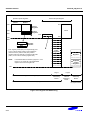
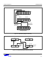
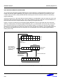
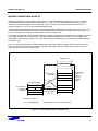
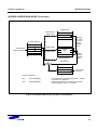
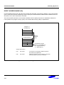
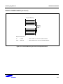
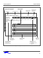
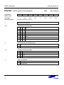
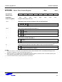
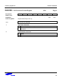
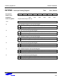
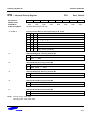
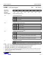
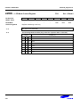
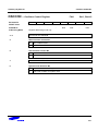
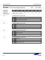
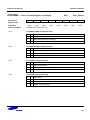
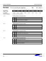
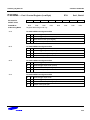
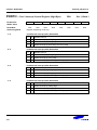
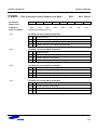
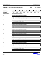
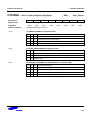
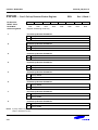
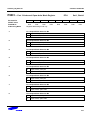
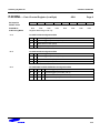
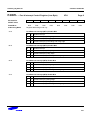
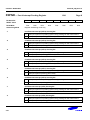
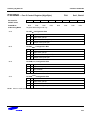
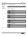
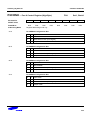
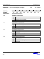
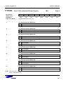
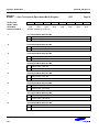
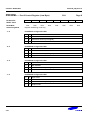
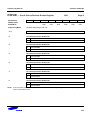
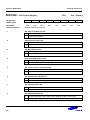
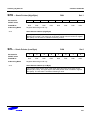
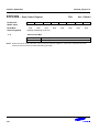
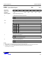
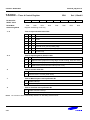
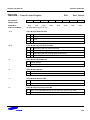
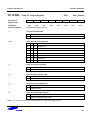
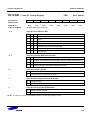
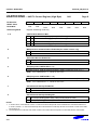
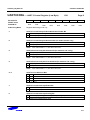
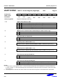
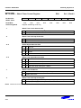
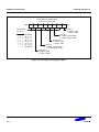
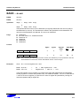
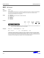
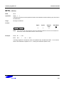
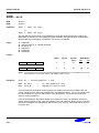
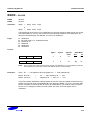
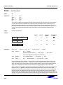
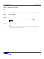
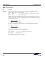
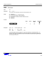
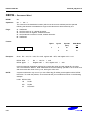
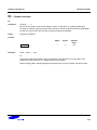
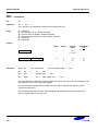
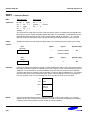
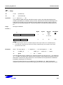
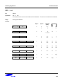
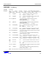
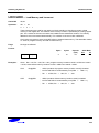
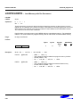
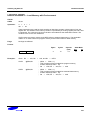
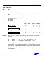
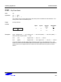
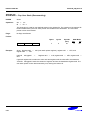
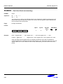
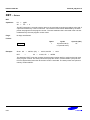
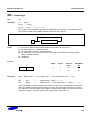
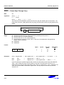
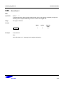
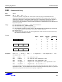
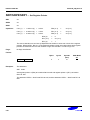
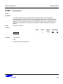
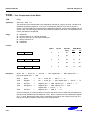
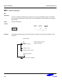
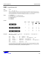
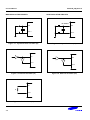
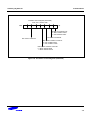
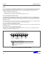
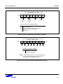
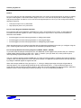
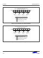
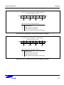
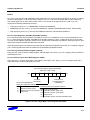
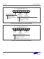
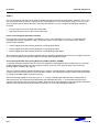
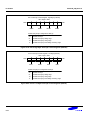
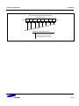
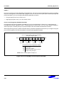
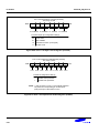
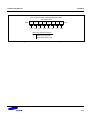
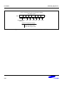
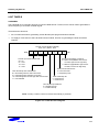
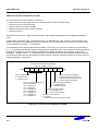
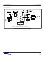
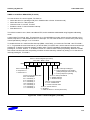
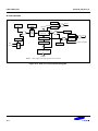
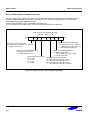
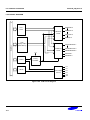
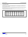
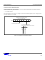
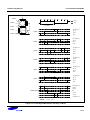
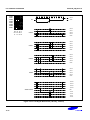
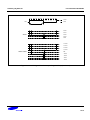
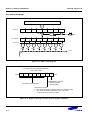
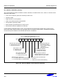
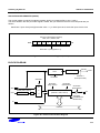
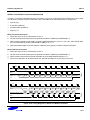
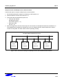
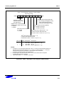
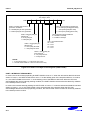
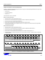
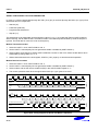
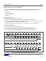
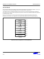
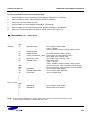
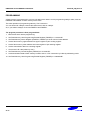
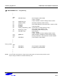
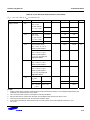
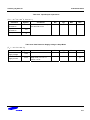
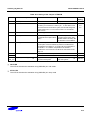
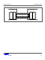
S3F84YB_UM_REV1.00
I/O PORTS
PORT 2
Port 2 is an 8-bit I/O port with individually configurable pins. Port 2 pins are accessed directly by writing or reading
the port 2 data register, P2 at location 02H in page 8. P2.0–P2.7 can serve as inputs (with or without pull-ups),
and push pull outputs. And the P2.7–P2.0 can serve as segment pins for LCD or you can configure the following
alternative functions:
— Low-byte pins (P2.0–P2.3): INT0-INT3
— High-byte pins (P2.4–P2.7): INT4-INT7
Port 2 Control Register (P2CONH, P2CONL)
Port 2 has two 8-bit control registers: P2CONH for P2.4-P2.7 and P2CONL for P2.0-P2.3. A reset clears the
P2CONH and P2CONL registers to "00H", configuring all pins to input mode. In input mode, three different
selections are available:
— Schmitt trigger input with interrupt generation on falling signal edges.
— Schmitt trigger input with interrupt generation on rising signal edges.
— Schmitt trigger input with interrupt generation on falling/rising signal edges.
When programming the port, please remember that any alternative peripheral I/O function you configure using the
port 2 control registers must also be enabled in the associated peripheral module.
Port 2 Interrupt Enable and Pending Registers (P2INTH, P2INTL, P2PND)
To process external interrupts at the port 2 pins, the additional control registers are provided: the port 2 interrupt
enable register P2INTH (high byte, E8H, set 1, bank 1), P2INTL (Low byte, E9H, set1, bank1) and the port 2
interrupt pending register P2PND (EAH, set 1, bank 1).
The port 2 interrupt pending register P2PND lets you check for interrupt pending conditions and clear the pending
condition when the interrupt service routine has been initiated. The application program detects interrupt requests
by polling the P2PND register at regular intervals.
When the interrupt enable bit of any port 2 pin is “1”, a rising or falling signal edge at that pin will generate an
interrupt request. The corresponding P2PND bit is then automatically set to “1” and the IRQ level goes low to
signal the CPU that an interrupt request is waiting. When the CPU acknowledges the interrupt request, application
software must the clear the pending condition by writing a “0” to the corresponding P2PND bit.
9-9