1
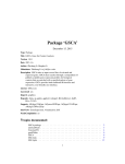
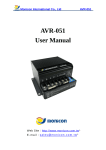
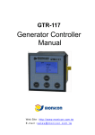
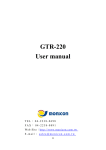
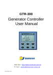
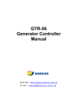
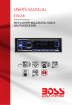
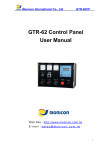
GTR-200
Generator Controller
Manual
Web Site:http://www.monicon.com.tw
E-mail:[email protected]
GTR 200 Generator Controller Manual
1 INTRODUCTION
The GTR-200 is a full digital Gen-set controller equipped with all basic functions and LCD panel that
includes error message display; faulty input detection, analog signal measurement and generator status.
When the error occurred, GTR-200 shuts down the engine and real-time diagnosis can be done easily by
reading LCD panel information. Furthermore, parameters can be adjusted from front panel in accordance
with user’s requirement by six setup keypad. Operating DC power range is from 8 to 38 volts and low power
consumption in standby mode which is suitable for small battery charger.
2 FEATURE
Analog Display includes: Coolant temperature, Oil pressure, Running hour, AC frequency, Engine
speed, DC voltage, 3 phases AC voltage, 3 phases AC current, and 3 phases to neutral AC
voltage.
Protection information includes: Over speed (RPM), Low Frequency, High Frequency, High
Coolant Temperature, Low Oil pressure, Over Crank, Low Fuel Level, Low Coolant Level, Low
Battery, Sensor Open and Short, 24 error recorders, Fail to start recorder, and Total start attempts
recorder.
System Operation Buttons: Off, Auto, Manual, Pre-Heat, Stop, Rated / Idle.
Parameters are Programmable by six setup keypads on the front panel.
Super wide operating DC power range from 8 to 38 volts.
Two colors back light makes it easier to distinct system status.
9 output Power Relays not only provide several functions but also endure heavy power capacity
Equipped with high security terminal connector that provides easy plug-in and removal.
3 Specification
DC power input range
8 ~ 38 VDC
Power consumption
Max. 250 mA @ 12 V; 150 mA @ 24 V
Measured Frequency
Range: 0 ~ 80 Hz
Minimum detecting volts: 10 V (AC)
Accuracy: 99.8%
DC volt meter
Range: 10 ~ 31 V
Accuracy: 99.5%
AC volt meter
Range: 15 ~ 512 V
Accuracy: 99.5%
AC current meter
Range: Convert via CT ratio
File version: MG200V05E
2
GTR 200 Generator Controller Manual
Accuracy: 99.5%
Output capacity
8A / 30 V
Operating temperature
-30 ℃ ~ 70 ℃
Storage temperature
-40 ℃ ~ 100 ℃
Dimensions
216 mm × 144 mm × 89mm
Panel cutout
210 mm × 138 mm
Weight
925 g
4 Panel descriptions
4.1
Front view
Fig. 1
File version: MG200V05E
3
GTR 200 Generator Controller Manual
4.2
Circuit Breaker status indication
4.2.1 Circuit Breaker status LED
This LED light up when terminal 43 and terminal 44 are wire shorted.
Indication of circuit
breaker status
The Circuit Breaker status LED is independent from GTR-200.
4.3
LCD display figures
System Status
LCD Line 1
LCD Line 2
LCD Line 3
Operation Mode
4.4
LCD Icon Explanations
Icon
Explanation
Icon
Explanation
Emergency stop
Auto mode
High coolant temperature
Manual mode
Over speed
Off mode
Low frequency
Unit of AC voltage
Low battery
Unit of AC ampere
Low fuel level
Unit of DC voltage
Low oil pressure
Unit of frequency
Low coolant level
Unit of revolution
System not in auto mode
Running hours
File version: MG200V05E
4
GTR 200 Generator Controller Manual
Over crank
Unit of Celsius
Over frequency
Unit of Fahrenheit
Pre-heat
Unit of pressure
Running
Unit of pressure
Stopped
Gen-set system
Idle Mode
Sensor is open
High Voltage
Sensor is shorted
Low Voltage
Sensor alarm/Error occurred
AC short circuit
Parameter number
AC overload
Save configuration
IN 1 Action
Configuration upper limit
IN 2 Action
Configuration lower limit
Fig. 2
4.5
LCD Information
Battery DC voltage readout
Running hours
Coolant temperature readout
Oil pressure readout
AC frequency readout
RPM readout
Gen-set L1-L2 phase voltage readout
Gen-set L2-L3 phase voltage readout
Gen-set L3-L1 phase voltage readout
Gen-set L1 phase ampere readout
Gen-set L2 phase ampere readout
Gen-set L3 phase ampere readout
Gen-set L1-N phase Voltage readout
Gen-set L2-N phase voltage readout
Gen-set L3-N phase voltage readout
Error records
Failed to start record
Total start attempts record
File version: MG200V05E
5
GTR 200 Generator Controller Manual
4.6
Operating Keypads
Setup Keypads
4.6.1 Setup Keypads
a. Under the CODE entry mode, this keypad represents the fourth-digit.
b. Under the PARAMETER setting mode, this keypad switches to next parameter.
a. Under the CODE entry mode, this keypad represents the third-digit.
b. Under the PARAMETER setting mode, this keypad switches to previous parameter.
a. Under the CODE entry mode, this keypad represents the second-digit.
b. Under the PARAMETER setting mode, this keypad increases the setting value.
a. Under the CODE entry mode, this keypad represents the first-digit.
b. Under the PARAMETER setting mode, this keypad reduces the setting value.
Enter or exit the parameter setting mode
Confirm and save the settings
File version: MG200V05E
6
GTR 200 Generator Controller Manual
4.6.2
Information swapping keypad
These two keypads are used for display gen-set information alternately
LCD line 1 : L1-L2 gen-set voltage
L2-L3 gen-set voltage
L3-L1 gen-set voltage
L1-N gen-set voltage
L2-N gen-set voltage
L3-N gen-set voltage
L1-L2
utility voltage
L2-L3 utility voltage
L3-L1 utility voltage
L1-L2 gen-set voltage
……
LCD line 2: L1 gen-set current L2 gen-set current
RPM
L1 Gen-set current ……
L3 gen-set current
Engine
LCD line 3 : Coolant temperature、Run hours、Oil pressure
Coolant temperature、
Battery voltage、Oil pressure
Coolant temperature、Run hours、Oil pressure
Coolant temperature、Battery voltage、Oil pressure ……
4.7
Enter Code mode
The GTR205 enters the PARAMETER setting mode via the “OFF” mode by following steps.
1. Under the OFF mode, Press the keypad
to enter the CODE mode.
2. a. Press the keypad
under the code of “0000”, the GTR-200 shows the information about the total
start attempt record and failed to start as well as error record.
b. Press the button
mode. (See Figure 6)
under the code display “0528”, the GTR-205 goes into the PARAMETER setting
4.7.1 Total start attempts, Fail to start record & Error record.
Continuous start failed, 5 times.
Total start attempts are 24 times.
Low frequency
=>
(Figure 3)
Press the keypad
(Figure 4)
The 8th error
record.
under code display “0000”, the GTR-200 shows the information of total start
attempts and failed to start as well as error record recorded. As the figure 4, LCD shows start failed are 5
times and total start attempts are 24 times as well as the eighth errors record is
keypad
to see the previous error recorded and press
record.
File version: MG200V05E
7
or
(Low frequency). Press
to see the previous or next error
GTR 200 Generator Controller Manual
4.7.2 CODE mode entry
Code”0528”
Setting value: 10 seconds
=>
=>
(Figure 5)
(Figure 6)
Under the OFF mode, Press the keypad
times and press the keypad
Parameter icon
(Figure 7)
Parameter 1
to enter the CODE mode. Press the keypad
2 times and press the keypad
5
8 times to get the code “0528”. As
shown on figure 6. To enter the PARAMETER setting mode by pressing
under correct code input, the
GTR-200 switches into parameter setting mode and parameters switch alternately by pressing the keypad
or
.
4.7.3 Parameter setting mode
=>
(Figure 8)
=>
(Figure 9)
(Figure 10)
Figure 8 shows the Parameter 1 and the setting is 10 seconds. By pressing
or
to decrese or
increase the setting. For example, To decrese the setting from 10 to 8 seconds by pressing the keypad
twice (As Figure 9) and then press the confirmation button
, the LCD shows “SAVE” on the place of
“PARA” for half second. The “SAVE” shows up that means the parameter setting has been changed
successfully. In the meantime, the LCD screen changes form Figure 9 to Figure 10 for one second and
then back to figure 9 again. To increse the setting value from 10 to 12 seconds by pressing the keypad
twice, and then save the the setting. To discard the parameter setting by pressing the keypad
to return to the previus page or pressing the keypad
or
to go to next or previous parameter.
4.7.4 Parameter setting value range
(Figure 11)
By pressing
Stop duration
or
(Figure 12)
may reach the upper or lower limit of parameter setting. For example : The
ranges from 5 to 40 seconds.
If the LCD shows
File version: MG200V05E
that means the setting has reached to bottom limit and
8
means that the
GTR 200 Generator Controller Manual
setting has reached to upper limit.
5 Operation instruction
5.1
Please refer to Figure 17 for wiring connection.
5.2
When the GTR-200 connects to the DC power, the LCD panel lights up all icons.
5.3
After one second, the GTR-200 is in OFF mode and information page displays
L2-L3 voltage, L2 current and battery voltage.
5.4
Operating keypads
Manual
Auto
Off
Clear
Pre-heat
Idle|Rated
5.4.1 Manual:
Press the keypad
for 2 seconds under the mode of AUTO or OFF to start the engine. Then LCD
shows the icon
representing it is in the state of pre-heat. After pre-heat, engine starts immediately. If
engine failed to start, the GTR-200 returns to the OFF mode. The pre-heat state may not perform, if the
parameter setting of pre-heat is 0 second.
5.4.2 AUTO:
Press the keypad
to switch the GTR-200 into AUTO mode. In the Auto mode, the GTR-200
starts the engine if T18 and T19 are wire shorted and then the LCD shows the icon
, only if pre-heat
state is enabled. After pre-heat is finished, the engine starts to crank. If the engine failed to start, the system
returns to the pre-heat state and then start to crank the engine again. For example, if the conditions and
parameter settings are given as follow. All crank criteria are deactivated and Parameter 1: Stop duration is
10 seconds, Parameter 3: Crank attempts are 3 times as well as the Parameter2: Pre-heat duration is 0
second. In the Auto mode, the engine cranks 10 seconds while detecting T18 and T19 wire shorted, and
then stop for 10 seconds. After 3 attempts of cracking, the LCD shows the over crank icon
and the
alarm is triggered.
5.4.3 OFF:
Press the keypad
File version: MG200V05E
to stop the running engine and then
9
icon shows on the LCD. After 10 seconds
GTR 200 Generator Controller Manual
(depends on Parameter 1), the engine stop completely and icon
the LCD if the idle function is enabled.
disappears. The icon
appears on
5.4.4 Clear:
Press the keypad
to clear error and deactivate alarm. The LCD back light turns red when errors
detecting by GTR-200. Then GTR-200 stops the engine and shows the error messages on the LCD. The
button
clears error and switches the GTR-200 into OFF mode.
5.4.5 Pre-heat:
Press the keypad
to manually activate the pre-heat output under OFF or AUTO mode. If the
generator is running, the pre-heat function is prohibited.
5.4.6 Rated|Idle:
Press the keypad
to switch the engine to rated or idle speed. The icon
displays when the
engine is running at idle speed. Press the keypad
again to switch the engine to rated speed and vice
versa. The idle function performs by a relay which outputs a signal (dry contact) to speed governor controller.
File version: MG200V05E
10
GTR 200 Generator Controller Manual
6 Parameter setting
6.1
Stop duration
Range: 5~40 sec.
Default: 10 sec
Description: Engine stopping time, this affects the duration of the stop output period.
6.2
Pre-heat duration
Range: 0~10 sec.
Default: 0 sec.
Description: The pre-heat duration means the time before the engine starts.
6.3
Crank attempts
Range: 1~9 attempts
Default: 3 attempts
Description: When cranking attempt is equal or greater than this setting, the GTR-200 stops cranking
the engine and display over crank failure.
6.4
Cooling duration
Range: 0~625 sec (Setting value : 0~250, Cooling time=Setting X 2.5sec)
Default:
0 sec
Description: After receiving normal stop command, engine goes into cooling mode and engine runs
until the time of this setting is reached.
6.5
Idle duration
Range: 0~1250 sec (Setting value : 0~250, Idle running time=Setting X 5secs)
Default: 0 sec
Description: After engine starts successfully, engine goes into idle mode if the Idle duration is not zero.
6.6
Low battery
Range: 9~32 V
Default: 20 V
Description: When the battery voltage is lower than this setting, the GTR-205 shows low battery fault.
6.7
High frequency setting
Range: 48~70 Hz
Default: 66 Hz
Description: When frequency is greater than this setting, the GTR-205 shows high frequency fault and
shuts down the engine.
File version: MG200V05E
11
GTR 200 Generator Controller Manual
6.8
Protection function 1
Range: 0~255
Default: 255
Description: Enable or disable protection function 1
Over
EMS
Frequency
L.O.P
H.W.T
32
16
L.W.L
Over
Speed
L.F.L
Low
Frequency
Result
Weight
128
64
8
4
2
1
Ex.
Default
⌦
⌦
⌦
255
Table 1
In table 1“ ” means [Enable], “ ” means [Disable].
The setting can be calculated by adding all related bits multiply its weighted value.
For example: The setting is
128+ 64 + 32+ 16 + 8 + 4 + 2 + 1 = 255
6.9
Low frequency setting
Range: 42~61 Hz
Default: 54 Hz
Description: When AC frequency is lower than this setting, The GTR-200 shows low frequency error
and shuts down the engine, if protection function is enable.
6.10
Input switch type
Range: 0~63
Default: 29
Description: Designate switch type as normal open or normal close.
Reserve
Weighted
Ex.
128
Pressure
build
Reserve
deactivate
Starter
64
32
L.F.L
switch
L.W.L
switch
H.W.T
switch
EMS.
switch
L.O.P.
switch
16
8
4
2
1
Default
⌦
⌦
⌦
6.11
Result
29
Table 2
In table 2, “ ” means input switch as [normal open type] and “ ”means input switch is [normal close
type].
The setting can be calculated by adding all related bits multiply its weighted value.
For example: If the setting of Pressure build deactivates Starter is disabled and EMS switch type is
normal close, the setting is 16+ 8 + 4 + 2 + 1 = 29
Oil pressure switch deactivates starter delay
Range: 0.4~6 sec (Setting value : 2~30, Delay time=Setting X 0.2sec)
Default: 1.2 sec (6 X 0.2 = 1.2)
Description: When oil pressure switch is activated and its active period is longer than this setting, the
GTR-200 deactivates the starter motor, if the Parameter 10 setting value “Pressure build deactivate
Starter” is enabled. This setting has nothing to do with low oil pressure delay. The Low oil pressure
delay is 1 second which is a fixed value and stated on the 7.4 system parameter.
File version: MG200V05E
12
GTR 200 Generator Controller Manual
6.12
Coolant temperature sender brand selection
Range: 0~2
Default: 1
Description: Select the brand for coolant temperature sensor.
(0: SUSUKI, 1: SCD, 2: VDO)
6.13
Oil pressure sender brand selection
Range: 0~3
Default: 1
Description: Select the brand for oil pressure sensor. User selects the brand for oil pressure sensor.
(0: SUSUKI, 1: SCD, 2: VDO 10 BAR, 3: VDO 5 BAR)
6.14
Current Transformer Ratio selection
Range: 50/5~6000/5
Default: 500/5
Description: Selects current transformer ratio.
50/5, 75/5, 100/5, 2: 150/5, 200/5, 250/5, 300/5, 400/5, 500/5, 600/5, 800/5, 1000/5, 1200/5, 1500/5,
1600/5, 2000/5, 2500/5, 3000/5, 3200/5, 4000/5, 5000/5, 6000/5
6.15
Low voltage setting
Range: 186~440
Default: 346
Description: When output AC voltage is lower than this setting, the GTR-200 shows low voltage error
and shuts down the engine if protection function is enabled.
6.16
High voltage setting
Range: 220~484 Volts
Default: 414 Volts
Description: When output AC voltage is higher than this setting, the GTR-200 shows high voltage error
and shuts down the engine if protection function is enabled.
6.17
AC short setting
Range:100~500
Default: 450
Description: When output AC current is higher than this setting, the GTR-200 shows AC short error
and shuts down the engine if protection function is enabled.
6.18
AC overload setting
Range: 40~500 (depends on Parameter 14 )
Default: 400
Description: When output AC current is higher than this setting, the GTR-200 shows AC overload error
and shuts down the engine if protection function is enabled.
File version: MG200V05E
13
GTR 200 Generator Controller Manual
6.19
High water temperature setting
Range: 75~120 ℃
Default: 100
Description: When coolant temperature is higher than this setting, the GTR-200 shows high water
temperature error and triggers the alarm.
6.20
Low oil pressure setting
Range:5~65 Psi
Default:15
Description: When oil pressure is lower than this setting, the GTR-200 shows low oil pressure fault
and triggers the alarm.
6.21
Protection function 2
Range:0~255
Default:143
Description: Enable or disable protection function 2
Shut down
after trip
Not in
Auto.
LOP alarm
HWT
alarm
Over
current
Short
Circuit
Low
voltage
High
voltage
128
64
32
16
8
4
2
1
Weighted
EX.
Default
⌦
⌦
⌦
Result
143
Table 3
In table 3 “ ” means [Enable], “ ” means [Disable].
The setting can be calculated by adding all related bits multiply its weighted value.
For example: 128 + 8 + 4 + 2 + 1 = 143
6.22
Display option
Range:0~31
Default:28
Description: Select an option for display the desired parameter source or unit.
Weighted
Sample
Minimum Minimum
RPMvoltage frequency
PSI/BAR
Real/convert.
detect
detect
Reserve
Reserve
Reserve
Reserve
Reserve
Disable
Disable
Real RPM
PSI
℃
Reserve
Reserve
Reserve
Enable
Enable
Frequency
convert
BAR
℉
128
64
32
16
8
4
2
1
Result
Default
28
Table 4
⌦
⌦
⌦
℃/℉
Reserve
In table 4 “ ” means [Enable], “ ” means [Disable].
The setting can be calculated by adding all related bits multiply its weighted value.
For example: 28 ( Display : Frequency convert to RPM/ PSI/ ℃)
File version: MG200V05E
14
GTR 200 Generator Controller Manual
6.23
The revolution of deactivating starter
Range:150~900
Default:480
Description: When engine speed is higher than this setting, the GTR-200 deactivates starter while
cranking.
6.24
Over speed
Range:980~2100 (RPM)
Default:1980 (RPM)
Description : When engine speed is higher than this setting value, the GTR-200 shows over speed
error and shuts down the engine if protection function is enabled.
6.25
Stop / Trip Option
Range:0~255
Default:0
Description: Select the protection level for each faulty input.
Weighted
Level
Default
Over
Load
AC Short
Low
Voltage
High
Voltage
Low Fuel
Level
IN2
IN1
Low
Frequency
128
64
32
16
8
4
2
1
0
0
0
0
0
0
0
0
Result
0
Table 5
⌦
⌦
In table 5 “ ” means [Trip], “ ” means [Stop].
All protection functions listed above are for shunting down the engine.
6.26
Pre-activate fuel timer
Range:0~30 (Second)
Default:0
Description: This setting designates the fuel output before cranking, if the setting value is not zero.
6.27
Revolution numerator
Range:0~200
Default:10
Description: This Parameter is related to Parameter 28
6.28
R.P.M. denominator
Range:0~200
Default:10
Description: The revolution numerator and denominator are the ratio of engine revolution versus total
number of fly wheel teeth or the RPM of fly wheel versus the RPM of alternator charger.
For example: Set up the revolution numerator and the denominator to 1 to find input pulse from the
LCD.
File version: MG200V05E
15
GTR 200 Generator Controller Manual
(A) If the engine revolution is 1800 and alternator revolution is 460 (input pulse), the numerator could
be set to 90 and denominator could be set to 23.
Solution: 1800 / 460 = 3.913
The R.P.M. calculation formula is as below
R.P.M. = Input pulse * (revolution numerator / revolution denominator)
1800 = 460 * (90/23)
(B) If the engine revolution is 1500 and total count of fly wheel teeth in one second is 4437 (input
pulse), the numerator should be set to 45 and denominator should be set to 133.
Solution: 1500 / 4437 = 0.338
The R.P.M. calculation formula is as below
R.P.M. = Input pulse * (revolution numerator / revolution denominator)
1500 = 4437 * (45/133)
(C) If the teeth count of engine flywheel is 118. Assume the rated rpm of Gen-set is 1500 rpm. Then
the 1500 rpm/50hz => 30 rps/per second also generate 30 x 118 =3540 electronic signals. Then
1500 / 3540 = 0.423 (75/177=0.423), set the numerator to 75 and the denominator to 177.
6.29
Safety on timer
Range:5~40 (Second)
Default:0
Description: All faulty inputs are ignored until safety timer expired. Except the Emergency stop, over
speed, over frequency and low water level.
6.30
Shut down after trip timer has expired
Range: 30~7200 (Second)
Setting Range: 1~240
Setting value: 1
Note: Delay time = Setting x 30 Sec.
Default: 30 (1 x 30 = 30)
Description: When trip occurred, the running icon
is flashing and the designated relay output is
activated. The GTR-205 shuts down the engine if the fault is not cleared before this timer expires.
6.31
Output 0
Relay Output List
Range:0~27
Default: 0 (All errors)
Description: Please see Relay Output List.
6.32
Output 1
Range:0~27
Default:3 (Pre-heat output)
Description: Please See Relay Output List
File version: MG200V05E
16
GTR 200 Generator Controller Manual
6.33
Output 2
0. All errors
Range:0~27
Default:12 (System in Auto Mode)
Description : Please See Relay Output List
6.34
1. System Trip
2. Genset Power Ready
Trigger
Output 3
3. Pre-heat Output
Range:0~27
Default:1 (System trip)
Description : Please see Relay Output List
4. Pre-activated fuel
5. Idle Output
6. Over Speed (RPM)
6.35
Output 4
7. Over Frequency
Range:0~27
Default:2 (Genset power ready trigger)
Description : Please see Relay Output List
6.36
8. Low Frequency
9. Low Oil Pressure
10. High Water Temperature
Relay 5 (GTR-205 only)
11. System not in Auto Mode
12. System in Auto Mode
Range:0~27
Default:27 (Genset in Normal)
Description : Please see Relay Output List
6.37
13. Genset Running by Manual
operation
14. Over Crank
User code 1
15. Over AC Voltage
Range:01~99
Default:28
Description: Change the user code 1 (0528).
Note: By pressing
6.38
&
16. Under AC Voltage
17. AC Over Current
to save the changed value.
19. Low Battery
User code 2
20. Auxiliary Input 1
Range:00~99
Default:05
Description: Change the user code 2 (0528).
Note: By pressing
&
18. AC Short Circuit
21. Auxiliary Input 2
22. Low Fuel Level
to save the changed value.
23. Low Water Level
24. Emergency Stop
25. Sensors Alarm
26. Genset Power Ready
27. Geneset in Normal
List 5
File version: MG200V05E
17
GTR 200 Generator Controller Manual
7 System parameters
Emergency stop delay:
0.4 sec/ action: stop
Over frequency delay:
2 sec/ action: stop
High coolant temperature delay:
1 sec/ action: stop
Low oil pressure delay:
1 sec / action: stop
Low coolant level delay:
4 sec/ action: stop
Low frequency delay:
6 sec/ action: trip or stop (see 6.25 parameter 25 )
Low fuel level delay:
4 sec/ action: trip or stop (see 6.25 parameter 25 )
Input 1 / Input 2 delay
2 sec/ action: trip or stop (see 6.25 parameter 25 )
Over load delay
15 sec/ action: trip or stop (see 6.25 parameter 25 )
AC short delay
0.5 sec/ action: trip or stop (see 6.25 parameter 25 )
Low voltage delay
2.5 sec/ action: trip or stop (see 6.25 parameter 25 )
High voltage delay
2.5 sec/ action: trip or stop (see 6.25 parameter 25 )
Low Battery Voltage:
5 sec/ action: alarm
Circuit breaker closed delay:
7.5 sec
(After Gen-set normally runs about 7.5second, the terminal T41 and terminal T42 forms a dry
contact output circuit for about 1 second.)
Frequency release motor:
16 Hz
Cranking time:
10 sec
Protection pending time:
10 sec
(After Gen-set starts successfully for about 10 seconds, in this time period the controller bypasses
the faulty signal, except the emergency stop and the over speed.)
File version: MG200V05E
18
GTR 200 Generator Controller Manual
8 Back view Description
8.1
Back view
Fig. 13
8.2
Pin definition
Pin
1
2
3
4
5
6
7
8
12
13
14
15
16
17
18
19
23
24
25
26
27
Description
Positive
negative
Starter output
Fuel valve output
Stop output
Alarm output
Aux. output 0
Aux. output 1
Aux. input 2
Low coolant level switch input
Emergency stop switch input
Low fuel level switch input
Low oil pressure switch input
High coolant temperature switch input
ATS remote control input contact Pin1
ATS remote control input contact Pin2
Frequency input contact Pin1
Frequency input contact Pin2
Not connected
Coolant sensor input
Oil pressure sensor input
Pin
28
29
30
41
42
43
44
45
46
47
48
51
52
53
54
55
56
57
58
59
60
Table 6
File version: MG200V05E
19
Description
Speed input contact Pin1
Speed input contact Pin2
Aux. input 1
Aux. output 4
Aux. output 4
Gen-set on load Indication input
Gen-set on load Indication input
Aux. output 2
Aux. output 3 (Normal Open)
Aux. output 3 (Common Pin)
Aux. output 3 (Normal Close)
L3 Phase Current Input (L)
L3 Phase Current Input (K)
L2 Phase Current Input (L)
L2 Phase Current Input (K)
L1 Phase Current Input (L)
L1 Phase Current Input (K)
N Phase Power Input
L3 Phase Power Input
L2 Phase Power Input
L1 Phase Power Input
GTR 200 Generator Controller Manual
8.3
V.R. Function
V.R. is adjustment for matching tolerance between external and internal measuring meter readout. All
values can be shown on LCD panel.
8.3.1 VR1:AC Voltage adjust - fine tuning
8.3.2 VR2:AC Current adjust - fine tuning
8.3.3 VR3:Water temperature value - fine tuning
8.3.4 VR4:Oil pressure value - fine tuning
File version: MG200V05E
20
GTR 200 Generator Controller Manual
9 Dimensions
Fig. 14 Back view
Fig. 15 Side view
Fig. 16 Top view
File version: MG200V05E
21
GTR 200 Generator Controller Manual
10 Wiring Example
+
A
F
S
Aux. Sta rter
F ule R elay
Alar m
S top Re la y
Water L eve l S W.
E mergen cy S top
F uel Level S W.
O il Pr essure SW.
Water Temp. SW.
~
5 ~290 ACV
Water Temp. Sensor
Oil Pressure Sensor
* Please make sure to connect all 6 wires to the CT input pins
* Generator-N wire must be connected to the controller
GTR-200 Controller
30. Aux. Input 1
29. Speed
29. Speed
27. O.P.Sen.
26. W.T.Sen.
25. Spare
24. Freq.D.2
23. Freq.D.1
19.
18.
17. H.W.T Input
16. L.O.P Input
15. L.F.L Input
14. E.M.S Input
13. L.W.L Input
12. Aux. Input 2
8. Output 1
7. Output 0
6. Stop
5. Alarm
Fu se
L1
L2
G EN ER ATOR
C T1
CT 2
LOAD
L3
N
EG
For Contactor
indicator
N FB
No Fuse
Breaker
C T3
MC
Magnetic
Contector
EG
EG
GTR-200 Controller
60. Generator-L1
59. Generator-L2
58. Generator-L3
57. *Generator-N
56. *L1 Amp. (K)
55. *L1 Amp. (L)
54. *L2 Amp. (K)
53. *L2 Amp. (L)
52. *L3 Amp. (K)
51. *L3 Amp. (L)
48. Output 3 (N.C.)
46. Output 3 (N.O.)
47. Output 3 (Com.)
45. Output 2
44. C.B.Indicate
43. C.B. Indicate
42. C.B.Close
41. C.B.Close
22
File version: MG200V05E
4. Valve
3. Motor
2. Battery1. Battery+
Batt ery
8 ~ 36V
The controller is designed for Star connection.
Fig.17