1
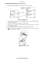
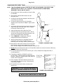
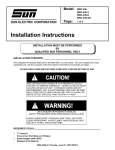
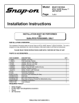
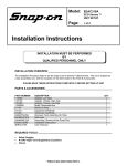
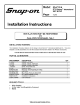
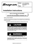
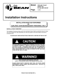
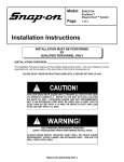
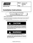
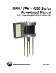
Model:
SNAP-ON KOOL KARE
EEAC304C
R-134a UNIT SETUP
Page:
1 of 5
Installation Instructions
INSTALLATION MUST BE PERFORMED
BY
QUALIFIED SUN PERSONNEL ONLY
INSTALLATION OVERVIEW: _____________________________________________
The Installation Procedures listed are for the SNAP-ON KOOL KARE unit. The unit is shipped as a fully
assembled unit, with the exception of the items listed in the Parts & Accessories List.
PLEASE READ THESE INSTRUCTIONS COMPLETELY BEFORE SETTING UP UNIT
!
THIS UNIT MUST BE PLUGGED INTO A PROPER AC OUTLET FOR UNIT
TO OPERATE CORRECTLY. REFER TO THE UNIT ID PLATE LOCATED
ON BACK OF UNIT. EXTENSION CORDS ARE NOT RECOMMENDED,
BUT IF AN EXTENSION CORD MUST BE USED, USE A CORD THAT IS
LESS THAN 50 FEET WITH A 16 AWG, OR ABOVE 50 FEET AND LESS
THAN 100 FEET WITH A 14 AWG.
!
USE STANDARD REFRIGERANT HANDLING
SAFETY PROCEDURES WHEN PERFORMING INSTALLATION
ALWAYS WEAR SAFETY GOGGLES, DON’T SPILL OR TOUCH LIQUID
REFRIGERANT, AVOID FLAMES, AND EXCESSIVE HEAT. USE ONLY IN
WELL VENTILATED AREA.
TEEAC304C (02/02/1999) REV A.
Page 2 of 5
PARTS & ACCESSORIES: _______________________________________________
PART NUMBER
EAH0001C02A
EAH0001C01A
TEEAC304C
EAK0027C00AS
SS1386VHS
ZEEAC304C
1585
16826
115080
07180108
0647028707
0647028708
0692191401
0692192801
0692224201
4211000101
0692229101
7009244701
DESCRIPTION
Hose, 96” R-134a Blue
Hose, 96” R-134a Red
Installation Instructions
Kit, Vehicle Adapter O-Ring
Video Tape
Users Manual
Bottle, Oil Charge
Screw, 8-32x3
Adapter, Low Side Tank (For Virgin Tank to Low Side Adapter)
Holders, Hose (P-Clips)
Adapter, Vehicle, High Side (Coupler)
Adapter, Vehicle, Low Side (Coupler)
MAC’s Form, Mail-In
Product Registration Form
MAC’s Certification Form
Envelope
Product & Warranty Registration
Recovery Tank Assembly
QTY
1
1
1
1
1
1
1
1
1
2
1
1
1
1
1
1
1
1
REQUIRED TOOLS: ____________________________________________________
•
•
•
Screwdriver (Flat Blade and Phillips)
Safety Goggles (0001-5005)
Refrigerant Oil (Mineral) or Superlube (0681-0193-02 or -03)
UNPACKING UNIT AND ACCESSORIES: ___________________________________
1. Cut Straps (A), and slide the carton (B) off the pallet (C).
A
2. Remove the top of the carton (D), and packing foam (E)
from unit. Split the corners of the base carton (F).
D
3. Remove all boxes (G) and packing material (H) from
scale/tank compartment.
E
G
4. Lean the unit (I) so it can be rolled off the base carton (F).
B
H
5. Lean one side of unit (I) so packing foam (J) can be
removed. Repeat for other side.
PL
AC
ED
OV
ER
SC
AL
E
6. Inventory all items (G) using the Parts & Accessories list
and inspect for damage.
7. Discard scale guard (H).
I
J
F
C
FIGURE 1 UNIT PACKAGE
TEEAC304C (02/02/1999) REV A.
Page 3 of 5
PARTS & ACCESSORIES SETUP:_________________________________________
1. Remove the Blue and Red Hoses from the accessories box and OIL the seals on each end.
2. Connect the open end of the Blue and Red Hoses to the low and high side service ports
respectively on the backside of unit.
3. Connect the Red and Blue adapters (0647028707 and 0647028708) to the Red and Blue Hoses
from the service ports respectively.
4. Remove the two P-Clip Hose Holders (07180108) and Screw (16826) from the accessories box.
Slide the red and blue hoses through the p-clips. Using the supplied screw, mount both p-clips to
the unit's back panel near the cord wrap.
5. Place the O-Ring Kit (EAK0027C00AS) on top of unit.
6. Remove the Oil Charge Bottle (1585) from the accessories box. Attach the oil charge bottle to
the port just below the power switch on front of unit. (Refer to the User’s Manual on operation of
the Oil Charge feature.)
7. Peel the backing from the User's Manual Envelope (4211000101) and apply the envelope, with
the open end on top, to either side of the unit, or in the location designated by the customer.
8. Remove the User's Manual, and place the remainder of the documents in the envelope.
BE SURE TO REVIEW THE USER'S MANUAL WITH THE CUSTOMER DURING TRAINING.
9. Place the User's Manual in the Envelope.
10. Remove Recovery Tank (7009244701) from its box. Remove cardboard wrap from Recovery
Tank. Set on floor in front of unit.
PREPARING NEW RECOVERY TANK: _____________________________________
1. Referring to FIGURE 2, open the BLUE valve on
Recovery Tank to release ALL COMPRESSED AIR.
2. Remove the Particle Filter from the Recovery Tank.
OIL seal. (BLUE VALVE)
3. Attach Low Side Tank Adapter (115080) to the BLUE
valve of Recovery Tank. (DO NOT OVER TIGHTEN).
4. Connect the BLUE service hose to the low side tank
adapter. Open the vehicle adapter.
5. Plug AC Cord to a 115VAC outlet. Turn unit on using
the front power switch.
FIGURE 2 RECOVERY TANK
!
THIS UNIT MUST BE PLUGGED IN TO A PROPER AC OUTLET FOR
UNIT TO OPERATE CORRECTLY. REFER TO UNIT ID PLATE LOCATED
ON BACK OF UNIT. EXTENSION CORDS ARE NOT RECOMMENDED,
BUT IF AN EXTENSION CORD MUST BE USED, USE A CORD THAT IS
LESS THAN 50 FEET WITH A 16 AWG, OR ABOVE 50 FEET AND LESS
THAN 100 FEET WITH A 14 AWG.
TEEAC304C (02/02/1999) REV A.
Page 4 of 5
PREPARING NEW RECOVERY TANK continued:
6. Following the displays in FIGURE 3, to program a 10-minute vacuum time.
STARTING
SCREEN
Enter time to pull
Vacuum on vehicle:
10 minutes
UP
DOWN
Enter time to hold
Vacuum:
00 minutes
UP
DOWN
YES
ENTER
Will you Recycle
from Vehicle this
sequence?
YES
Will you be pulling
a Vacuum this
sequence?
YES
NO
NO
Will you be charging
this sequence?
ENTER
YES
NO
FIGURE 3 VACUUM MODE
7. Once completed, close Recovery Tank valve (BLUE) and remove Service Hose from Recovery
Tank. Remove tank adapter.
8. Replace the Particle Filter to the Recovery Tank. (BLUE SIDE)
9. Place Recovery Tank on scale. Tank fittings should face straight out the back of unit. Connect
velcro strap and tighten belt.
10. Remove bubble wrap from Red and Blue Hoses on unit near the recovery tank.
11. OIL seals on the anti-blow back valves on Red and Blue Hoses from unit. Connect respectively
to Recovery Tank. Refer to FIGURE 4
FIGURE 4 INSTALLING TANK
TEEAC304C (02/02/1999) REV A.
Page 5 of 5
CHARGING RECOVERY TANK:___________________________________________
NOTE: THIS PROCEDURE IS USED TO SETUP THE UNIT FOR CHARGING. RECOVERY TANK
SHOULD HAVE AT LEAST A 25” VACUUM. THIS PROCEDURE IS DONE WHEN
RECOVERY TANK IS ON THE SCALE
1. Be sure Recovery Tank valves (B) are closed. Refer
to FIGURE 5
2. Disconnect the Red and Blue hoses from the
Recovery Tank.
3. Connect the low side tank adapter to the Red Valve
on the Recovery Tank (B).
4. Connect the blue service hose (C) (w/vehicle
adapter) to the low side tank adapter. Open vehicle
adapter.
A
5. Connect the other end of the blue service hose to the
Virgin Tank (A). Raise the Virgin Tank to a higher
level than the Recovery Tank.
C
6. Open the Red Valve on the Recovery Tank.
7. Invert the Virgin Tank (A) and open valve. Gravity
and vacuum will transfer the liquid refrigerant to the
Recovery Tank faster than reclaiming it.
8. Press <AMOUNT> to display the amount of
refrigerant that has been transferred.
B
9. After the desired amount of refrigerant has been
transferred, close valves on Virgin Tank and
Recovery Tank. Set Virgin Tank on ground upright.
FIGURE 5 CHARGING TANK
10. Disconnect the blue service hose from recovery tank.
Disconnect the low side tank adapter from recovery
tank. Connect adapter to low side service port on back of unit.
11. Re-Oil seals on anti-blow back valves on Red and Blue Hoses from unit and connect to Recovery
Tank. Open Recovery Tank valves.
12. Connect the blue service hose to the service port. (This is a backward configuration than a
normal operation.)
13. Following the displays in FIGURE 6, perform a
recover mode. This will reclaim the refrigerant from
the hose. (Optional: Opening Virgin Tank valve will
reclaim rest of refrigerant.)
STARTING
SCREEN
Will you Recycle
from Vehicle this
sequence?
YES
14. Once complete, disconnect the blue service hose
from Virgin Tank and service port. Disconnect the
low side tank adapter.
Will you be pulling
a Vacuum this
sequence?
YES
15. Re-install the blue service hose correctly to the
service port.
Will you be charging
this sequence?
REMEMBER TO OIL O-RINGS AND SEALS
WHEN ATTACHING HOSES OR FITTINGS
YES
FIGURE 6 RECOVER MODE
INSTALLATION COMPLETE/SETUP COMPLETE
TEEAC304C (02/02/1999) REV A.
NO
NO
NO