1
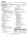
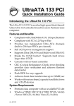
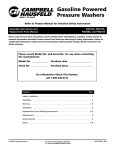
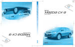
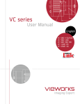
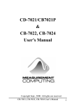
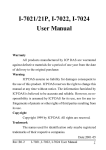
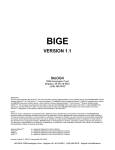
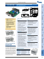
stepping motor connector Motorized Positioners 67 60 3.5 power in Stepper Motor Controller Card with USB Interface 77 70 41 980-0030F-USB stepping motor connector 67 60 3.5 connector P1 power in USB in Optical Tables USB in Ø3.5 connector P1 Ø3.5 41 26 4holes stepping motor 980-0030F-USB driver –Power supply voltage ranges from 12V to 36V – Overcurrent, overvoltage and temperature protection USB out Ordering of 980-0030F-USB series circuit card assemblies (CCA) For added flexibility Eksma Optics offers the 980-0030F-USB series controller in CCA form for ease of integration into custom systems. When ordering the CCA version of the controller the current limit values will still be set by the manufacturer before leaving the factory, but this limit can be changed by the user in the field. The CCA product will also include the USB hub IC and a heatsink for the motor driver IC. Warranty and support options may vary for the CCA version of controller. USB out –Programmable speed and trip points –Programmable acceleration and deceleration ramps – Soft start/stop mode Control –PC control via USB interface – Encoder Inputs for stall detection (shared with Synchronization Input) – Optional handheld remote offers manual two button directional control –Revolutions counter input (shared with Synchronization Input) – Additional features include two programmable limit switches, an emergency limit switch, encoder, and revolution sensor for stall detection and input/output for synchronization – Each 980-0030F-USB controller card comes with an integrated USB hub to allow easy system expansion of additional single- or multi-axis controller cards – Additional controllers can be connected directly to the computer in use or via any other controller card in the system. In either case the software will appropriately recognize the added controller card(s) and treat all connected controllers as a system –Two USB expansion ports can be found on each controller card. Note when ordering encased cards that only the single-axis controller has access to the USB expansion outputs on the rear panel of the unit Programming – Graphical user interface SMCView for Windows 2000/XP/Vista/7 –Drivers and dynamic link library for Windows 2000/XP/Vista/7/Mobile host programming – Set of virtual instruments for National Instruments LabView Mechanical – Operating temperature range: 0 to 70°C –Box size for 1-axis controller : 90 x 120 x 70 mm –Box size for 2 and more axis controller : 180 x 120 x 90 mm Ordering information Code Price, EUR 980-0030F-USB Controller Board 295 980-0131F-USB 1 axis Controller in a box 320 980-0232F-USB 2 axes Controller in a box 550 980-0233F-USB 3 axes Controller in a box 780 980-0234F-USB 4 axes Controller in a box 1010 USB Cable Cable to a Computer – 8CA9(F) - 15(M) actuator - standard length is 1.5 m, other lengths are available by request. Visit www.eksmaoptics.com for new products and prices Motorized Positioners 980-0234F-USB – Speed: 2-5000 steps/s – Synchronization Input and Output USB Expansion 980-0233F-USB –Resolution: full step, 1/2, 1/4, 1/8 Optical Mounts –Targeted for bipolar, two phase stepper motors with current ratings motor limit of 0.25A to 1.5 A.stepping The current driver value is set by the manufacturer Motion Optical Positioners 4holes Base Positioners Electrical 26 Ø3.5 26 ●PWM chopper type current control (up to 1.5 A per phase) ● Resolution: full step, 1/2, 1/4, 1/8 ● Speed: up to 5000 steps/s ●Full featured control software with graphical user interface for Windows 2000/XP/Vista/7 included ● Set of virtual instruments for NI LabView included ●RoHS compliant Specifications Translation & Rotation Stages 77 70 USB out connector P1 Brackets & Rails stepping motor 67 driver 60 Base Mounts & Accessories 77 70 stepping motor connector Adjustment Screws 3.5 USB in 41 4holes 980-0131F-USB 8.180 Opto-MECHANICAL COMPONENTS Manual control of 980-0030F-USB Optical Tables The 980-0131F-USB-MC offers a handheld manual control option that allows for two button directional control of the unit in addition to the USB communication, the buttons are labeled “Forward” and “Backward”. The “Forward” button is intended for moving the positioner “Forward”. The “Backward” button is intended for moving the positioner “Backward”. Two LED’s indicate direction of movement. The LED of interest will flash to indicate rapid movement and will remain constantly illuminated upon reaching the limit switch. The handheld remote is usually used for precise manual positioning of the stage during such processes as calibration. Another common application of is for the control of stepper motors when a computer is not easily accessible. Front panel manual control is available as an option for the 980-0232F-USD-2MC. There are four buttons on this front panel: “Forward Axis1”, “Backward Axis1”, “Forward Axis2” and “Backward Axis2”. There are also four LED indicators to show the direction of movement along with limit switch indication. Brackets & Rails 980-0131F-USB-MC Base Mounts & Accessories Code Optical Mounts 980-0232F-USB-2MC Description Price, EUR 980-0131F-USB-MC 1 axis controller with external wired remote control 390 980-0232F-USB-2MC 2 axis controller with knobs for manual control on box front panel 650 Software Options for 980-0030F-USB controller Optical Positioners The 980-0030F-USB comes with a suite of advanced software tools that can be used to control and adjust stepping motors. All software tools operate on Windows 2000/XP/Vista/7. SMCVieW is a friendly graphical user interface for controlling, monitoring and adjustment of your stepping motors. It can also be used for easy setup and save/load of all parameters for each stepping motor. Interface supports up to 30 drivers simultaneously. USMCDLL.dll is a dynamic link library for host programming in C/C++, Visual Basic and other languages. It includes all basic commands for stepping motors control. Some examples of using these functions are also enclosed. SMC.llb is a set of virtual instruments (VI) for National Instruments LabVIEW 7 programming language. Some examples of using these VI’s are also enclosed. Base Positioners ● 980-0030F-USB is a modified version of previous controller board 980-0030-USB with replaced motor connector from DB15(M) to DB15(F). Translation & Rotation Stages Adjustment Screws SMCView main screen example. Three 980-0030F-USB drives found. Power Supply Motorized Positioners PUP120-17-B1 8.181 A 12V – 36V, 1.5A – 3.6 A power supply is required to operate the controller. You can use your own power supply or the following power supplies: model PSA18U-120 (12 V; 1.5 A) model PSC30U-120 (12 V; 2.5 A) model PUP120-17-B1 (36 V; 3.34 A) See page 8.186 model GS60A24-P1 (24 V; 2.5 A). EKSMA OPTICS • Tel.: +370 5 272 99 00 • Fax: +370 5 272 92 99 • [email protected] • www.eksmaoptics.com Motorized Positioners – USMCDLL.dll is a dynamic link library for host programming in C/C++, Visual Basic and other languages. It includes all basic commands for stepping motor control. Some examples of these functions are also enclosed. – 2D Motion - allows driving two 980-0030F-USB controllers connected in schematic “XY translator”. Included in SMCview inside “Extras” menu, may require separate license. – ENGRAVING add-on - allows driving three 980-0030F-USB controllers connected in schematic “XYZ translator + laser beam shutter”. Included in SMCview inside “Extras” menu, may require separate license. – 3D Motion - allows driving three 980-0030F-USB controllers connected in schematic “XYZ translator”. Included in SMCview inside “Extras” menu, may require separate license. – ATTENUATOR program – this separate program allows driving Motorized Variable Wheel Attenuator (991-0602, 991-0702). May require separate license. Brackets & Rails – Cyclic Motion program - allows motion “from limit switch to limit switch” or “from point to point”. Included in SMCview inside “Extras” menu. Base Mounts & Accessories Users can connect 980-0030F-USB various stepper motors using “bipolar, two phase” connection. We offer many motorized stages that can be driven by 980-0030F-USB: actuators, rotators, translators, variable wheel attenuators. These stages also can be mechanically fixed to various systems: XYZ translators, translators + rotator and others. There are several possibilities to initiate movement actions for mentioned stages connected to 980-0030F-USB: by manual push buttons or by software. Using of software allows automated motion actions required for various scientific experiments or for industrial complex multidimensional movement shape execution. The 980-0030F-USB comes with a suite of advanced software tools that can be utilized to control and adjust your stepping motors. All software tools operate on Windows 2000/XP/Vista/7: Optical Tables Applications of 980-0030F-USB – SMC.llb is a set of virtual instruments (VI) for National Instruments LabView programming language. Some examples of these VI’s are also included. – SMCVieW is a friendly graphical user interface for control, monitoring and tuning your stepping motors. It can also be used for easy setup and save/load of all parameters for each stepping motor. Interface supports up to 30 drivers simultaneously. ATTENUATOR program main screen example Optical Positioners Optical Mounts – USMCDLL.dll for Microsoft Windows Mobile 5.0 (which have just the same functionality as USMCDLL.dll for Microsoft Windows XP). Warning: If a single power supply mode is used, make sure that input voltage is not exceeding 12 V. Otherwise the overheating of the Voltage regulator may happen. Heating the Voltage regulator over 85 °C is forbidden! Warning: Make sure that there are no contact between stepping motor phase windings and 980-0030F-USB ground. Power driver will be damaged obligatory if such grounding present. Warning: You must never connect to, or disconnect from the 980-0030F-USB any stepping motors while the controller keeps currents in the motor windings. Power driver can be damaged if such reconnection happened. Motorized Positioners Warning: Current sense resistors must be chosen for every stepper motor according to its rated current and connection diagram. For more details see 4.2.1. of User Manual. Wrong current sense resistors can cause the malfunction of 980-0030F-USB or damage stepper motor. Warning: 980-0030F-USB power supply must never exceed 36 V. Power driver can be damaged if such exceeding happened. Translation & Rotation Stages Warning: There are appreciable power dissipation on Power driver (up to 6 W depending on input voltage and rated current of stepper motor). Appropriate heatsink must be used to maintain temperature range. Heating the Power driver over 85 °C is forbidden! Warning: There is some power dissipation on Voltage regulator (up to 0.5 W depending on input voltage). Appropriate heatsink may be required. Heating the Voltage regulator over 85 °C is forbidden! Adjustment Screws Warning: The Power driver IC fin (rear) is electrically connected to the rear of the chip. When current flows to the fin, the Power driver IC malfunctions. If there is any possibility of a voltage being generated between the ground of the 980-0030F-USB and the fin, either ground the fin or insulate it. Base Positioners IMPORTANT INFORMATION Visit www.eksmaoptics.com for new products and prices 8.182