1
7715DF
iEEieroFASTIns@!lation Tool
User Manual
\
“ADEMCO
TABLE OF CONTENTS
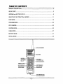
GENERAL DESCRIPTION............................................................................................................. 3
QUICK START ............................................................................................................................<..5
ANTENNAand BA71ERY SETUP ................................................................................................. 9
SELECTING THE OPERATIONALMODES................................................................................ 11
FAST MODE................................................................................................................................. 12
PROGRAM MODE....................................................................................................................... 20
STATUS MODE............................................................................................................................ 22
CUSTOM MODE.........................................................................................................................<23
CABLEMODE.............................................................................................................................. 27
BA~ERY MODE......................................................................................................................... 27
INSTALLMODE........................................................................................................................... 28
II
P
u-ll-
I.,, . .. .. . ..A. ,1..
:e
?,,
!,,
, !,,,,,,,,,,,,
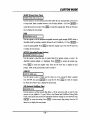
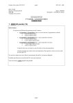
~mt4tWCASLECONNEClMN
MmAvwumow
F+IONECONNECTOR
(FOR
PRL!GFAMMING
NODS)
SAllERY
CHIWGSR
CWNECTOR
TERMINA
SELECTS
REW5
RESETS
ACCEPTS
PROGRAM
!IATAI
MOVES
TONEXlDISPLAY
AClWATSSFAS7
UO05
2
-BA.--AND.
IUSE
ONLYAOEW31
7619
EWIERY)
-2-
GENEMk
DESCRIPTION
(Quick Start Procedures are provided in the next section)
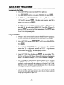
Introduction
The 7715DF MicroFAST Installation Tool is a batte~ powered hand held
Receiver~ransrnitter with a liquid crystal display and an integral keypad for use in
installingalarm radios. Combiningthe receive and transmit functions in a single unit
enables the installer to quickfydeterminethe optimumlocation for the alarm radio by
confirming both the up and down links to nodes, AlarmNet mini-repeatersor node
extender.
The 7715DFincludesan antenna,switchablesignal filter (7715FIL),rechargeablenicad
batterypack, batterycharger,and an interfacecable for prograrrunirrgthe AlarmNet7720
seriesand7820 radios.
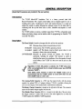
Description
The Power Switch is locatedon the upperleft side, andhas three positions.
OFF Maximumdownposition(towardsbottomof unit).
ON SILENT Centerposition.The 7715DFis operational,but the
(no speaker) speaker is off. This feature conservesbattery power when it is not
necessaryto listento the receivedmessage.
ON W/SPEAKER Maximum up position (towards the display). The 7715DF is
operational, including the speaker. This position is useful in
identifyingthe sourceof an interference.Sincethe speakeris located
on the bottomof the 7715DF it is best not to rest the unit on a flat
surface.
Regardless of which ON position is selected, the 7715DF shuts down
within a pre-programmed time to conserve battery power (see CUSTOM
Submode “SLEEP”).
Some battery power, however, ia used in the “SLEEP” mode, so it is
recommended that the 7715DF’s power be turned OFF when the unit
enters SLEEP mode or is not in use.
The Antenna/Cable Connector is a TNC type that mates directly with the antenna
supplied.An optional TNC to N adapter (Ademco 7715AD) is available,allowingthe
user to test the integrityof the installedradio’scable/antennacombination.
The Battery Charger Connector is locatedon the right side of the unit.This connector
mateswiththe batterychargersuppliedwirhthe unit.
The Modular Phone Comector (RJ4-4),is located on the right side of the unit, above
the charger connector. It mates with one end of the cable supplied for use when the
7715DFemulatesthe ADEMCO7720PProgrammer.
-3-
GENERAL DESCRIPTION
The Alphanumeric Keypad allows access
submodesof the 7715DF,
to
and selectionof all operationalmodesand
The Liquid Crystal Display (LCD)displaysthe followinginformation:
s Operationalmode selected.
. Directionof link (up or downto nodes,mini-repeatersor node extenders)by a blinking
arrowhead.
● Real timereceivedsignalstrength.
● Channelnumber.
● Receivedsignalstrengthon a Oto 10scale.
*Tick marksfor successfullink.
● Cable/antennatest,Good-Bad.
. Variousentryinstructionsas deseribedthroughoutthe manual.
rUPLINK
771 5DF Displav:
-
4
E!!!EEEDOwNL’NK
The operational temperature range
5tYC (122°F), The characteristics
result in a faded display at the low
reduces the visibility of the display
-4-
of the 7715DF is from tYC (32”F) to
of the liquid crystal display (LCD)
end of the temperature range. This
characters.
The following procedures will help you quickly set up and use the 7715DF. For
expandedexplanationson any of theseprocedures,refer to the respectivesectionsfound
later in this manual.
Setting Up the 7715DF
1. Chargethe battery
a. Plug the chargerinto an AC outlet.
b. Conneetthe chargerto the 7715DF.
c. Chargethe batteryfor at least8 hoursbeforeusingthe7715DF,
2. Checkthe batterycondition.
Removethe ~hargerformthe 7715DF.
: Turn the unit on usingthe powerswitchand waitfor it to powerup (about5 sec.),
c. Press ~]
untilthe screendisplaysBATTRY,thenpress ml.
d. The screendisplaysCHECK.Press ~~.
e. A fullychargedbaueryshoulddisplayT99R99.
f. Press ~
twiceto returnto the mainmenuBATTRYdisplay.
3. Enterthe Channelthat willbe used.
a. Press [MODESELECTIuntilthe screendisplaysCUSTOM,then press ml.
b. Pressthe UP amowbuttonuntilthe screendisplaysCH NUM,then press~ml.
c. Enter the channelnumberfor your area (for AlarmNetusers,refer to the Channel
and Odd/’EvenSetting Table on the next page; for Private System users, press
[shift]“E then enterthe channelnumber1-14for the system). Press ml.
4.
Setthe Odd/Evenbit.
a. With CH NUM displayed,press the UP arrow button until the screen displays
O/E, thenpress I-I.
b. Enter 1 for Odd or O for Even (AlarmNetusers refer to the Channel and O/E
SettingTable on the nextpage),thenpress -[.
5. Enterthe CentralStationNumberthat willbe used.
a. With O/E displayed,press the UP aiTowbuttonuntil the screendisplaysCS, then
press 1=1.
b. Enter the 2-digit Central Station ID number, then press 1-1.
For Private System users, refer to the Private System Channel/CentralStation
Table on the next page to determine the central station number based on the
channelin use.
6. Returnto the mainmenuCUSTOMdisplayby pressing~.
-5-
QUICK START PROCEDURES
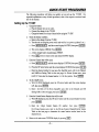
AlarmNet Channel and Odd/Even Setting Table
I CHANNEL
t CHANNEL
I ODDffiVEN I CITY
i CITY
New York
A
Even
Aftanm
F?siladelDhia
A
Odd
Mhneaoolis
Washington
A
Even
Detsoit
Miami
A
IChica,o I
A
Even
I
E, P=2,S=2
Houston
i ODD/BVEN
A
i
Even
A
Even
{
I
A
Even
St.Louis I
A
I
Odd
~ Boston
Odd
: Piwenis
I Maine
I
A
Even
!
D
Odd
Even
Dallas
A
Even
SanFrancisco
A
Odd
Memphis
I E, P=l;, S=10
Los Angeles
B’
Even
Nashville
I E, P=14, S=14 I
Odd
I E, P=2, S=2 ]
Odd
Las Vegas
E, P=3, S=3
Ewn
Tassyta
I
Even
Odd
Private System Channel/Central Station Table
Channel
1
2
3
CS Number
08
10
18
Channel
8
9
10
4
20
11
5
6
7
28
.30
38
12
13
CS Number
40
48
50
58
60
68
70
14
NOTE: Central Station numbers are pre-defined based on the channel in use. Refer to rhis table when
programming the Central Station D number.
Using FAST Mode
Before continuing,make sure the battery is fully charged, and that the correct Channel
Number and Odd/Even setting has been programmed (see Setting Up the 7715DF
previouslydescribed).
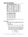
1. Entering Downlink Mode
a.
Turn the unit on and wait for it to powerup (about 5 sec.),then pressthe ~
button.
b. The 7715DF automaticallyentersdownlinkmode. In downlinkmode, the display
shows a tower and a house with an arrow pointing down toward house The
displayindicatesthe towersheardby 7715DFby a dot abovethe numbersor a dot
and a check mark above the numbers.The check mark indicatesthat the signal
strengthis acceptableaccordingto the parametersset in the CUSTOMmode.
L
1 23
4
-6-
S 6789101112131415
QUICK START PROCEDURES
2, Entering the (dowrdink)Mhi-Repeater, NX Extender, or Subscriber Mode
a. Whilein DownlinkMode(step 1),pressthe DOWNarrowbutton.
b. This modeis indicatedby an “R’, “N’, or “S”in the displaywhere:
R = AlarmnetMini-Repeater;N= 7720 NX node extender;S = Subscriber
The next 4 characters,ranging from 0000-9999, represent the 4-digit account
numberof the NX Extender,MiniRepeateror Subscriber.
The last chmacteris the receivedsignalstrengthrangingfromO-A.
The dot over a numberindicatesthe numberof extendersor mini-repeatersheard.
A checkmarkindicatesthe signalstrengthis greaterthan the minimumassigned.
L
1234567891011121
S141S
3. Entering Uplink Mode
a. If in DowrdinkMode,press~
button,thenpress ~
to displayD LINK,otherwise,pressthe ~
to displayD LINK.
b. With D LINK displayed,press the UP arrow until the screen displaysU LINK,
thenpress 1=1.
c. Selectthe type of radiobeingused: 1=7720,2=7820. Press ml.
d. The display will show a tower and a house with an arrow pointingto the tower.
The displayindicatesthe towershearingthe 7715DFtransmissionby a dot above
the numbersand check mark to indicatereceptionat signal strengthgreaterthan
that set in Custommode.
5#
1 i$
L?)l?i%a
4 56
7S 9101112 !31415
4. Entering the (uplink) Mini-Repeater or NX Extender Mode
a. While in UplinkMode(step3b above),pressthe DOWN arrowbutton.
b. This modeis indicatedby an “R or “N’ in the displayfollowingthe asterisk:
R = AlarronetMini-Repeater;N =7720 NX networkextender
The secondcharacterdisplays“M’ or a space:
M = messageheardby 7720NXthat reportsto user’scentralstation
Space= messageheardby 7720NXreportsto a centralstationotherthanuser’s
The thirdcharacterindicatesaccessibilityto the 7720NXby the use~
Y = userhas acces~ N = userdoes not haveaccess
The lastcharacter(followingthe %“ symbol)is the receivedsignalstrength(O-A).
The dot over a numberindicatesthe numberof extendersor mini-repeatersthat heard
the 7715DF signal. A check mark indicatesthe signal strength is greater than the
minimumassigned.
4.
1 2 S 4 5 6 78 9101? 12111415
-7-
Programming the Radio
1. Turnontie 7715DFand connectittothe radio,Powerupthe radio.
2.
Press ~luntil
thescreen displaysPROGRAM,thenpress ml.
3. The7715DF displaysECPRADIO Y/N? Iftheradio isusing ECPmode, press Shift
+UParrow (Y), then press lml.
Iftheradio isusing zone mode,press Shift+
DOWNarrow(N),thenpress 1~1.
4. The7715DF screen nowgoes blank ~doperates sifilwto a7720Pproym tool.
Press Shift+X. Thescreen displaysREBOOTY/N? Press Shift+UParrow (Y),
then press [-J
andwait untilthe Pittwaybanner appears.Press ml
again.
The unit is now in programmingmode.
Using Install Mode
1, Power uptheradio andwait about 6tinutes fortheend oftiepower-up sequence.
The radio’syellowLED will flashaboutonce per secondwhentheradiois ready.
2. Turnonthe 7715DF,thenpress _~untii
thescreen displays~STW.
Press m.
3. The screen displays CUSTOMERID. Enter the 6-digit customerID in XXYYYY
format, where XX = 2-digit central station ID and YYYY = 4-digit subscriber
accountnumber.Press ml.
4.
The screendisplaysCONNECT.
Connectthe 7715DF to the radio, then press ml.
The screen displaysTX=l,
TX=2, etc. and the ~een LED flashes,indicatingthe transmission of the diagnostic
message.7820 transmits60 messages;7720V2/7720PLUStransmits30 messages.
5. After the messageshave been transmitted,the screendisplaysDISCON.Disconnect
the 7715DF from the radio and press any button. The screen displaysWAIT. It
usuallytakes severalminutesbefore the node messageis displayedon the 7715DF.
Make sure you have determineda good downlink location first, so that you can
successfullyreceivethe messageback fromthe network.
6. When the messageis displayed,the screen shows the node that heard the message
with a dot (and check mark if signalstrengthis above that set in Custommode),the
averagesignalstrength,and the repeatcount.
-8-
ANTENNA AND 8A TTERYSETUP
Connecting the Antenna
Removethe antennafromthe box, and screwit clockwiseonto the antennaconnector(do
not overtighten).
First Time Charging of the Battery
1. Checkthat the powerswitchis in the OFFposition(max.downposition).
2, Removethe batterychargerfrom the box, Connectthe plug on the end of the charger
to the chargerconnectoron the 7715DF.
3. Plug the chargerinto a 120V,60Hz,AC outlet,and allowthe batteryto chargefor at
least8 hours.
4. After at least 8 hours, remove the 7715DF from the charger connectorand remove
thechargerfromthe AC outlet.
5. Slidethe 7715DFs powerswitchto the ON NO SPEAKERor ON WITHSPEAKER
position.
Repeatedlypressthe {-1
thenpress the ml
keyuntil“BATTRY”appearson the display,
key. “CHECK”will be displayed.Press ml
againand
the display will indicate the percent charge state of the batte~ (for example:
“T99R99” indicates a battery voltage of 8 or more volts. See “BATTRY”Mode
sectionfor a detaileddescriptionof the “BATTRY”mode).Placethe powerswitchin
the OFF position,
6. For subsequentchargingof the battery,the charge time will depend on the percent
chargeremainingin the battery.This can be monitoredas indicatedin step 5 above.
Since,duringcharging,all of the high currentcircuitsof the 7715DF are shut down,
the 7715DF can be left in the ON NO SPEAKERposition, CHARGE mode; then
pressing any key except ~
Pressing~
will update the battery capacity measurement.
exitsthe chargemode,but not the charging.
Thebatterycannotbe overcharged,evenif the chargeris left connectedto an AC source.
-9-
ANTENNA AND BATZERYSETUP
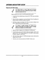
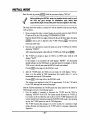
Replacing the Battery Pack
4
,-
The 7715DF’s
battery is a custom “battery pack
and should
not be altered in any way or replaced by any type of battery
other than an Ademco No. 7619.
Makesure that the power switchis in the OFF (maximumdown)position.
1. Loosenthe two bottomknurledscrewsat the rear of the 7715DF,usinga screwdriver
or smallcoin.
2. Removethe batterycompartmentcover fi-omthe bottomof the unit by pullingon its
handle,andremovethe batteryby pullingon its pull-tab.
3. Install the new battery (only AdemcoNo. 7619) in the direction indicated on the
battery.Wrap the batterypull-tabaroundthe battery.
4
If the battery is installed incorrectly, the 7715DF will not
operate, and the battery will not reeeive a charge; no damage
will occur to the battery or the 7715DF, however.
4. Replacethe batterycompartmentcoverand tightenits two holdingscrews.
5. Connectthe plug on the end of the battery charger to the charger connectoron the
right side of the 7715DF. Plug the charger into a 120V,60Hz AC outlet and allow
the batteryto chargefor at least 8 hours.
6. Afterat least8 hours,unplugthe7715DF fromtie chargerconnectorand removethe
chargerfromthe AC outlet.
7. The batterycan be tested as describedin the “BATTRY’Modessection.
-1o-
Slidethe powerswitchto tie desiredON position(e.g.,ON NO SPEAKERor ON WITH
SPEAKER).The windowdisplays“7715DF.”
Aftera fewseconds(assumingno key has been pressed),the displaywill indicate:
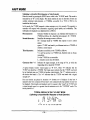
●
SoftwareVersion(VX.X)
●
ChannelNumber(A-E),
where (A-E) indicatesthe primary and secondarychannel pair (see CUSTOM
Mode “CH NUM” sectionfor a listingof the primaryand secondarypairs).The
defaultset at the factoryis “A”or primarychannel2, secondarychannel 10 (the
7715DF generally receives via the primary channel and transmits via the
secondary).
The receive/transmitfinctions of the 7715DFwill be OFF. If any key is pressed,the first
mainoperationalmode “FAST”is displayedon theLCD.
Pressingthe UP arrow and 1-~
keys scrollsthe main operationalmodesin
ascendingorder (1, 2, 3, etc., with vmaparound);pressingthe DOWN arrow key scrolls
themin descendingorder(3,2,1, x etc.).
The mainoperationalmodesare as follows:
FASTMode(FieldAlarmSignalTest)
D LINKdisplaysdownlinkactivitybetween7715DFand network
STATdisplaysstoredstatisticsfromeitherD LINK or U LINK modes
U LINKdisplaysuplinkactivitybetween7715DFand network
● PROGRAMMode
ECP (Y/N)promptselectstype of radioto be programmed
Emulates7720P ProgrammingTool
● STATUSMode
Showsstatusof AlarmNetnodesin your network
● CUSTOMMode
Displaysthe 7715DFprogrammingoptionsone at a time
Allowschangesto 7715DFparameters
● CABLEMode
Checks7715DFantennacableconnection
● BATTERYMode
Checks7715DFbatterycondition
● INSTALLMode
AssistsInstallerin the installationof all one-wayAlarmNetproducts
●
Pressthe ml
key whilethedesiredmodeis beingdisplayedto activatethat mode.
If a selectedmode requires that the receive/transmitfunctionbe on, it is automatically
activatedandautomaticallyshutdownafterterminatingthe mode.
-11-
FAST MODE
Enter this mode from the main menuby eitherpressingthe ml
displays“FAST”or by pressingthe ~
key whilethe LCD
key.“D LINK,”the firstof threesubmodesis
displayed.The threesubmodesareas follows:
D LINK:
Downlinkmode
●Listento anode
● ListentoanAlarmNet
mini-repeater
ornodeextender
STAT:
Downoruplinkstatisticsmode
Uplinkmode
U LINK
Pressthe down or up arrowkeysto scrollto each of thesemodedisplays.Pressm{
to
activatethe displayedmode
Pressthe ~
key to exit anyof thesemodesand returnto the mainmenu.
D LINK (Down Link) Mode
Enter this mode from the FAST menu by pressing ml
“D LINK.” Pressingthe ~
while the display shows
key whilethe main menu is displayedwill also activate
D LINK mode.
D LINK mode can either listen to a node (defaultdisplay),or can listen to an AlarmNet
mini-repeateror node extenderby pressingthe downarrowkey once in D LINKmode.
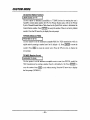
DOWN LINK MODE
Illl!ili
@
7715DF
-
The 771 5DF listens to messages from the nodes (master stations), and identifies the node it
heard from as well as the signal strength and number of messages received. this information
can be reviewed in the “stat” submode.
-12-
Listen to a Node
In this mode,the 7715DF willreceiveon the channelthat was programmedand storedin
the “CUSTOM”mode (defaultchannelset at the factoryis “AJ’that is, 2 on RX, 10 on
TX), and displaysthe following:
Bar Graph:
Indicatesreceivedsignalstrength,updatedevery0.1seconds.Themorebars
displayed,thegeaterthereceivedsignalstrength.
Asterisk
A segmentof theasteriskincrementseachtimea messageis received.(The
messagecountfor eachnode is set to zero uponenteringthe downlink
submode.A countofthenumberof messagesis keptuntilthecountreaches
15.
Pressingthe[-[
keyresetsthecounterto zero.)
House/TowerIcons: Indicatescommunication
from the towerto the installationsite by the
blinkingdownarrow.
NodeNumber:
Node 1-15fromwhichthe messagewas received.The nodenumbers1
through15arealsodisplayedat the bottom.
SignalStrength: Displayedona scaleof 0-10, where10is displayedinhexas “A”.A moving
averageof the receivedsignalstrengthof each node,updatedwith each
messagereceivedis alsokept.AfsoseeCheckMarkdescription.
Checkmerk/Doti As a correctlydecodedmessagefroma node is heard,a dot abovethe
transmitting
nodenumberblinksfora second,andthenturnssteadilyon.A
checkmarkappeamabovea nodenumberif the averagesignalstrengthof
the messagereceivedfromthe nodeis equalto or greaterthanthe vahte
storedin the “CUSTOM”mode“RSSI”option(defaultvalueset at the
factoryis3)and atleastfourmessageshavebeenreceivedfromthatnode
A typicaldisplaywouldappearas “2>5”,where2 is the node numberand 5 is the signal
strengthof the receivedmessage,Referto the followingdiagram.
Thesestatisticscan be viewedin “STAT’modeuponexitingdownlink mode.
NPICAL
DISPLAY IN THE DOWN LINK MODE (Listening to Node)
{.
1 23
4 S6
789101112131415
. Thearrowindicatesthe direction of the link, i.e., Node (master station) to the 7715DF.
. The numeral “2” indicates the node heard by the 7715DF.
. The numeral ‘5’ and the lighted bar graph segments indicate the signal strength heard
.
,
by the
7715DF. The bar graph is updated once every 0,1 seconds.
The aeterisk segments blink in rotation each time the 7715DF receives a message.
The dot above the smell numeral “2’ blinks when the 7715DF hears the node, and stops blinking
one second later. A check appears with the dot if the 7715DF hears at least four messages from
the node wfth an average signal strength equal to or greater than the minimum value programmed.
4
If exceseive interference, such as voices or random
in FAST mode, remove the antenna and connect
signal filter (7715FIL) to the 7715DF. Connect the
switchable signal filter. Set the filter switch to the
listen to a node or the “R-E” position to listen to an
repeater or the node extender.
-13-
noise, is heard
the ewitchable
antenna to the
“N” position to
AlarmNet mini-
Listen to AlarmNet Mh&Repeater or Node Extender
Enter this mode by pressing the DOWN arrow key while in the “D LINK mode. This
mode is indicatedby an “R,”“N,”or “S” in the display as follows.
First characten
Next 4 characters:
Last character:
Indicatesthe type of deviceheardas follows:
R= Alarmnetmini-repeater
N= 7720NXnode extender
S = subscriber
Ranging from 0000-9999, indicates the ID of a subscriber, a
7720NX number, or a 7720NX with a different central station
number.If the four charactersincludea letter,they indicatethe hex
numberidentifyingan AlarmNetmini-repeater.
RangingfromO-A,indicatesthe receivedsignalstrength.
A typicaltext windowwouldappear as “R12A38”,where“R”indicatesAlarmnetmini
repeater,”12A3°the mini-repeaternumber,and “8”the signalstrengthof the received
signaL
The dot over a numberindicatesthe numberof extendersor mini-repeatersheard.A
checkmark indicatesthe signalstrengthis greaterthanthe minimumprogrammedin
“CUSTOM’mode.
TYPICAL DISPLAY IN THE DOWN LINK MODE
(Listening to AlarmNet Mini-Repeater or Node Extender
123
4
5 6
78
The “D LINK” repeater-extender
subscriber’s
installation
9101112131415
mode can be used to check
is functioning
by triggering
that a
an alarm causing
the subscriber
and repeaters
to generate
traffic which will be
displayed
in this mode. It is not recommended
for listening to
7720NXSor Alarmnet mini-repeaters to determine site suitability due
to the unpredictable
nature of traffic from these devices,
-14-
STAT (Down or Up Link Statistics) Mode
Enter this mode from the FAST menu by pressing the m
key while “STAT’ is
displayed. This mode displaysthe statisticsof the informationcollectedin the up and
down linkFASTmodes.This modewill not activateif data is not accumulatedduringthe
up or downlink modes.
Upon entering the “STAT’”mode, the LCD displays the fifteen node numbers at the
bottom.A dot is placedabovea node numberif the node washeardfromduringthe up or
down link mode. The statisticsdisplayedcorrespondto the node indicatedby the blinking
dot. The statistics for the lowest node that was heard from are displayed initially.
Statisticsfor the othernodescan be accessedby repeatedlypressingthe ml
key.
Two numbers are displayed on the LCD (e.g., “15+ 8“). Their meaning depends on
whether“STATmodewas accessedatler the down linkor the up linkmode.
L
E+ flma ‘picALf’sTA~D]sp~y~ERDowNLINKMoDE
STAT mode after Down Link mode:
First numbe~
The number of messages received from the blinking node (e.g. 15+)
Second numbefi
The average signal strength of the last four messages received from the
node. A check mark next to the dot for a received node indicates that node
had an average signal strength equal to or greater than the minimum
programmed value (default =3) (e.g. 8).
STAT mode after Up Link mode
First numbefi
The number of acknowledgments received from the blinking node. If the
number of messages received exceeds 15, the LCD displays 15+.
Second numbefi
The average signal strength at which the nodes received the messages
transmitted by the 7715DF. The signal strength is scaled in order to
account for the difference between the transmitted powers of the 7715DF
and the radio (7720 or 7820) being installed. A check mark appears if the
repeat count is greater man the minimum programmed value (factory-set
default is 30).
The “STAT”modecanbe clearedand newstatisticsaccumulatedby pressingthe ml
key duringthe downlinkor up linkmode.
Subsequently(after the START key has been pressed), if no data is accumulated,the
displaywillindicate“STAT if the “STAT’modeis accessed.
.’
d
If the last mode selected before exiting is the repeater-extender
link mode, no entries will be made in the “STAT” mode,
Pressing the ~
keyexitsthe “STAT mode.
-15-
down
FAST MODE
U LINK (Up Link) Mode
This modeallows the installerto determinehow well the 7715DF is heard by AlarmNet.
WHEN USINGTHIS MODE,HOLDTHE 7715DFNEAR THE BOTTOM(THEEND
OPPOSITE THE ANTENNA),AWAY FROM THE BODY AND IN A VERTICAL
POSITION.
Uplinking to a Node
Enter this mode from the FAST menu by pressing the ml
displays“ULINK”.Exit by pressingthe ~
key while the LCD
key.
Upon entering this mode, “7720/7820(1/2)” is displayed (scrolling).Enter the model
numberof the radio beinginstalled(i.e., 7720 or 7780) by pressing 1 or 2 as appropriate,
then press ENTER. This is necessarysince the 7715DF transmitsat a lowerpower level
than the 7720 and 7820, thus the signal level heard at the node must be scaled by the
7715DFto compensatefor this difference.
In U LINK mode,the 7715DFtransmitsa statusmessageeverytwo seconds(for the time
programmed in “CUSTOM” mode “TRANSMIT TIME option) and listens for a
response from the nodes. Upon receivinga response,the7715DF examinesthe message
to determinethe signalstrengthat whichthe messagewas received.
“UP LINK” MODE
The 7715DF transmits a message to the nodes (master stations). The node or nodes evaluate
the message and each reports back to the 7715DF its node number, and the signal strength and
number of messages it received. This information can be reviewed in the ‘stat’ mode.
The up link displayis similarto thedownlinkdisplay:
Asterisk
Upontransmitting
a message,alleightoutersegmentsoftheasterisklightup
momentarily.
Afterward,a segmentof the asteriskincremen~eachtimea
messageis received.
House/TowerIcorsx Indicates
communication
NodeNumber:
from the tower to the installation
site by the
uparrow.
Node 1-15fromwhichthe messagewas received.The node numbers1
through15arealsodisplayedatthebottom,
blinking
-16-
Displayedon a scaleof0-10,where10is displayedin hexas “A’.A moving
averageof thesignalstrengthat whicheachnodehearsthe7715DFsignal,
updatedwith each messagesent is also kept. Also see Check Mark
description.
CheckMark/Deb As a correctlydecodedmessagefroma node is heard,a dot abovethe
transmitting nodenumberblinksfor a second,and then turnssteadilyon
indicatingadequatesigmdstrength.A checkmarkappearsabovea node
numberif thesignalstrengthreceivedbythenodeis equalto or greaterthan
thevaluestoredin the“CUSTOM”
mode‘TXPASS”option(defaultvalue
setatthefactoryis 3).
Signal Strength:
+
4
:.. .’
.’
The node processes messages in the order they are received thus it
may be necessary to wait several minutes before a response from the
node is sent to the 7715DF.
A typical display would appear as “2>A,” where 2 indicates node 2, and A (hex 10)
indicatesthe strengthat whichthe messagewasreceivedat the node.
TYPICAL DISPLAY IN THE “UP LINK” MODE (Uplinlting to Node)
1 ~3
4 5 6 789101112131415
●
The arrow indicates the direction of the link, i.e., 7715DF to the node (master station).
●
The ‘2” indicates the node (1-15) that heard the 7715DF.
Q The letter ‘A” indicates the signal strength (O-A) heard by the node from the 7715DF.
●
The asterisk btinka each time a message is sent by the 7715DF and blinks a segment in
rotation each time a message is received.
*
The dot above the small numeral ‘Z’ blinks when the 7715DF hears the node and stops
blinking after one second. A check appeara if the signal strength is equal to or greater than
the minimum value (the factory-set default is 3).
●
The letter “m” appears to the right of the asterisk if the acknowledgment for the 7715DF
message was received from a ‘mini”.
The 7715DF stores the number of messagesand a moving average value of the signal
strength at which the message was received. This informationcan be viewed in the
“STAT”modeas describedin the previousSTATMode section.
-17-
FAST MODE
Upliig
to AlarmNet Mini-Repeater or Node Extender
Enterthis modeby pressingthe DOWNarrowwhilein the “ULINK mode.This modeis
indicatedby an “R on the display,This mode enablesthe user to determineif there are
suitable Alarnmet mini-repeaters,or 7720NXS, accessible by a 7720 or 7820 to be
installedat that location.
In this mode, the 7715DF transmitsa status messageeverytwo seconds.The repeateror
extender will respond with informationregarding signal quality and availability.This
informationis displayedas an alphanumericas follows:
First character:
Second characte~
Third characte~
Indicateswhetherthe responseis an Alarnmetmini-repeateror a
7720NXas follows:R = AlarmNetmini-repeateq N= 7720NX
Identifiesthe messagesourceas follows:
M = message heard by 7720NX that reports to user’s central
station
space=77 15DFwas heardby an Alsmnnetminior a 7720NXof
anothera centralstation
Indicatesaccessibilityto the 7720NXas follows:
Y = user has access to a 7720NX (an Alarmnetmini is always
accessible).
N = the 7720NXis not accessible.
L= indicatesaccessmaybe limited.
Character after “>”: Indicatesthe signal strength, in the range of O-A,at which the
respondingdeviceheard the 7715DF.
A typical display window would appear as “N Y>4”, where “N’ indicates that the
7715DF was heard by a 7720NX.The blank space indicatesthat the 7715DF was heard
by an Alarmnetminior a 7720NXof anothercentra[station.The “Y”indicatesaccessto
the device that heard it. The “>4” indicates that the 7715DF was heard with a signal
strengthof 4.
Dots and checks are placed in locations 1-4 (bottom row of display) for the best 4
repeater’sthat were contacted.If less than 4 were contactedonly that numberof dots will
be displayed.Checkmarksare displayedonly for repeater’sthat “heard”the 7715DFwith
a signal strengthequal to or greaterthan the minimumset in the “CUSTOM’mode. The
factorydefaultis 3.
TYPICAL DISPLAY IN THE “UP LINK” MODE
(Uplinking to AlarmNet Mini-Repeater or Node Extender)
A
1 23
4 5 6 78
-18-
9101112131415
#
4
,,. .
To conserve battery power, the 7715DF stays in the up link mode for a
time period as programmed in the “CUSTOM” mode, with a maximum
of 3 min. (default value set at the faotory is 1 min.) The up link mode
can be terminated anytime by pressing the ESC key.
If the STAT submodewas accessed after the U LINK submode,each of the 4 possible
repeater’swill be displayedby a scrollingalpha numeric.The first three are as described
above.The “>”is a separator,withthe followingtwo indicatingthe centralstationnumber
of the repeater.The stoppedscroll with a field of 6 alphanumericcharactersidentifiesa
mini, subscriber,or 7720NX numberin the first 4 charactersrangingfrom “0000-9999”
or 4 “X’”s.Four “x’”sindicates a 7720NX with a differentcentral stationnumber.The
fifth character ranging from “O-A indicates as above, the signal strength that the
respondingdevice heard from the 7715DF. The last characterindicatesthe number of
repeats.
A typicaldisplaywindowwouldappear as “N Y7F1234>A3“. The first three characters
are as explainedabove.The “>” is a separator.“7F identifiesthe centralstation.“1234”
is the subscriber ID. The “A” and “3” are the signal strength and repeat count
respectively.
-19-
PROGRAM MODE
This modeemulatesthe ADEMCO7720P programmingtool andcan be usedto program
the 7720 series and 7820 radios. Enter this mode by scrollingthroughthe main menu of
modesuntilPROGappears,then press 1=1.
The 7715DFdisplaysa maximumof six characters.Further,the 7715DFdoes not display
someof the charactersdkplayed by the 7720P, whichcan display32 characters.Thus it is
necessaryto scroll the long 7720P message on the 7715DF. Charactersthat cannot be
displayedare replacedby spaceswith a maximumof one spacebetweenwords.
Upon entering the PROG mode, the 7715DF queries the installer if the radio being
programmedis to be usedin ECP mode by scrolling“ECP (Y/N).”If the radio is to be
used in ZONE mode, enter “N.” If the radio is to be used in ECP mode, enter “Y,” and
the PROGmodewillbe terminatedupon completionof programmingmode.
No= SHIIT’,thenDOWNarrow,then lml,
Yes = SHIFT,then UP arrow,then ~=1,
in that order,
in that order.
Otherkeys havethe samemeaningas on the 7720P exceptfor:
Escape On 7715DFpress ~.
On 7720P press SHIFT,then ~.
Backspacti On 7715DFpress SHIFT,then BS. On 7720PpressBS.
Start: The STARTkey is not on the 7720P keypad.
Fast: The FAST key is not on the 7720P keypad.On the 7715DF,pressingthe ~
key exits the mode.If themodeis exitedthisway, the installerwillhave to turn the radio
off, then on beforereprogrammingit.
Followinga “Y”or “N”entry, the 7715DF displaywill go blank. From this point on the
7715DF is used as the 7720P. If the radio to be programmedis in ZONE mode and
alreadyrunning,press SHIFT and then X to reboot the radio as wouldbe done with the
7720P. The differencewiththe 7715DF is that whenthe radio reboots,the displayon the
7715DF does not clear like the 7720P. If the radio is alreadyrunningbut is in ECP mode,
power the radio off and then back on. If the radio is off, turn it on. Connectionto the
radio beingprogrammedcan be madeat anytime by insertingthe RJ4-4end of the coiled
cable into the matingRJ4-4 connectorlocated on the right-handside of the 7715DF and
the RJ6-4 end to the radio. Enter programmingmode by pressing ml
while the
LEDs of the radioare flashingand proceed withthe programmingsessionas describedin
the radio’sInstallationInstructions.
-20-
PROGRAM MODE
Whfleprogramming, the installer is prompted to respond to several questions by the
radio, These questions are scrolled on the 7715DF display, In thii and other modes,
messagescan be scrolled again by pressing the SHIFT and then the WI
key,
Followingprogrammingthe radio, the PROG mode is terminatedfor ECP radios. For
non-ECPradios, the 7715DF displays the status message as described below. Pressing
w
at thk
stage
will terminatethe “PROG mode. other functionsof the 7720P cm
also be initiatedusing the 7715DF whilethe statusmessageis being displayed.Pressing
~
while the status messageis being displayed,or before or after programmingthe
radio,terminatesthe programmingmode.
Radio Status Message
Thk message appears tier programmingof the radio is completed. It can also be
displayed by pressing shift-S after the display has gone blank while the 7715DF is
connectedto the programmedradio which is in programmingmode. The status message
normallydisplayed on a 7720P will scroll the followingstring on the 7715DF display
witha pauseof five timesthe scrollrate programmedand storedin the “CUSTOM”mode
(default value set at the factory is 1250 ms) betweeneach. The corresponding7720P
messageis shownbelowit.
7720P DISPLAY:
Z=WWWW(pause) l%a(pause)
1234
TE
WWWWaabbc
llka(pause)
TM
BA DC FLT
BA=b(pause) DC=b(~use)
FLT=c
The characters in the 7720P messages (W, a, b, and c) are modified wheneverthey
assumea formthat cannotbe displayedon the7715DF. W=p (telcorestore)in the 7720P
is replaced by R. b=A(battery charging restored but not reported as restored) is also
replacedby R.
-21-
STATUS MODE
This modedisplaysthe activeAlarmNetnodesin the network.
Enterthis modeby pressing1~1
whilethe mainmenudisplays“STATUS”.
On enteringthe “STATUS”mode,the LCD displays“WAIT”until a message is heard.
I %!kfIm?i?i
I
123456789101112131415
Upon receiving a status message from the network, the LCD displays “DONE” and
indicateswhichof the AlarmNetnodesare activees follows:
Check Mark = indicatesactivenodes
Dot
= the node numberthat transmittedthestatusmessage.
m
Since ‘status messages
4
Pressing~
are transmitted
infrequently,
the
installer may have to wait for a considerable period of time
before a status message is received.
terminatesthismode.
-22-
CUSTOM MODE
Introduction
This mode allows the user to set variousoptionsfor the 7715DF. These parametersare
then storedin the7715DFs memory(EEPROM).Thereare 12programmableoptions:
. Scroll
c AlarmNet.iPrivate
System
● Contrast
. UserID
. ChannelNumber
o NetworkFlag
. TransmitTime
● CentralStationNumber
● SleepTime
. MinimumRSSI (TX Pass)
● RSSI
. ReceiveCount(TX MSG)
Enter thismodeby pressingml
whilethe mainmenudisplays“CUSTOM.”
The first option (“SCROLL”)appearson the display.If this is the desiredsubmode,press
m].
If it is not, the othersubmodescan be accessedby pressingthe UP or DOWN
arrowuntilthe desiredsubmodeis displayed,and then pressing1-1.
Exit CUSTOMmodeby pressing~
whileanyof the optiontitlesare displayed.
Programming Prompts’
.
SCROLL
SCROLL SPEED
ESVAEN
I
Use this option to adjust the LCD scroll rate. Allowablevalues are 25 ms to 250 ms in
steps of 25 ms (default =250ms). “ESVAEN’means that the 7715DF expects the UP
arrow,DOWNarrow,ENTERor ESC keyto be pressed:
(The test text “SCROLLSPEED”is scrolledto indicatethe scrollrate.)
UP arrow
= speedsup the scrollrate by 25 ms
DOWNarrow = slowsthe scrollrate by 25 ms
ENTER
= storethe scrollrate and exit
ESC
= retainthe previousscrollrate andexit.
Pressany of these4 keysto continue.
Eea
Use this option to adjust the LCD contrast. “ J2SVfiN “ indicates that the 7715DF
expectsthe UP or DOWNarrowkeys,or the ENTERor ESC keysto be pressed.
UP arrow
= darkensthe display
DOWNarrow = lightensthe display
ENTER
= savethe selectedcontrastand exit
ESC
= retainthe existingcontrastand exit.
Pressany of these4 keys to continue.
-23-
CUSTOM MODE
The remaining options prompt the user to enter numbers following a
query by the 7715DF. To enter a decimal number, for example 15, press
1 followed by 5, followed by ENTER. To enter a hexadecimal number,
press SHIFT followed by the number (A-F), The numbar entered ia
displayed on the screen. The user is allowed to back space.
4
PressingSHIFTand then lm
entered. Pressing ~
willrescrollthe queryand the numbersthat have been
assumes that no data was entered, and the 7715DF exits the
option.
CH NUM (Channel Number
CHANNEL (A-E) (X)
Use this option to assignthe channelA-E (default= A). Enter a valid numberthen press
~Rl
to accept entry. Press ~
to exit this option withoutchangingthe current
channel.Pressthe UP arrowkey to displaythe nextprompt.
AlarmNet Users:
Refer to the Channeland Odd/Even Setting Table found in the Quick Start section for
AlarmNetchannelnumbersin given cities. PressingSHIFT, then A throughD followed
by ml
will result in the following primary and secondary channel number
assignments:
Primary =
A
B:
c
D:
2,
Primary= 10,
Primary.
2,
Primiuy= 10,
%c.ondmy= 10.
Secondiuy= 2,
Secondary= 2.
Secondary= 10.
The primarychannelis used on receive. The secondaryis used to transmit.
Private SystemUsers:
Pressing SHIFT, then “E’ will prompt to enter a channel number (same channel for
primaryand secondary)by scrolling“CHNUMBER(1-14)”.Enterthe channelnumberin
use in yourarea.
Use this option to set the amount of time (in minutes)the 7715DF will transmitsignals
whilein uplinkmode by entering 1,2, or 3 (default= 1).
Press ml
to accept the transmit time. Press ~
to retain the originalvalue. To
conserve battery power, it is recommendedthat the shortest time (i.e., 1 rein) be used.
Press the UP arrowkey to displaythe nextprompt.
-24-
~
Use this option to set the timeoutperiod after whichthe unit automaticallypowersdown
to sleepmode. Enter a numberbetween 1 and 30 (rnin)(default= 10). Press [~]
acceptthe power down time. Press ~
to
to retain the originaltime, Press the UP amow
keyto displaythe nextprompt.
Rssl
PRSS RSSI (0-10) (3)
Use this option to set the minimumacceptablereceivedsignal strength (RSSI) whilein
downlinkmode by enteringa numberbetweenOand 10 (default= 3). Press [~[
acceptthe passingRSSI.Press ~
to
to retainthe originalvalue.Press the UP arrowkey
to displaythe nextprompt.
NET/PV AlarmNetfPrivate
System)
~
Use this option to select the type of system.Enter Ofor private systems,or enter 1 for
AlarmNet systems (default = x displayed).Press ml
Press ~
to accept the system type.
to retain the original value. Press the UP arrow key to display the next
prompt. Note: In theprivatemode,nodeOis node 15.
USER ID
USER ID (SSS) (~Z)
Use this option to enter a 3 digit user ID, where xyz is the current ID. Enter a number
from 000-999, then press -1
to accept the ID. Press ~
to retain the original
ID. Pressthe UP arrowkey to displaythe nextprompt.
O/E (Network Odd/Even Flag)
[ODD/EVEN
wo)
Use this option to set the networkflag. Enter a 1 if the networkis odd, or enter Oif the
networkis even (default = O, even). Refer to the Channeland Odd/Even SettingTable
foundin the Quick Startsectionfor appropriateodd/evensettingsfor your network.Press
mj
to accept the setting.Press ~
arrowkey to displaythe nextprompt.
-25-
to retain current flag setting. Press the UP
&s&!57
Use this option to determine accessibilityto 7720NX devices by entering the user’s
AfarmNetcentral station number(01-7F).For Private Systemusers, refer to the Private
SystemChanneUCentrrdStationTable found in the QuickStartsectionto determinethe
CentralStationnumber.Pressm]
to acceptthenumber.Thereis nofactorydefault
number.PresstheUParrowkeytodisplaythenextprompt,
W&55
Use this optionto set the minimum acceptable RSSI for 7X20transmissions
whilein
uplinkmodebyenteringa numberfromOto 10(default=3).Pressl=]
to storethe
number.Press ~
next
to retain the current value. Press the UP arrow key to display the
prompt.
EM5!!al
Use this option to set the minimumacceptable receive count (see INSTALmode) for
7X20 transmissionsby enteringa numberfromOto 60 (default= 30). Press m
store this number.Press ~
to
to exit withoutstoring.Press the UP arrowkey to display
the firstprompt(“SCROLL”).
-26-
This mode enablesthe user to test the cablelantennaconnectedto the radio. In order to
use this mode, an optional TNC male to N female adapter is required (ADEMCO
7715DFAD).
To Use the “CABLE” Mode:
1) Slidethe7715DFs powerswitchto the off position.
2) Removethe antennacable to be testedfromthe radio.
3) Removethe 7715DF’santenna,and connectthe TNC to N adapter.
4) Slidethe 7715DFs powerswitchto the on position.
5) Using the UP arrow, DOWN arrow or the -I
key, scroll to the
“CABLE”modeand press -1,
6) Observe the LCD. A properly functioningcable/antennais indicated by “GOOD,
whilea defectivecablejantennawilldisplay“BAD”.
To exit thismodepress ~,
whichreturnsto the mainmenu.
BATTERYMODE
This mode is accessedby pressing m{
while the main menu displays “BATTRY’,
There are two submodes: “CHECK and “CHARGE,” The first is displayedupon
enteringthe “BATTRY”mode. The secondis displayedbypressingthe UP or DOWN
arrowkeys.Each of these modesis accessedby pressingthe 1=1
key whileit is being
displayed.
Check
In this mode,the batteryvoltageis sampledeverytwo seconds,and the resultis displayed
on the LCD as “TXXRX.X’whereTXX indicatesthe remainingbatterypower in the “U
LINK (or transmit)mode and RXX indicates the remaining battery power in the “D
LINK!’and all other modes. Zero percent indicatesa battery voltage of 6 volts or less,
while 99% indicatesa battery voltageof 8 or more volts. Pressingany key except ESC
repeatsthe batterytest.
This mode is terminatedby pressing~,
“CHECK. Pressing~
after which the LCD reverts to the display
againwillterminatethe “BATTRY mode.
Charge
This mode can be used to monitor the charging of the battery and is similar to the
“CHECK’ mode, with the followingdifferences:After sampling,the percent voltage is
displayed as before and the 7715DF control circuit is shut down to conserve battery
power.Pressinga key will awakenthe controlcircuit.If the key pressedis not the ~
key, the batterylevels are displayedagain,If the key pressedis the ~
will be
terminated,
Pressingthe ~
key, the mode
followingwhich the LCD reverts back to the display “CHARGE”.
key againwillterminatethe “BATTRY”mode.
-27-
INSTALL MODE
Enter this modeby pressing[=]
4
.’
“,
whilethe mainmenudisplays“INSTAL”.
Before initiating the INSTALL mode, the installer should check to see if
the 7X20 has gone through its initialization
cycle (which lasts
approximately eight minutes after power has been applied to the 7X20).
This mode allowsthe installerto evaluatehow well the AlarmNetnodes are receivingthe
7x20,as follows.
1. Upon accessingthis mode, a promptdisplaysthe currentlystored six digit 7X20 CS
ID and user ID by the LCD scrolling“CUSTOMERID (CCSSSS.
Enterthe desiredCS ID (twodigits),followedbytheuserID (fourdigits),thenpress
W]to
storea newsix digitID in the 7715DF,Pressing~
previouslystoredvalue.
2.
Next,the user
is prompted
to connect the serial ports
willretainthe
of the 7715DFand the 7X20by
displaying“CONECT”.
Afterconnecting(usingthe coiledcable)the 7715DFto the 7X20,press m].
3. The 7715DF now attempts to place the 7X20 in its TEST mode, while the LCD
displays“WAIT”.
If this attempt is not successful, the LCD displays “RETRY”. An unsuccessful
attemptindicatesthat the 7X20 battery is weak and should be recharged,or that the
7X20 was not in the idle statewhenthe INSTALLmodewasinitiated.
Pressing~
at this stageexitsthe INSTALLmode.
4. After the 7715DF places the 7X20 in its test mode, the LCD displays “TX=xy,”
where xy is the number of 7X20 transmissions(this number sta& at 1, and”is
incrementedeach timethe 7X20 transmits.
Pressing~
at this stagewillexit the INSTALLmode.
The messagecount displayedon the LCD is approximately30 for the 7720 and 60
for the 7820, althoughboth transmit60 messages.
After the 7X20 has transmitted,the 7715DF queriesthe masterstationfor the numberof
7X20 messagesreceived,in the followingmanner,
1. First, the installer is prompted to disconnect the 7715DF from the 7X20 by
displaying“DISCON”on the LCD. The installershould disconnectthe 7715DF,go
to a locationon the site wherethe node is able to receive7715DF transmissions(this
locationshould first be determinedusingthe FAST/DNLINK mode).Uponpressing
anykey, the 7715DFqueriesthe nodefor 7X20 diagnostics.
The 7715DF transmitsthis messageevery twelve seconds,for a maximumof eight
minutes.Betweeneach transmission,the 7715DF wai~sfor a messagecontainingthe
diagnostics.
-28-
INSTALL MODE
2, Upon receipt of the diagnosticmessage,the 7715DF extracts the transmittingnode,
the repeat countand the signalstrengthfromthe message.
The transmit node is displayedby placing a dot above the node number. The dot
blinks if at least one 7X20 messagewas received by the node. If the field strength
and repeat countmeetthe minimumrequirements,a check markis also placed above
thenodenumber,Thesignalsmength(O-A)andrepeatcountaredisplayedas shown
below.The7715DFthenentersreceivemode to checkfordiagnosticmessagesfrom
othernodes.Thenewdatais displayedasdesctibedabove.
EE!3il Ez!Eil
TypicalDiagnosticmessage
(signalstrengthacceptable)
● Dot indicates
transmitting
node
TypicalDiagnosticimssage
(signalstrengthNOTacceptable)
● Dotindicates
transmitting node
QCheck indicates signal strength is
equal to or greater than that programmed
●”~ indrcates signal strength
● %5” indicates rapaet count
●
Missing cheek indicates signal strength is
less than that programm~(this radio would fail
install mode te* try different mounting location)
●”~ indutes signal strength
● “35” indicates repaet count
3. If a responsewas not receivedfromthe node,pressingthe down arrowkey willplace
the 7715DF into the extendermode, whichallowsthe user to determineif there are
suitable 7720NX’Savailable for the Radio being installed. This is indicated by
“RWAIT”on the display. It can take up to 10 minutes for the nodes to relay the
information. If muchmorethan 10 minuteshaveelapsedsincethe test was initiated,
the INSTALL modeprocedureshouldberepeatedfromthestart.
,,,
AlarmNet mini-repeaters
do not support this mode.
4
4.
As messagesare receivedby the 7715DF, data from the 4 best 7720NXS will be
displayed by a 5-characterdisplay. The first characterindicateswhetherthe NX is
fromthe user’scentral station: “M= yes; “O= no.Thesecondindicatesthe signal
strengththat the respondingNX heardfromthe subscriberwitha range of “O-A. The
“>”is a separator,the last twocharacter’s,a numericrangingfrom 1-60indicatesthe
repeatcount heard fromthe radiobeinginstalled.
A typical display window wouldappear as “M5>01”,where “M” indicatesthat the NX
heard is from the user’scentralstation,and “5: is the signalstrengththe repeaterheardthe
radio being installed.The “>”characteris a separator,while “01”indicatesthe numberof
repeatsfromthe radio.
As responsesare heard, flashingdots are placed abovethe dots in locationsfor the 4 best
repeater’s. Checks are placed above the dots for the NX that meet the minimum
installationsrequirementsfor both signalandrepeatcount.
-29-
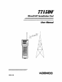
INSTALL MODE
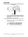
7720
OR
7820
7715DF
The 7715DF connects to the 772017820 via the supplied coiled cable, and places the 772017820 in
its test mode, i.e., Sets up the 772017820 to transmit 60 test messages. The node (master station)
evaluates the 772W7820 test message and dovmlinks the repeat count and signal strength it
received to the ~15DF,
NOTE:
THE ANTENNA MUST BE CONNECTED TO THE RADIO.
The INSTALLmodecan betetinated atmytime bypressingthe~
key, following
whichthe displayrevertsto “IIiSTAL”.
4
When the 7715DF is in any of its operational modes, the battery
voltage ischecked evetyl.5
minutes, If the battery voltage is
less than 6 volts the 7715DF ie automatically powered down,
-30-
-NOTES-
ADEMCO LIMITED WARRANTY
Alarm Device Manufacturing Company, a Division of Pittway Corporation,and its divisions, subsidiaries and affiliates (’<Seller”),
165 Eileen Way, Syosset, New York 11791,warrantsits products to be in conformancewith its own plans and specificationsand to
be fre8 from defects in materialsand workmanshipunder normal use and semice for 24 months from the date stamp control on the
product or, for producls not having an Ademco date stamp, for 12 months fmm date or original purchase unless the ins[alkdion
instructions or catalog sets fonh a shorter period, in which case the short period shall apply. Seller’s obligationshall be limited to
repairing or replacing,at its option, free of charge for materials or labor, any product which is proved not in compliancewith Seller’s
specificationsor proves defectivein materials or workmanshipunder normal use and service. Seller shall have no obligation under
this Limited Warrantyor otherwiseif the product is altered or improperlyrepairedor SerViCed by anyone other than Ademco factory
service, For warrantysemice, return product transportationprepaid, to AdemcoFactoryService, 165Eileen Way, Syosset,NewYork
11791,
THERE ARE NO WARRANTIES, EXPRESS OR IMPLIED, OF MERCHANTABILITY, OR FITNESS FOR A PARTICULAR
PURPOSEOR OTHERWISE,WHICHEXTENDBEYONDTHE DESCRIPTIONON THEFACEHEREOF. fN NO CASE SHALL
SELLERBE LfABLETO ANYONEFOR ANY CONSEQUENTIALOR INCIDENTALDAMAGESFOR BREACHOF THIS OR
ANY OTHERWARRANTY,EXPRESSOR IMPLIED,OR UPON ANYOTHERBASISOF LfABILfTYWHATSOEVER,EVEN
F THE LOSSOR DAMAGEIS CAUSEDBY THE SELLER’SOWNNEGLIGENCEOR FAULT.
Seller does not represent that [he products it sells may not be compromisedor circumvented; that the products will prevent any
personalinjury or propemyloss by burglary,robbery,tire or otherwise;or that the productswill in all cases provide adequatewarning
or protection. Customer understandsthat a properlyinstalled and maintainedalarm may only reduce tbe risk of a burglary,robbery,
fire or other events occurring withoutproviding an alarm, but it is not insuranceor a guarantee that such will not occur or that there
will he no personal injury or property loss as a result. CONSEQUENTLY, SELLER SHALL HAVE NO LfABILITY FOR ANY
PERSONALfNJURY, PROPERTYDAMAGE OR OTHER LOSS BASED ON A CLAIM THE PRODUCTFAlLED TO GIVE
WARNLNG. HOWEVER,tF SELLER JS HELD LIABLE,WHETHER DIRECTLYOR fNDIRECTLY,FOR ANY LOSS OR
DAMAGE ARISING UNDER THIS LIMITED WARRANTY OR OTHERWISE, REGARDLESSOF CAUSE OR ORIGIN,
SELLER’S MAXIMUM LIABJLJTYSHALL NOT IN ANY CASE EXCEED THE PURCHASEPRICE OF THEPRODUCT,
WHICH SHALLBE THE COMPLETE AND EXCLUSfVEREMEDY AGAINSTSELLER. This warranty replaces any previous
warrantiesand is the only warranty made by Seller on rftk product. No increaseor alteration, writtenor verbaf,of the obligationsof
this LimitedWarrantyis authorized.
ADEMCO
GROUP
165
Eileen Way, Syosset, New York 11791
Copyright C)1998 PITiWAY
N8B06
2/98
CORPORATION